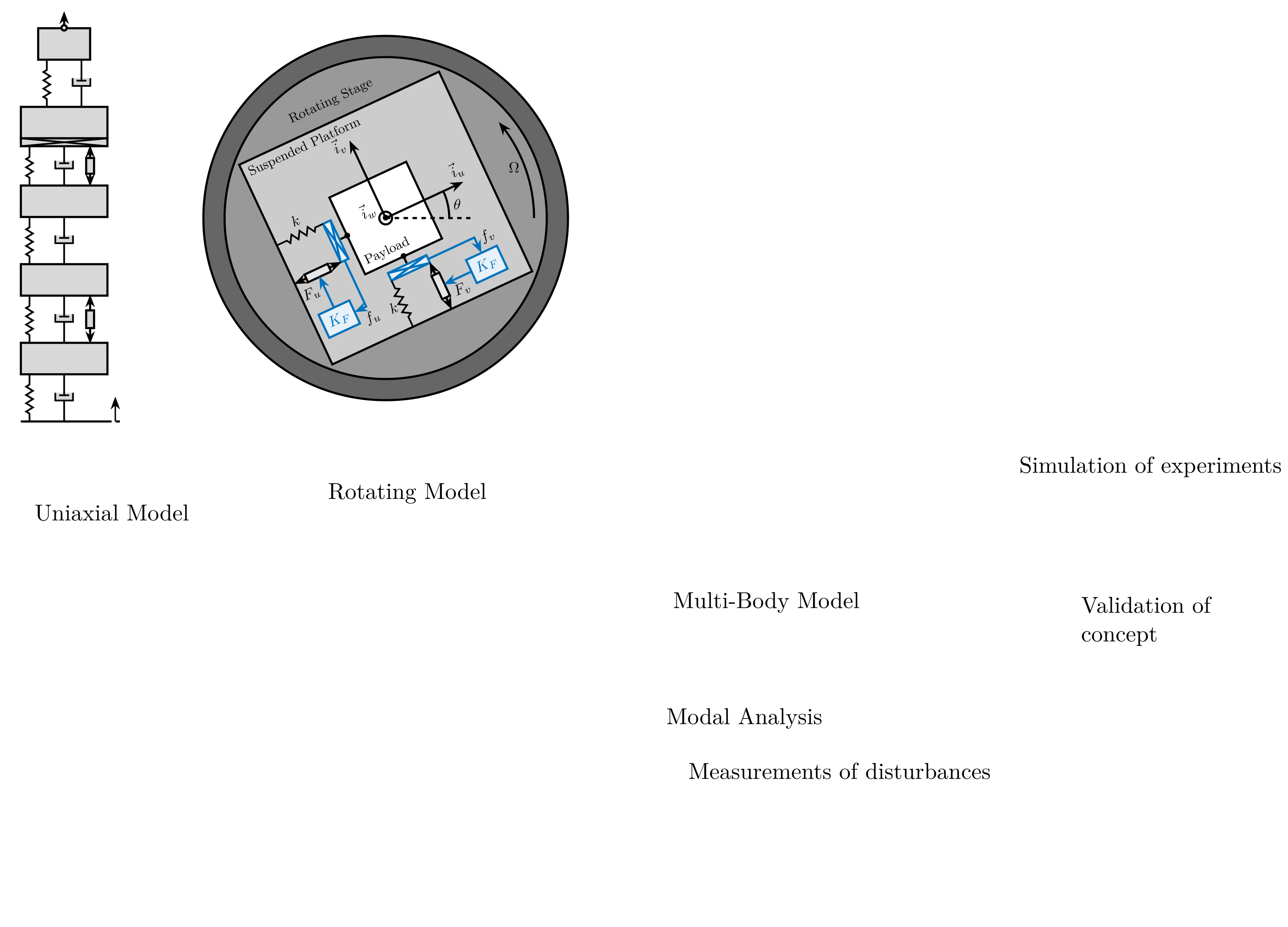
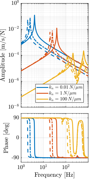
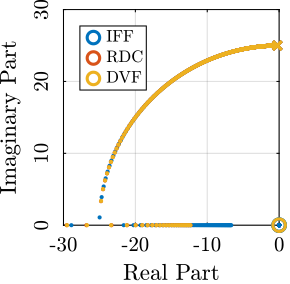
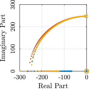
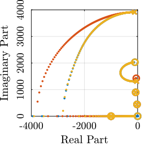
908 KiB
Glossary and Acronyms - Tables
| label | name | description |
|---|---|---|
| ms | \ensuremath{m_s} | Mass of the sample |
| mn | \ensuremath{m_n} | Mass of the nano-hexapod |
| mh | \ensuremath{m_h} | Mass of the micro-hexapod |
| mt | \ensuremath{m_t} | Mass of the micro-station stages |
| mg | \ensuremath{m_g} | Mass of the granite |
| xf | \ensuremath{x_f} | Floor motion |
| ft | \ensuremath{f_t} | Disturbance force of the micro-station |
| fs | \ensuremath{f_s} | Direct forces applied on the sample |
| d | \ensuremath{d} | Measured motion between the nano-hexapod and the granite |
| fn | \ensuremath{f_n} | Force sensor on the nano-hexapod |
| psdx | \ensuremath{Φx} | Power spectral density of signal $x$ |
| asdx | \ensuremath{Γx} | Amplitude spectral density of signal $x$ |
| cpsx | \ensuremath{Φx} | Cumulative Power Spectrum of signal $x$ |
| casx | \ensuremath{Γx} | Cumulative Amplitude Spectrum of signal $x$ |
| key | abbreviation | full form |
|---|---|---|
| haclac | HAC-LAC | High Authority Control - Low Authority Control |
| hac | HAC | High Authority Control |
| lac | LAC | Low Authority Control |
| nass | NASS | Nano Active Stabilization System |
| asd | ASD | Amplitude Spectral Density |
| psd | PSD | Power Spectral Density |
| cps | CPS | Cumulative Power Spectrum |
| cas | CAS | Cumulative Amplitude Spectrum |
| frf | FRF | Frequency Response Function |
| iff | IFF | Integral Force Feedback |
| rdc | RDC | Relative Damping Control |
| drga | DRGA | Dynamical Relative Gain Array |
| rga | RGA | Relative Gain Array |
| hpf | HPF | high-pass filter |
| lpf | LPF | low-pass filter |
| dof | DoF | Degree of freedom |
| svd | SVD | Singular Value Decomposition |
| mif | MIF | Mode Indicator Functions |
| dac | DAC | Digital to Analog Converter |
| fem | FEM | Finite Element Model |
| apa | APA | Amplified Piezoelectric Actuator |
Title Page
Abstract
Résumé
Acknowledgments
Table of Contents
Introduction
<<chap:introduction>>
Conceptual Design Development
<<chap:concept>> minitoc
Uni-axial Model
<<sec:uniaxial>>
Introduction
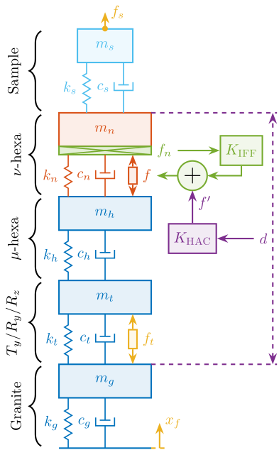
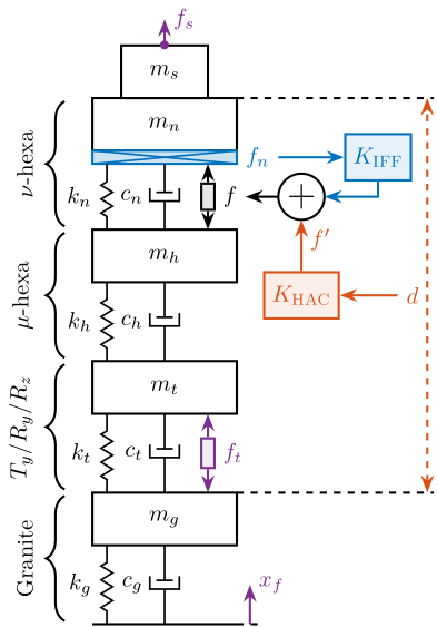
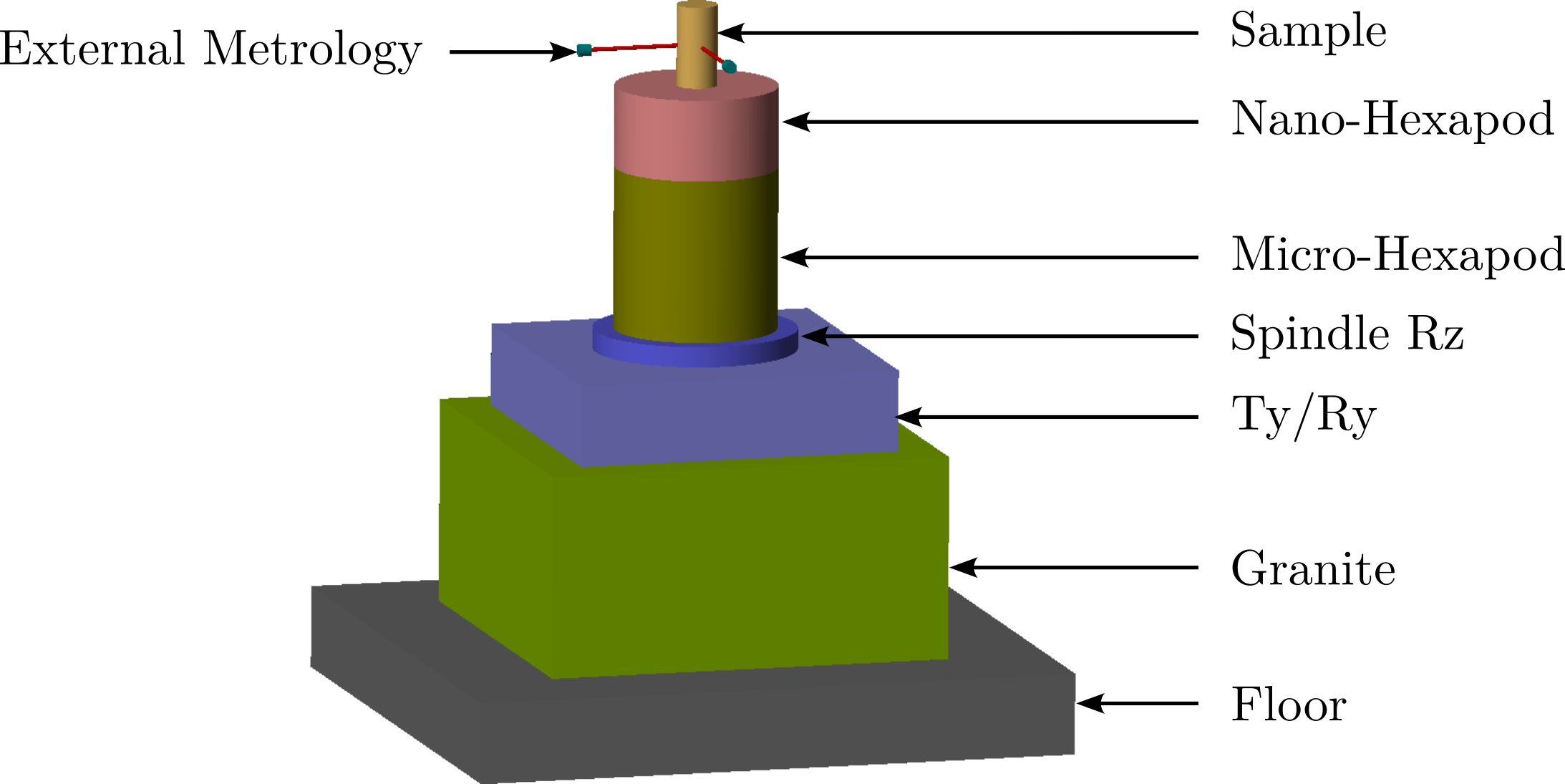
In this report, a uniaxial model of the acrfull:nass is developed and used to obtain a first idea of the challenges involved in this complex system. Note that in this study, only the vertical direction is considered (which is the most stiff), but other directions were considered as well, yielding to similar conclusions. The model is schematically shown in Figure ref:fig:uniaxial_overview_model_sections where the colors represent the parts studied in different sections.
To have a relevant model, the micro-station dynamics is first identified and its model is tuned to match the measurements (Section ref:sec:uniaxial_micro_station_model). Then, a model of the nano-hexapod is added on top of the micro-station. With the added sample and sensors, this gives a uniaxial dynamical model of the acrshort:nass that will be used for further analysis (Section ref:sec:uniaxial_nano_station_model).
The disturbances affecting position stability are identified experimentally (Section ref:sec:uniaxial_disturbances) and included in the model for dynamical noise budgeting (Section ref:sec:uniaxial_noise_budgeting). In all the following analysis, three nano-hexapod stiffnesses are considered to better understand the trade-offs and to find the most adequate nano-hexapod design. Three sample masses are also considered to verify the robustness of the applied control strategies with respect to a change of sample.
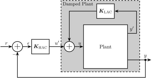
To improve the position stability of the sample, an acrfull:haclac strategy is applied. It consists of first actively damping the plant (the acrshort:lac part), and then applying a position control on the damped plant (the acrshort:hac part).
Three active damping techniques are studied (Section ref:sec:uniaxial_active_damping) which are used to both reduce the effect of disturbances and make the system easier to control afterwards. Once the system is well damped, a feedback position controller is applied and the obtained performance is analyzed (Section ref:sec:uniaxial_position_control).
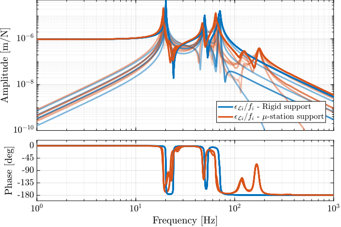
Two key effects that may limit that positioning performances are then considered: the limited micro-station compliance (Section ref:sec:uniaxial_support_compliance) and the presence of dynamics between the nano-hexapod and the sample's point of interest (Section ref:sec:uniaxial_payload_dynamics).
\begin{tikzpicture}
  % ====================
  % Parameters
  % ====================
  \def\massw{2.2}  % Width of the masses
  \def\massh{0.8}  % Height of the masses
  \def\spaceh{1.2} % Height of the springs/dampers
  \def\dispw{0.4}  % Width of the dashed line for the displacement
  \def\disph{0.3}  % Height of the arrow for the displacements
  \def\bracs{0.05} % Brace spacing vertically
  \def\brach{-12pt} % Brace shift horizontaly
  \def\fsensh{0.2} % Height of the force sensor
  \def\velsize{0.2} % Size of the velocity sensor
  % ====================

  % IFF
  % ====================
  % Ground
  % ====================
  \draw[draw=colorblue] (-0.5*\massw, 0) -- (0.5*\massw, 0);
  \draw[dashed,draw=coloryellow] (0.5*\massw, 0) -- ++(\dispw, 0);
  \draw[->, color=coloryellow] (0.5*\massw+0.5*\dispw, 0) -- ++(0, 2*\disph) node[right, color=coloryellow]{$x_{f}$};
  % ====================

  % ====================
  % Granite
  \begin{scope}[shift={(0, 0)}]
    % Mass
    \draw[draw=colorblue,fill=colorblue!10!white] (-0.5*\massw, \spaceh) rectangle (0.5*\massw, \spaceh+\massh) node[pos=0.5,color=colorblue]{$m_{g}$};

    % Spring, Damper, and Actuator
    \draw[spring,draw=colorblue]  (-0.4*\massw, 0) -- (-0.4*\massw, \spaceh) node[midway, left=0.1, color=colorblue]{$k_{g}$};
    \draw[damper={colorblue}{}{}] (0, 0)           -- ( 0, \spaceh)          node[midway, left=0.2, color=colorblue]{$c_{g}$};

    % Legend
    \draw[decorate, decoration={brace, amplitude=8pt}, xshift=\brach] %
    (-0.5*\massw, \bracs) -- (-0.5*\massw, \spaceh+\massh-\bracs) node[midway,rotate=90,anchor=south,yshift=10pt]{Granite};

    % Displacements
    \draw[dashed, draw=colorpurple] (0.5*\massw, \spaceh+\massh) -- ++(7.5*\dispw, 0) coordinate(xg);
  \end{scope}
  % ====================

  % ====================
  % Stages
  \begin{scope}[shift={(0, \spaceh+\massh)}]
    % Mass
    \draw[draw=colorblue,fill=colorblue!10!white] (-0.5*\massw, \spaceh) rectangle (0.5*\massw, \spaceh+\massh) node[pos=0.5,color=colorblue]{$m_{t}$};

    % Spring, Damper, and Actuator
    \draw[spring,draw=colorblue]  (-0.4*\massw, 0) -- (-0.4*\massw, \spaceh) node[midway, left=0.1,color=colorblue]{$k_{t}$};
    \draw[damper={colorblue}{}{}] (0, 0)           -- ( 0, \spaceh)          node[midway, left=0.2,color=colorblue]{$c_{t}$};

    % Disturbance
    \draw[actuator={0.45}{0.2}{coloryellow}] ( 0.3*\massw, 0) -- (0.3*\massw, \spaceh) node[midway, right=0.1, color=coloryellow](ft){$f_{t}$};

    % Legend
    \draw[decorate, decoration={brace, amplitude=8pt}, xshift=\brach] %
    (-0.5*\massw, \bracs) -- (-0.5*\massw, \spaceh+\massh-\bracs) node[midway,rotate=90,anchor=south,yshift=10pt]{$T_y$/$R_y$/$R_z$};
  \end{scope}
  % ====================

  % ====================
  % Hexapod
  \begin{scope}[shift={(0, 2*(\spaceh+\massh))}]
    % Mass
    \draw[draw=colorblue,fill=colorblue!10!white] (-0.5*\massw, \spaceh) rectangle (0.5*\massw, \spaceh+\massh) node[pos=0.5,color=colorblue]{$m_h$};

    % Spring, Damper, and Actuator
    \draw[spring,draw=colorblue]  (-0.4*\massw, 0) -- (-0.4*\massw, \spaceh) node[midway, left=0.1,color=colorblue]{$k_h$};
    \draw[damper={colorblue}{}{}] (0, 0)           -- ( 0, \spaceh)          node[midway, left=0.2,color=colorblue]{$c_h$};

    % Legend
    \draw[decorate, decoration={brace, amplitude=8pt}, xshift=\brach] %
    (-0.5*\massw, \bracs) -- (-0.5*\massw, \spaceh+\massh-\bracs) node[midway,rotate=90,anchor=south,yshift=10pt]{$\mu\text{-hexa}$};
  \end{scope}
  % ====================

  % ====================
  % NASS
  \begin{scope}[shift={(0, 3*(\spaceh+\massh))}]
    % Mass
    \draw[draw=colorred,fill=colorred!10!white] (-0.5*\massw, \spaceh) rectangle (0.5*\massw, \spaceh+\massh) node[pos=0.5,color=colorred]{$m_{n}$};

    % Force Sensor
    \node[forcesensor={\massw}{\fsensh}{colorgreen}] (fsensn) at (0, \spaceh-\fsensh){};
    \node[right, color=colorgreen] (fn) at (fsensn.east) {$f_n$};

    % Spring, Damper, and Actuator
    \draw[spring,draw=colorred]  (-0.4*\massw, 0) -- (-0.4*\massw, \spaceh-\fsensh) node[midway, left=0.1,color=colorred]{$k_{n}$};
    \draw[damper={colorred}{}{}] (0, 0)           -- ( 0, \spaceh-\fsensh)          node[midway, left=0.2,color=colorred]{$c_{n}$};
    \draw[actuator={0.4}{0.2}{colorred}] ( 0.3*\massw, 0) -- (0.3*\massw, \spaceh-\fsensh) node[midway, right=0.1,color=colorred](f){$f$};

    % Legend
    \draw[decorate, decoration={brace, amplitude=8pt}, xshift=\brach] %
    (-0.5*\massw, \bracs) -- (-0.5*\massw, \spaceh+\massh-\bracs) node[midway,rotate=90,anchor=south,yshift=10pt]{$\nu\text{-hexa}$};

    % Displacements
    \draw[dashed,draw=colorpurple] (0.5*\massw, \spaceh+\massh) -- ++(7.5*\dispw, 0) coordinate(xnpos);
  \end{scope}
  % ====================

  % ====================
  % sample
  \begin{scope}[shift={(0, 4*(\spaceh+\massh))}]
    % Mass
    \draw[draw=colorcyan,fill=colorcyan!10!white] (-0.3*\massw, \spaceh) rectangle (0.3*\massw, \spaceh+\massh) node[pos=0.5, color=colorcyan]{$m_{s}$};

    % Spring, Damper, and Actuator
    \draw[spring,draw=colorcyan] (-0.2*\massw, 0) -- (-0.2*\massw, \spaceh) node[midway, left=0.1, color=colorcyan]{$k_{s}$};
    \draw[damper={colorcyan}{}{}] ( 0.2*\massw, 0) -- ( 0.2*\massw, \spaceh) node[midway, left=0.2, color=colorcyan]{$c_{s}$};

    % Legend
    \draw[decorate, decoration={brace, amplitude=8pt}, xshift=\brach] %
    (-0.5*\massw, \bracs) -- (-0.5*\massw, \spaceh+\massh-\bracs) %
    node[midway,rotate=90,anchor=south,yshift=10pt,align=center]{Sample};

    % External Force
    \draw[->, color=coloryellow] (0, \spaceh+\massh) node[]{$\bullet$} -- ++(0, 0.5*\massh) node[right, color=coloryellow]{$f_s$};
  \end{scope}
  % ====================

  % Measured displacement
  \draw[<->, dashed, draw=colorpurple] ($(xg)+(-0.1, 0)$) -- node[left, color=colorpurple](d){$d$} ($(xnpos)+(-0.1, 0)$);

  % ====================
  % IFF Control
  \node[block={2em}{2em}, right=1.0 of fn, color=colorgreen, fill=colorgreen!10!white] (iff) {$K_{\textsc{IFF}}$};
  \node[addb, draw=colorgreen, fill=colorgreen!10!white, right=0.5 of f.east] (ctrladd) {};
  \node[block={2em}{2em}, color=colorpurple, fill=colorpurple!10!white] (Khac) at (ctrladd|-d) {$K_{\textsc{HAC}}$};

  \draw[->, draw=colorgreen] (fn.east) -- (iff.west);
  \draw[->, draw=colorgreen] (iff.south) |- (ctrladd.east);
  \draw[->, draw=colorgreen] (ctrladd.west) -- (f.east);

  \draw[->, draw=colorpurple] (d.west) -- (Khac.east);
  \draw[->, draw=colorpurple] (Khac.north) -- (ctrladd.south) node[below right, color=colorpurple]{$f^{\prime}$};
  % ====================
\end{tikzpicture}Micro Station Model
<<sec:uniaxial_micro_station_model>>
Introduction
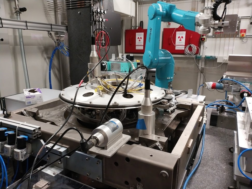
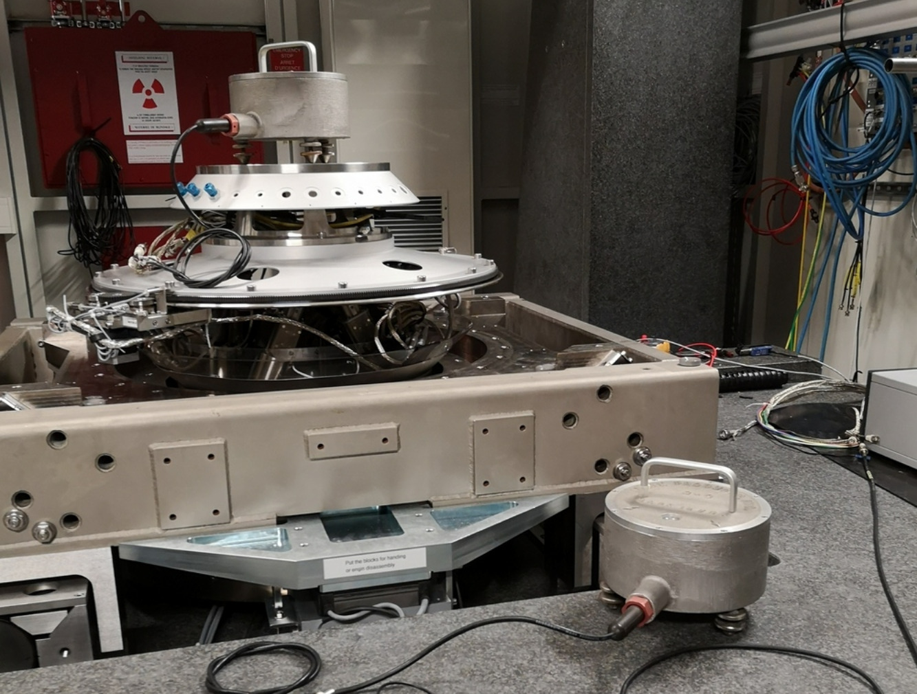
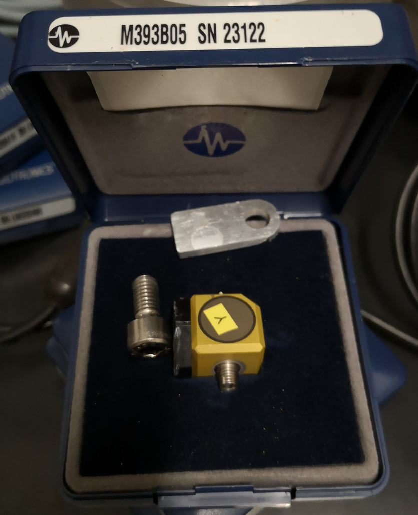
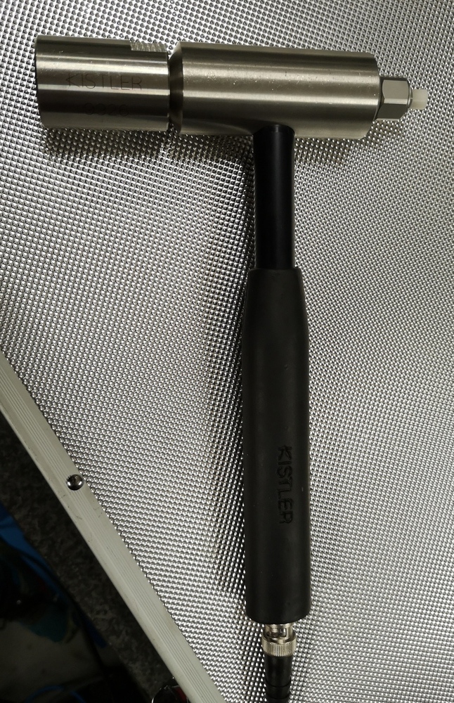
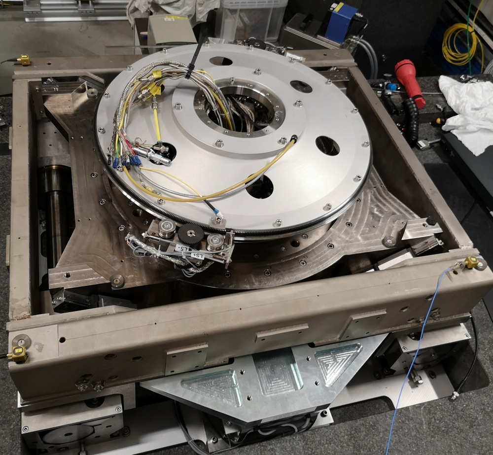
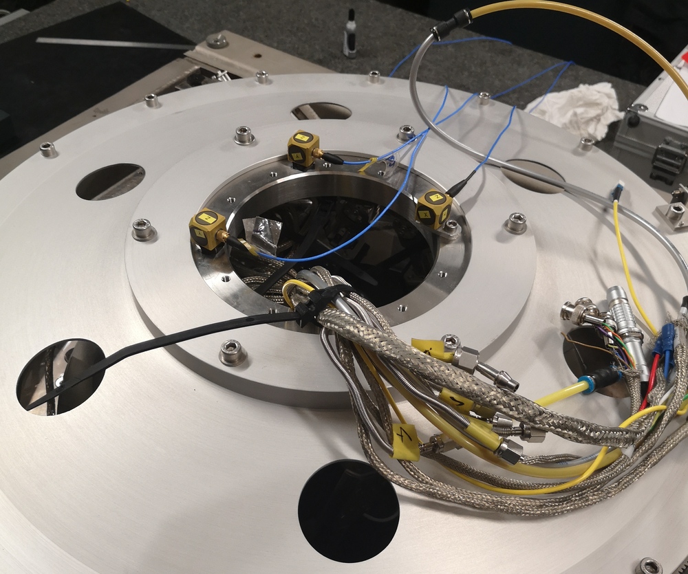
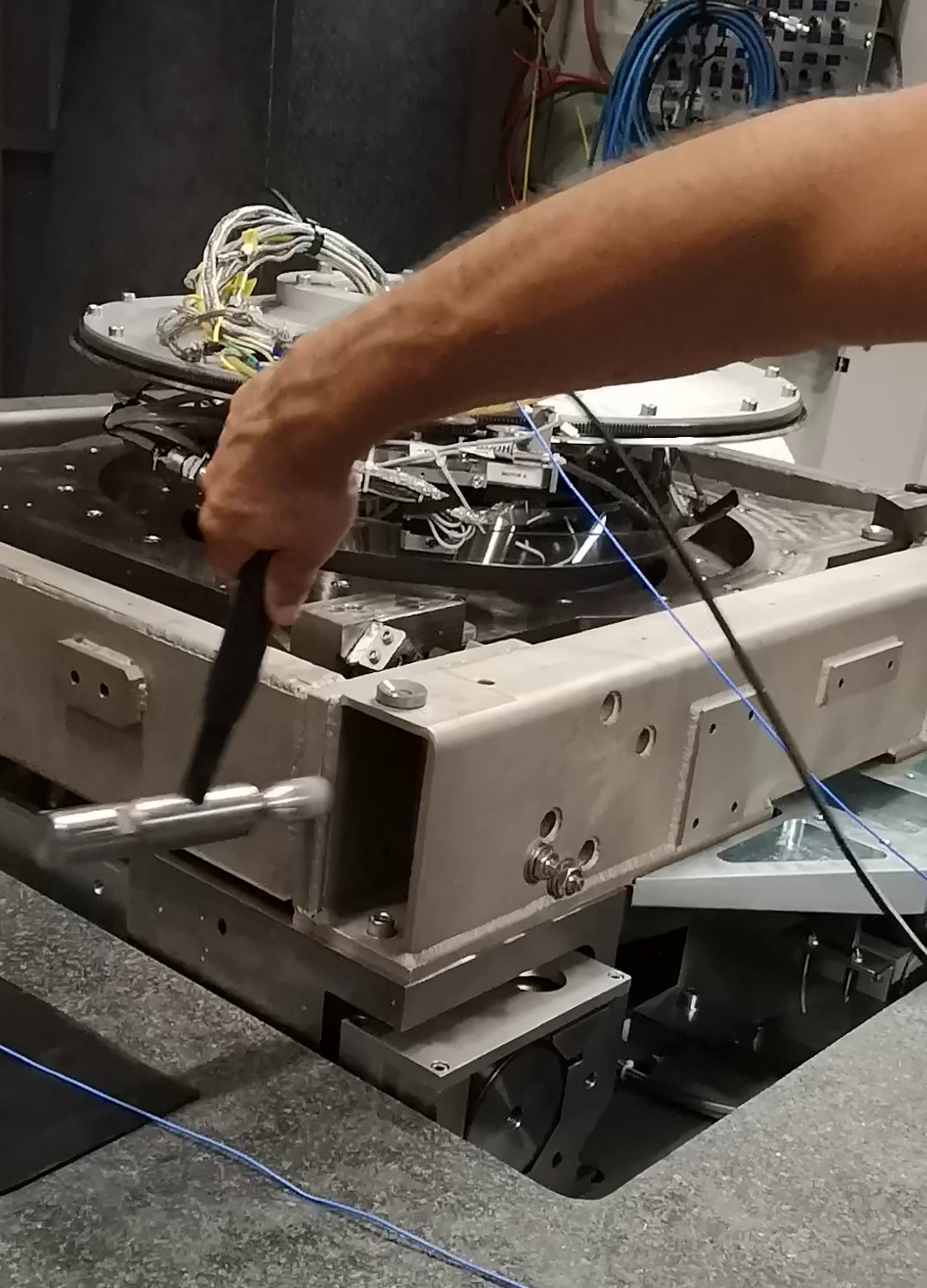
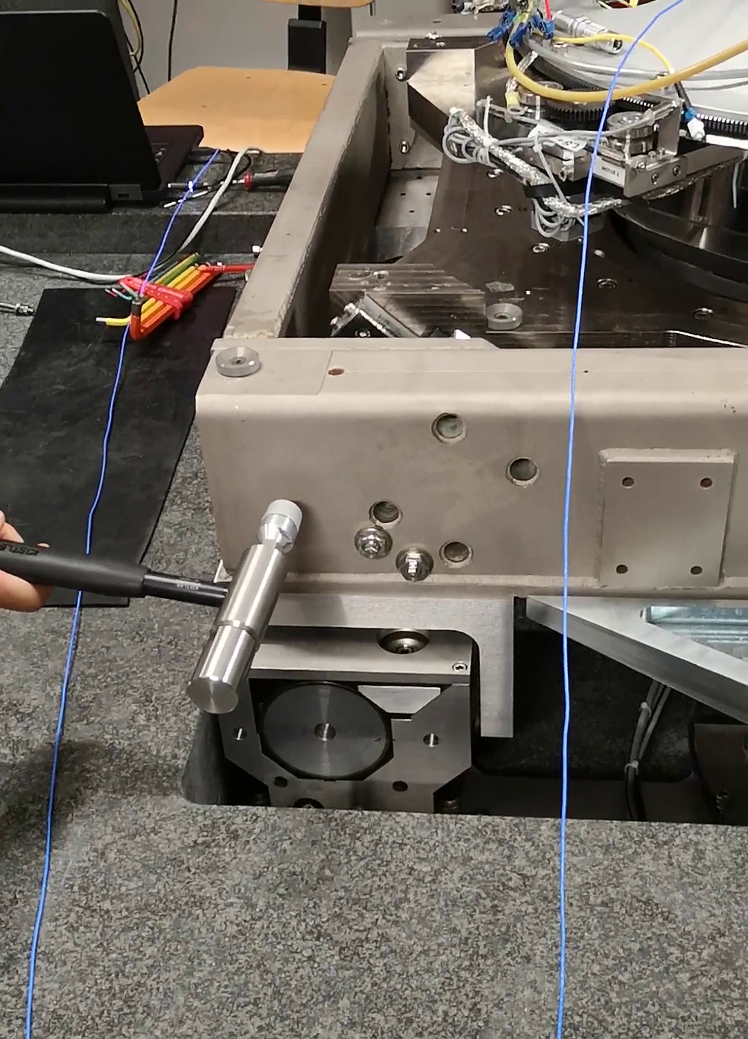
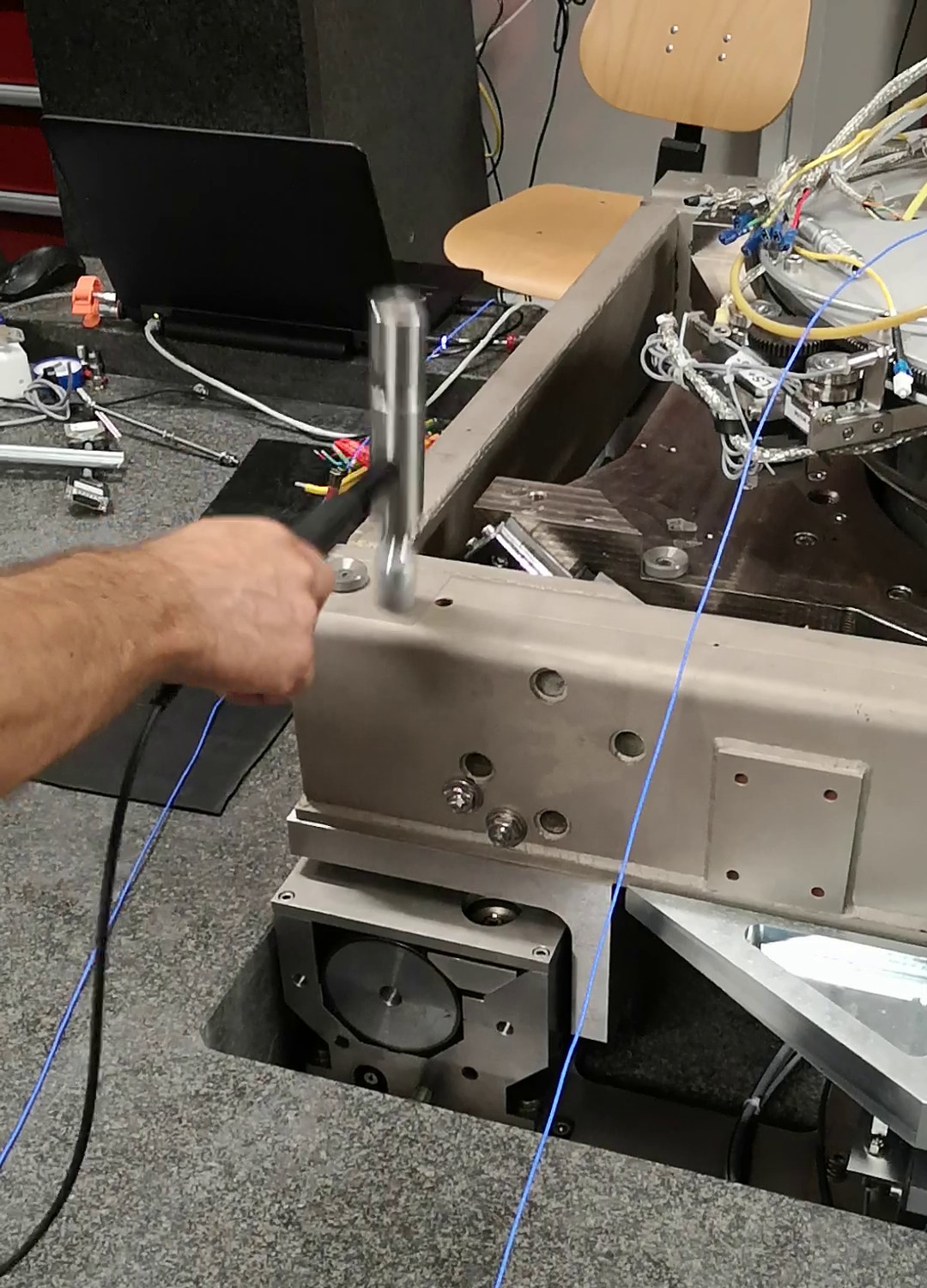
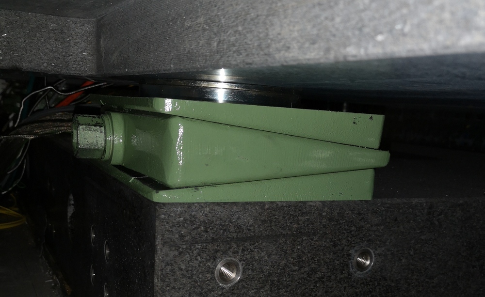
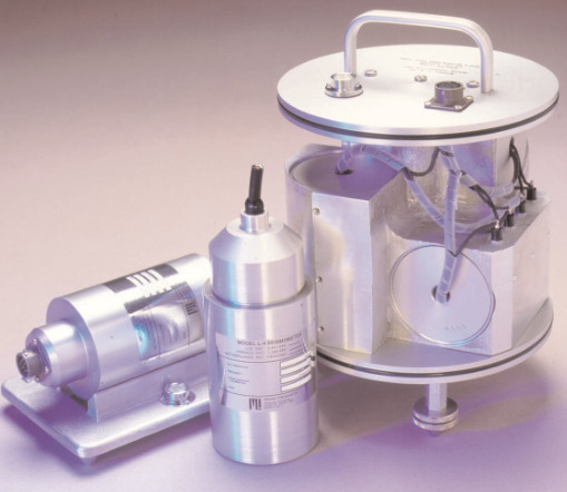
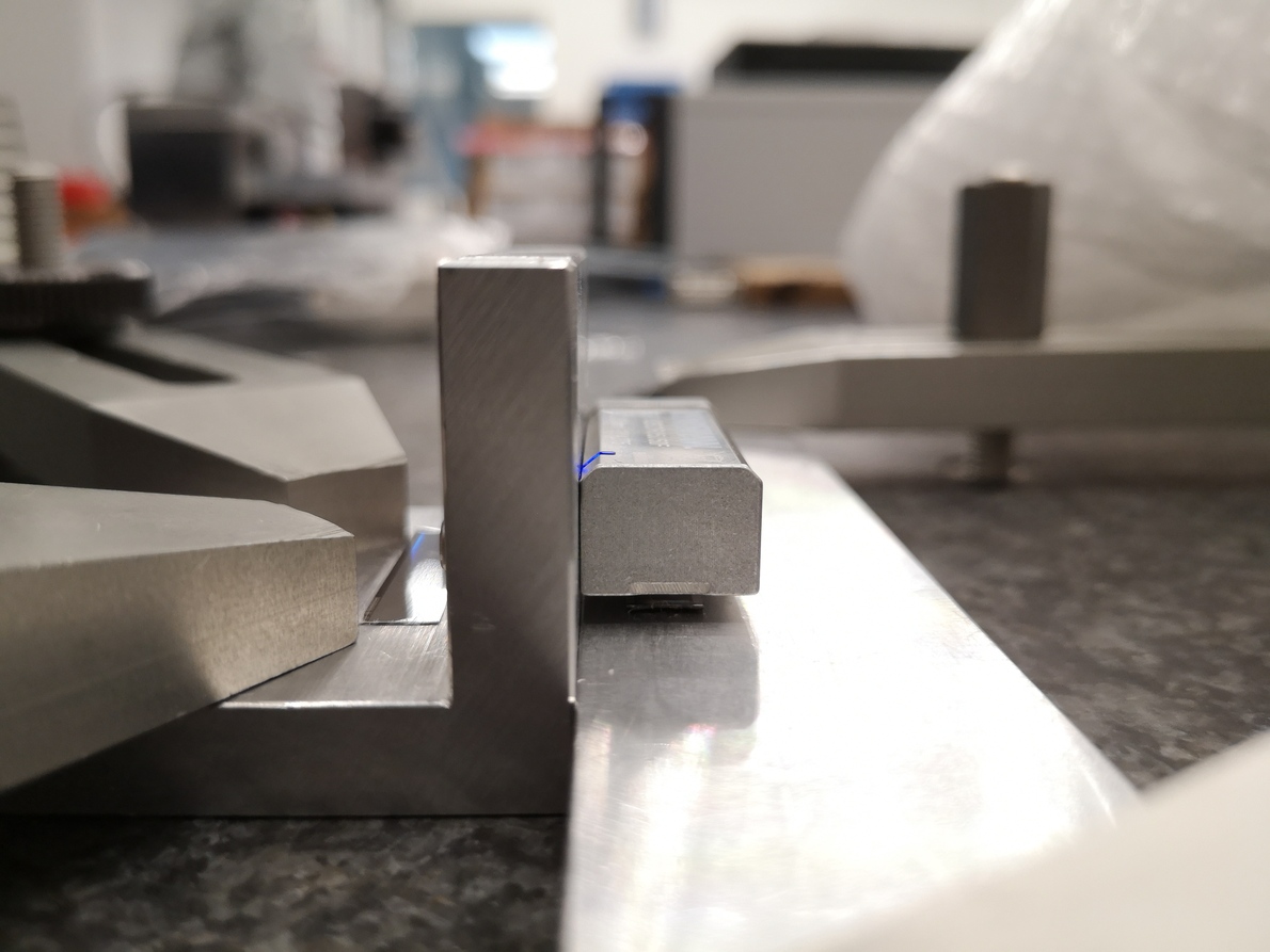
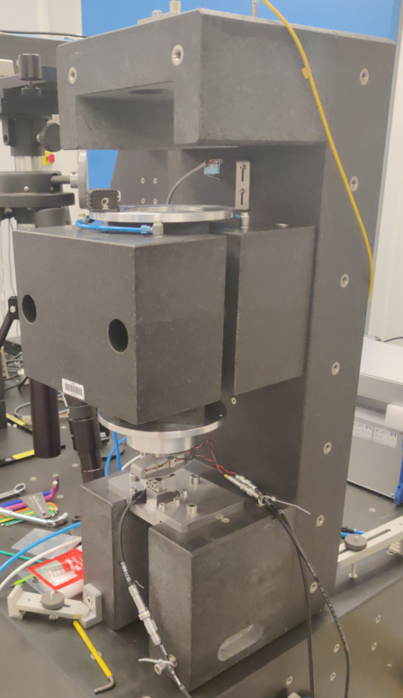
In this section, a uniaxial model of the micro-station is tuned to match measurements made on the micro-station. The measurement setup is shown in Figure ref:fig:uniaxial_ustation_first_meas_dynamics where several geophones1 are fixed to the micro-station and an instrumented hammer is used to inject forces on different stages of the micro-station.
From the measured frequency response functions (FRF), the model can be tuned to approximate the uniaxial dynamics of the micro-station.
Measured dynamics
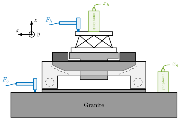
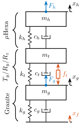
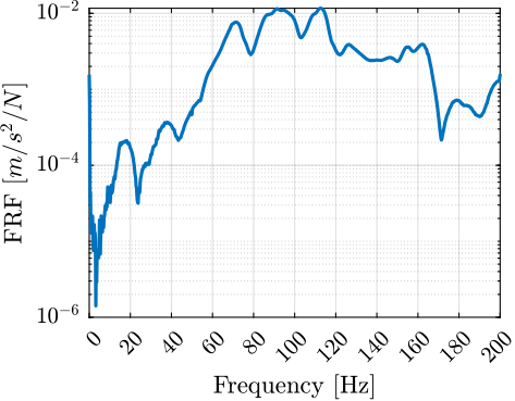
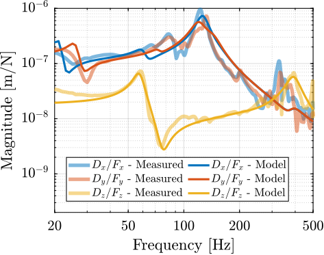
The measurement setup is schematically shown in Figure ref:fig:uniaxial_ustation_meas_dynamics_schematic where two vertical hammer hits are performed, one on the Granite (force $F_{g}$) and the other on the micro-hexapod's top platform (force $F_{h}$). The vertical inertial motion of the granite $x_{g}$ and the top platform of the micro-hexapod $x_{h}$ are measured using geophones. Three frequency response functions were computed: one from $F_{h}$ to $x_{h}$ (i.e., the compliance of the micro-station), one from $F_{g}$ to $x_{h}$ (or from $F_{h}$ to $x_{g}$) and one from $F_{g}$ to $x_{g}$.
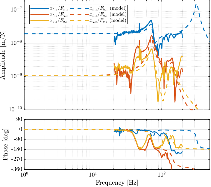
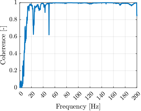
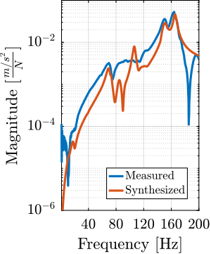
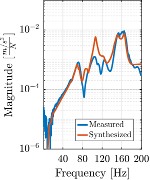
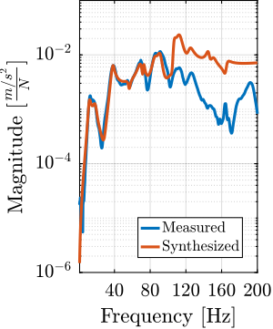
Due to the poor coherence at low frequencies, these frequency response functions will only be shown between 20 and 200Hz (solid lines in Figure ref:fig:uniaxial_comp_frf_meas_model).
\begin{tikzpicture}
  % Parameters
  \def\blockw{6.0cm}
  \def\blockh{1.2cm}

  \def\tiltdeg{0}
  \coordinate[] (rotationpoint) at (0, 4.5*\blockh);

  \begin{scope}[rotate around={\tiltdeg:(rotationpoint)}]
    % Tilt
    \path[] ([shift=(-120:4*\blockh)]rotationpoint) coordinate(beginarc) arc (-120:-110:4*\blockh) %
    -- ([shift=(-70:4*\blockh)]rotationpoint) arc (-70:-60:4*\blockh)%
    |- ++(-0.15*\blockw, 0.6*\blockh) coordinate (spindlene)%
    |- ($(beginarc) + (0.15*\blockw, 0.2*\blockh)$) coordinate (spindlesw) -- ++(0, 0.4*\blockh) coordinate(tiltte) -| cycle;

    % Spindle
    \coordinate[] (spindlese) at (spindlesw-|spindlene);
    \draw[fill=black!30] ($(spindlese)+(-0.1,0.1)+(-0.1*\blockw, 0)$) -| ($(spindlene)+(-0.1, 0)$) -| coordinate[pos=0.25](spindletop) ($(spindlesw)+(0.1,0.1)$) -| ++(0.1*\blockw, -\blockh) -| coordinate[pos=0.25](spindlebot) cycle;

    % \draw[dashed, color=black!60] ($(spindletop)+(0, 0.2)$) -- ($(spindlebot)+(0,-0.2)$);

    % Tilt
    \draw[fill=black!60] ([shift=(-120:4*\blockh)]rotationpoint) coordinate(beginarc) arc (-120:-110:4*\blockh) %
    -- ([shift=(-70:4*\blockh)]rotationpoint) arc (-70:-60:4*\blockh)%
    |- coordinate (tiltne) ++(-0.15*\blockw, 0.6*\blockh) coordinate (spindlene)%
    |- ($(beginarc) + (0.15*\blockw, 0.2*\blockh)$) coordinate (spindlesw) -- ++(0, 0.4*\blockh) -| cycle;

    % Micro-Hexapod
    \begin{scope}[shift={(spindletop)}]
      % Parameters definitions
      \def\baseh{0.22*\blockh} % Height of the base
      \def\naceh{0.18*\blockh} % Height of the nacelle
      \def\baser{0.22*\blockw} % Radius of the base
      \def\nacer{0.18*\blockw} % Radius of the nacelle

      \def\armr{0.2*\blockh} % Radius of the arms
      \def\basearmborder{0.2}
      \def\nacearmborder{0.2}

      \def\xnace{0} \def\ynace{\blockh-\naceh} \def\anace{0}
      \def\xbase{0} \def\ybase{0} \def\abase{0}

      % Hexapod1
      \begin{scope}[shift={(\xbase, \ybase)}, rotate=\abase]
        % Base
        \draw[fill=white] (-\baser, 0) coordinate[](uhexabot) rectangle (\baser, \baseh);

        \coordinate[] (armbasel) at (-\baser+\basearmborder+\armr, \baseh);
        \coordinate[] (armbasec) at (0, \baseh);
        \coordinate[] (armbaser) at (\baser-\basearmborder-\armr, \baseh);

        \begin{scope}[shift={(\xnace, \ynace)}, rotate=\anace]
          \draw[fill=white] (-\nacer, 0) rectangle (\nacer, \naceh);
          \coordinate[] (uhexatop) at (0, \naceh);
          \coordinate[] (armnacel) at (-\nacer+\nacearmborder+\armr, 0);
          \coordinate[] (armnacec) at (0, 0);
          \coordinate[] (armnacer) at (\nacer-\nacearmborder-\armr, 0);
        \end{scope}

        \draw[] (armbasec) -- (armnacer);
        \draw[] (armbasec) -- (armnacel);
        \draw[] (armbasel) -- coordinate(mhexaw) (armnacel);
        \draw[] (armbasel) -- (armnacec);
        \draw[] (armbaser) -- (armnacec);
        \draw[] (armbaser) -- coordinate(mhexae) (armnacer);
      \end{scope}
    \end{scope}

    \begin{scope}[shift={(uhexatop)}] % Geophone - Hexapod
      \draw[draw=colorgreen, fill=colorgreen!10!white] (-0.3, 0) rectangle node[midway, color=colorgreen, rotate=90]{\tiny geophone} (0.3, 1.2);
      \draw[rounded corners=0.1, draw=colorgreen, fill=colorgreen!10!white] (-0.1, 1.2) -- ++(0, 0.1) -- ++(0.1, 0.1) -- ++(0.1, -0.1) -- ++(0, -0.1) --cycle;
      \node[fill,shape=circle,minimum size=3pt,inner sep=0pt, color=colorgreen] at (0, 1.4){};
      \draw[out=90, in=180, draw=colorgreen] (0, 1.4) to ++(0.4, 0.2) node[right, color=colorgreen]{$x_{h}$};
    \end{scope}

    \begin{scope}[shift={(uhexatop)}] % Instrumented Hammer - Hexapod
      \begin{scope}[shift={(-1.5, 0)}]
        \draw[fill=white, rounded corners=0.2, draw=colorblue, fill=colorblue!10!white] (-0.5, 0.42) rectangle (0.5, 0.58);
        \draw[fill=white, rounded corners=0.2, draw=colorblue, fill=colorblue!10!white] (0.5, 0.15) rectangle (0.7, 0.8);
        \draw[fill=white, rounded corners=0.2, color=colorblue] (0.55, 0.15) rectangle (0.65, 0);
        \draw[out=180, in=0, draw=colorblue] (-0.5, 0.5) to ++(-0.6, -0.1) node[above, color=colorblue]{$F_{h}$};
        \node[fill,shape=circle,minimum size=3pt,inner sep=0pt, color=colorblue] at (-0.5, 0.5){};
      \end{scope}
    \end{scope}
  \end{scope}

  \begin{scope}[shift={(0, -0.3*\blockh)}]
    % Translation Stage - fixed part
    \draw[fill=black!40] (-0.5*\blockw, 0) coordinate[](tyb) rectangle (0.5*\blockw, 0.15*\blockh);
    \coordinate[] (measposbot) at (0.5*\blockw, 0);

    % Translation Stage - mobile part
    \draw[fill=black!10, fill opacity=0.5] (-0.5*\blockw, 0.2*\blockh) -- (-0.5*\blockw, 1.5*\blockh) coordinate[](tyt) -- (0.5*\blockw, 1.5*\blockh) -- (0.5*\blockw, 0.2*\blockh) -- (0.35*\blockw, 0.2*\blockh) -- (0.35*\blockw, 0.8*\blockh) -- (-0.35*\blockw, 0.8*\blockh) -- (-0.35*\blockw, 0.2*\blockh) -- cycle;

    % Translation Guidance
    \draw[dashed, color=black!60] ($(-0.5*\blockw, 0)+( 0.075*\blockw,0.5*\blockh)$) circle (0.2*\blockh);
    \draw[dashed, color=black!60] ($( 0.5*\blockw, 0)+(-0.075*\blockw,0.5*\blockh)$) circle (0.2*\blockh);

    % \draw[fill, color=black] ($( 0.5*\blockw, 0)+(-0.075*\blockw,0.5*\blockh)$) circle (0.04);
    % \node[draw, circle, inner sep=0pt, minimum size=0.3cm, label=above:$T_y$] at ($( 0.5*\blockw, 0)+(-0.075*\blockw,0.5*\blockh)$){};

    % Tilt Guidance
    \draw[dashed, color=black!60] ([shift=(-107:4.1*\blockh)]rotationpoint) arc (-107:-120:4.1*\blockh);
    \draw[dashed, color=black!60] ([shift=( -73:4.1*\blockh)]rotationpoint) arc (-73:-60:4.1*\blockh);

    \begin{scope}[shift={(4.0, 0)}] % Geophone - Granite
      \draw[draw=colorgreen, fill=colorgreen!10!white] (-0.3, 0) rectangle node[midway, color=colorgreen, rotate=90]{\tiny geophone} (0.3, 1.2);
      \draw[rounded corners=0.1, draw=colorgreen, fill=colorgreen!10!white] (-0.1, 1.2) -- ++(0, 0.1) -- ++(0.1, 0.1) -- ++(0.1, -0.1) -- ++(0, -0.1) --cycle;
      \node[fill,shape=circle,minimum size=3pt,inner sep=0pt, color=colorgreen] at (0, 1.4){};
      \draw[out=90, in=180, draw=colorgreen] (0, 1.4) to ++(0.4, 0.2) node[right, color=colorgreen]{$x_{g}$};
    \end{scope}

    \begin{scope}[shift={(-4.0, 0)}] % Instrumented Hammer - Granite
      \draw[fill=white, rounded corners=0.2, draw=colorblue, fill=colorblue!10!white] (-0.5, 0.42) rectangle (0.5, 0.58);
      \draw[fill=white, rounded corners=0.2, draw=colorblue, fill=colorblue!10!white] (0.5, 0.15) rectangle (0.7, 0.8);
      \draw[fill=white, rounded corners=0.2, color=colorblue] (0.55, 0.15) rectangle (0.65, 0);
      \draw[out=180, in=0, draw=colorblue] (-0.5, 0.5) to ++(-0.6, -0.1) node[above, color=colorblue]{$F_{g}$};
      \node[fill,shape=circle,minimum size=3pt,inner sep=0pt, color=colorblue] at (-0.5, 0.5){};
    \end{scope}
  \end{scope}

  % Granite
  \draw[fill=black!40] (-0.8*\blockw, -0.3*\blockh) rectangle node[midway]{Granite} (0.8*\blockw, -1.5*\blockh);

  % Vertical line
  % \draw[dashed, color=black] (spindlebot) -- ++(0, 2*\blockh);
  % \node[] at ($(spindlebot)+(0, 1.1*\blockh)$) {\AxisRotator[rotate=-90]};
  % \node[right, shift={(0.3,0)}] at ($(spindlebot)+(0, 1.1*\blockh)$) {$\theta_z$};

  % Axis
  \begin{scope}[shift={(-0.6*\blockw, 2.5*\blockh)}]
    \def\axissize{0.8cm}
    \draw[->] (0, 0) -- ++(0, \axissize) node[right]{$z$};
    \draw[->] (0, 0) -- ++(-\axissize, 0) node[above]{$x$};
    \draw[fill, color=black] (0, 0) circle (0.05*\axissize);
    \node[draw, circle, inner sep=0pt, minimum size=0.4*\axissize, label=right:$y$] (yaxis) at (0, 0){};
  \end{scope}
\end{tikzpicture}
Uniaxial Model
The uniaxial model of the micro-station is shown in Figure ref:fig:uniaxial_model_micro_station. It consists of a mass spring damper system with three degrees of freedom. A mass-spring-damper system represents the granite (with mass $m_g$, stiffness $k_g$ and damping $c_g$). Another mass-spring-damper system represents the different micro-station stages (the $T_y$ stage, the $R_y$ stage and the $R_z$ stage) with mass $m_t$, damping $c_t$ and stiffness $k_t$. Finally, a third mass-spring-damper system represents the micro-hexapod with mass $m_h$, damping $c_h$ and stiffness $k_h$.
The masses of the different stages are estimated from the 3D model, while the stiffnesses are from the data-sheet of the manufacturers. The damping coefficients were tuned to match the damping identified from the measurements. The parameters obtained are summarized in Table ref:tab:uniaxial_ustation_parameters.
| Stage | Mass | Stiffness | Damping |
|---|---|---|---|
| Micro-Hexapod | $m_h = 15\,\text{kg}$ | $k_h = 61\,N/\mu m$ | $c_h = 3\,\frac{kN}{m/s}$ |
| $T_y$, $R_y$, $R_z$ | $m_t = 1200\,\text{kg}$ | $k_t = 520\,N/\mu m$ | $c_t = 80\,\frac{kN}{m/s}$ |
| Granite | $m_g = 2500\,\text{kg}$ | $k_g = 950\,N/\mu m$ | $c_g = 250\,\frac{kN}{m/s}$ |
Two disturbances are considered which are shown in red: the floor motion $x_f$ and the stage vibrations represented by $f_t$. The hammer impacts $F_{h}, F_{g}$ are shown in blue, whereas the measured inertial motions $x_{h}, x_{g}$ are shown in black.
\begin{tikzpicture}
  % ====================
  % Parameters
  % ====================
  \def\massw{2.2}  % Width of the masses
  \def\massh{0.8}  % Height of the masses
  \def\spaceh{1.2} % Height of the springs/dampers
  \def\dispw{0.4}  % Width of the dashed line for the displacement
  \def\disph{0.4}  % Height of the arrow for the displacements
  \def\bracs{0.05} % Brace spacing vertically
  \def\brach{-12pt} % Brace shift horizontaly
  \def\fsensh{0.2} % Height of the force sensor
  \def\velsize{0.2} % Size of the velocity sensor
  % ====================

  % ====================
  % Floor
  % ====================
  \draw (-0.5*\massw, 0) -- (0.5*\massw, 0);
  \draw[dashed] (0.5*\massw, 0) -- ++(\dispw, 0);
  \draw[->, draw=colorred] (0.5*\massw+0.5*\dispw, 0) -- ++(0, \disph) node[right, color=colorred]{$x_{f}$};
  % ====================

  % ====================
  % Granite
  \begin{scope}[shift={(0, 0)}]
    % Mass
    \draw[fill=white] (-0.5*\massw, \spaceh) rectangle (0.5*\massw, \spaceh+\massh) node[pos=0.5]{$m_{g}$};

    % Spring, Damper, and Actuator
    \draw[spring] (-0.4*\massw, 0) -- (-0.4*\massw, \spaceh) node[midway, left=0.1]{$k_{g}$};
    \draw[damper] (0, 0)           -- ( 0, \spaceh)          node[midway, left=0.2]{$c_{g}$};

    % Legend
    \draw[decorate, decoration={brace, amplitude=8pt}, xshift=\brach] %
    (-0.5*\massw, \bracs) -- (-0.5*\massw, \spaceh+\massh-\bracs) node[midway,rotate=90,anchor=south,yshift=10pt]{Granite};

    % Displacement
    \draw[dashed] (0.5*\massw, \spaceh+\massh) -- ++(\dispw, 0);
    \draw[->] (0.5*\massw+0.5*\dispw, \spaceh+\massh) -- ++(0, \disph) node[right]{$x_{g}$};
  \end{scope}
  % ====================

  % ====================
  % Stages
  \begin{scope}[shift={(0, \spaceh+\massh)}]
    % Mass
    \draw[fill=white] (-0.5*\massw, \spaceh) rectangle (0.5*\massw, \spaceh+\massh) node[pos=0.5]{$m_{t}$};

    % Spring, Damper, and Actuator
    \draw[spring] (-0.4*\massw, 0) -- (-0.4*\massw, \spaceh) node[midway, left=0.1]{$k_{t}$};
    \draw[damper] (0, 0)           -- ( 0, \spaceh)          node[midway, left=0.2]{$c_{t}$};

    % Disturbance
    \draw[actuator={0.45}{0.2}{colorred}] ( 0.3*\massw, 0) -- (0.3*\massw, \spaceh) node[midway, right=0.1, color=colorred](ft){$f_t$};

    % Legend
    \draw[decorate, decoration={brace, amplitude=8pt}, xshift=\brach] %
    (-0.5*\massw, \bracs) -- (-0.5*\massw, \spaceh+\massh-\bracs) node[midway,rotate=90,anchor=south,yshift=10pt]{$T_y$/$R_y$/$R_z$};

    % External Force
    \draw[->, color=colorblue] (0, 0)node[branch] -- ++(0, 1.5*\dispw) node[below right]{$F_g$};

    % % Displacement
    % \draw[dashed] (0.5*\massw, \spaceh+\massh) -- ++(\dispw, 0);
    % \draw[->] (0.5*\massw+0.5*\dispw, \spaceh+\massh) -- ++(0, \disph) node[right]{$x_{t}$};
  \end{scope}
  % ====================

  % ====================
  % Hexapod
  \begin{scope}[shift={(0, 2*(\spaceh+\massh))}]
    % Mass
    \draw[fill=white] (-0.5*\massw, \spaceh) rectangle (0.5*\massw, \spaceh+\massh) node[pos=0.5]{$m_{h}$};

    % Spring, Damper, and Actuator
    \draw[spring] (-0.4*\massw, 0) -- (-0.4*\massw, \spaceh) node[midway, left=0.1]{$k_{h}$};
    \draw[damper] (0, 0)           -- ( 0, \spaceh)          node[midway, left=0.2]{$c_{h}$};

    % Legend
    \draw[decorate, decoration={brace, amplitude=8pt}, xshift=\brach] %
    (-0.5*\massw, \bracs) -- (-0.5*\massw, \spaceh+\massh-\bracs) node[midway,rotate=90,anchor=south,yshift=10pt]{$\mu\text{Hexa}$};

    % Displacement
    \draw[dashed] (0.5*\massw, \spaceh+\massh) -- ++(\dispw, 0);
    \draw[->] (0.5*\massw+0.5*\dispw, \spaceh+\massh) -- ++(0, \disph) node[right]{$x_{h}$};

    % External Force
    \draw[->, color=colorblue] (0, \spaceh+\massh)node[branch] -- ++(0, 1.5*\dispw) node[below right]{$F_h$};
  \end{scope}
  % ====================
\end{tikzpicture}
Comparison of model and measurements
The transfer functions from the forces injected by the hammers to the measured inertial motion of the micro-hexapod and granite are extracted from the uniaxial model and compared to the measurements in Figure ref:fig:uniaxial_comp_frf_meas_model.
Because the uniaxial model has three degrees of freedom, only three modes with frequencies at $70\,\text{Hz}$, $140\,\text{Hz}$ and $320\,\text{Hz}$ are modeled. Many more modes can be observed in the measurements (see Figure ref:fig:uniaxial_comp_frf_meas_model). However, the goal is not to have a perfect match with the measurement (this would require a much more complex model), but to have a first approximation. More accurate models will be used later on.
Nano-Hexapod Model
<<sec:uniaxial_nano_station_model>>
Introduction
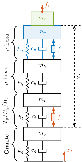
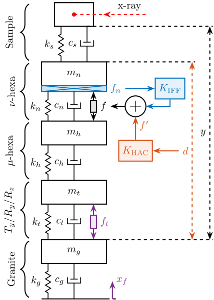
A model of the nano-hexapod and sample is now added on top of the uniaxial model of the micro-station (Figure ref:fig:uniaxial_model_micro_station_nass). Disturbances (shown in red) are gls:fs the direct forces applied to the sample (for example cable forces), gls:ft representing the vibrations induced when scanning the different stages and gls:xf the floor motion. The control signal is the force applied by the nano-hexapod $f$ and the measurement is the relative motion between the sample and the granite $d$. The sample is here considered as a rigid body and rigidly fixed to the nano-hexapod. The effect of resonances between the sample's point of interest and the nano-hexapod actuator will be considered in Section ref:sec:uniaxial_payload_dynamics.
\begin{tikzpicture}
  % ====================
  % Parameters
  % ====================
  \def\massw{2.2}  % Width of the masses
  \def\massh{0.8}  % Height of the masses
  \def\spaceh{1.2} % Height of the springs/dampers
  \def\dispw{0.4}  % Width of the dashed line for the displacement
  \def\disph{0.3}  % Height of the arrow for the displacements
  \def\bracs{0.05} % Brace spacing vertically
  \def\brach{-12pt} % Brace shift horizontaly
  \def\fsensh{0.2} % Height of the force sensor
  \def\velsize{0.2} % Size of the velocity sensor
  % ====================

  % ====================
  % Ground
  % ====================
  \draw (-0.5*\massw, 0) -- (0.5*\massw, 0);
  \draw[dashed] (0.5*\massw, 0) -- ++(\dispw, 0);
  \draw[->, color=colorred] (0.5*\massw+0.5*\dispw, 0) -- ++(0, 2*\disph) node[right, color=colorred]{$x_{f}$};
  % ====================

  % ====================
  % Marble
  \begin{scope}[shift={(0, 0)}]
    % Mass
    \draw[fill=white] (-0.5*\massw, \spaceh) rectangle (0.5*\massw, \spaceh+\massh) node[pos=0.5]{$m_{g}$};

    % Spring, Damper, and Actuator
    \draw[spring] (-0.4*\massw, 0) -- (-0.4*\massw, \spaceh) node[midway, left=0.1]{$k_{g}$};
    \draw[damper] (0, 0)           -- ( 0, \spaceh)          node[midway, left=0.2]{$c_{g}$};

    % Legend
    \draw[decorate, decoration={brace, amplitude=8pt}, xshift=\brach] %
    (-0.5*\massw, \bracs) -- (-0.5*\massw, \spaceh+\massh-\bracs) node[midway,rotate=90,anchor=south,yshift=10pt]{Granite};

    % Displacements
    \draw[dashed] (0.5*\massw, \spaceh+\massh) -- ++(2*\dispw, 0) coordinate(xm) -- ++(\dispw, 0) coordinate(dbot);
  \end{scope}
  % ====================

  % ====================
  % Stages
  \begin{scope}[shift={(0, \spaceh+\massh)}]
    % Mass
    \draw[fill=white] (-0.5*\massw, \spaceh) rectangle (0.5*\massw, \spaceh+\massh) node[pos=0.5]{$m_{t}$};

    % % Spring, Damper, and Actuator
    \draw[spring] (-0.4*\massw, 0) -- (-0.4*\massw, \spaceh) node[midway, left=0.1]{$k_{t}$};
    \draw[damper] (0, 0)           -- ( 0, \spaceh)          node[midway, left=0.2]{$c_{t}$};
    \draw[actuator={0.45}{0.2}{colorred}] ( 0.3*\massw, 0) -- (0.3*\massw, \spaceh) node[midway, right=0.1, color=colorred](ft){$f_{t}$};

    Legend
    \draw[decorate, decoration={brace, amplitude=8pt}, xshift=\brach] %
    (-0.5*\massw, \bracs) -- (-0.5*\massw, \spaceh+\massh-\bracs) node[midway,rotate=90,anchor=south,yshift=10pt]{$T_y$/$R_y$/$R_z$};
  \end{scope}
  % ====================

  % ====================
  % Hexapod
  \begin{scope}[shift={(0, 2*(\spaceh+\massh))}]
    % Mass
    \draw[fill=white] (-0.5*\massw, \spaceh) rectangle (0.5*\massw, \spaceh+\massh) node[pos=0.5]{$m_{h}$};

    % Spring, Damper, and Actuator
    \draw[spring] (-0.4*\massw, 0) -- (-0.4*\massw, \spaceh) node[midway, left=0.1]{$k_{h}$};
    \draw[damper] (0, 0)           -- ( 0, \spaceh)          node[midway, left=0.2]{$c_{h}$};

    % Legend
    \draw[decorate, decoration={brace, amplitude=8pt}, xshift=\brach] %
    (-0.5*\massw, \bracs) -- (-0.5*\massw, \spaceh+\massh-\bracs) node[midway,rotate=90,anchor=south,yshift=10pt]{$\mu\text{-hexa}$};
  \end{scope}
  % ====================

  % ====================
  % NASS
  \begin{scope}[shift={(0, 3*(\spaceh+\massh))}]
    % Mass
    \draw[fill=colorblue!10!white, draw=colorblue] (-0.5*\massw, \spaceh) rectangle (0.5*\massw, \spaceh+\massh) node[pos=0.5,color=colorblue]{$m_{n}$};

    % Spring, Damper, and Actuator
    \draw[spring, draw=colorblue] (-0.4*\massw, 0) -- (-0.4*\massw, \spaceh) node[midway, left=0.1, color=colorblue]{$k_{n}$};
    \draw[damper={colorblue}{}{}] (0, 0)           -- ( 0, \spaceh)          node[midway, left=0.2, color=colorblue]{$c_{n}$};
    \draw[actuator={0.4}{0.2}{colorblue}] ( 0.3*\massw, 0) -- (0.3*\massw, \spaceh) node[midway, right=0.1, color=colorblue](F){$f$};

    % Displacements
    \draw[dashed] (0.5*\massw, \spaceh+\massh) -- ++(2*\dispw, 0) coordinate(xn) -- ++(\dispw, 0) coordinate(drtop);

    % Legend
    \draw[decorate, decoration={brace, amplitude=8pt}, xshift=\brach] %
    (-0.5*\massw, \bracs) -- (-0.5*\massw, \spaceh+\massh-\bracs) node[midway,rotate=90,anchor=south,yshift=10pt]{$\nu\text{-hexa}$};
  \end{scope}
  % ====================

  % ====================
  % sample
  \begin{scope}[shift={(0, 4*(\spaceh+\massh))}]
    % Mass
    \draw[fill=colorgreen!10!white, draw=colorgreen] (-0.3*\massw, 0) rectangle (0.3*\massw, \massh) node[pos=0.5,color=colorgreen]{$m_{s}$};

    % External Force
    \draw[->, color=colorred] (0, \massh) node[]{$\bullet$} -- ++(0, 0.5*\massh) node[right, color=colorred]{$f_s$};
  \end{scope}
  % ====================

  % ====================
  % Measured Displacement
  \draw[<->, dashed] (xm) -- node[midway, right]{$d$} (xn);
  % ====================
\end{tikzpicture}
Nano-Hexapod Parameters
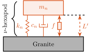
The nano-hexapod is represented by a mass spring damper system (shown in blue in Figure ref:fig:uniaxial_model_micro_station_nass). Its mass gls:mn is set to $15\,\text{kg}$ while its stiffness $k_n$ can vary depending on the chosen architecture/technology. The sample is represented by a mass gls:ms that can vary from $1\,\text{kg}$ up to $50\,\text{kg}$.
As a first example, the nano-hexapod stiffness of is set at $k_n = 10\,N/\mu m$ and the sample mass is chosen at $m_s = 10\,\text{kg}$.
Obtained Dynamic Response
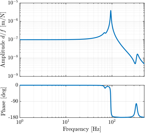
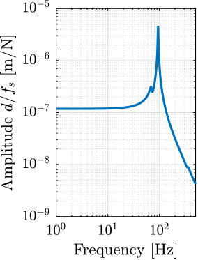
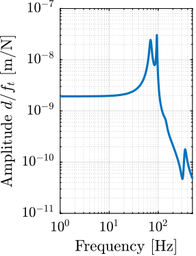
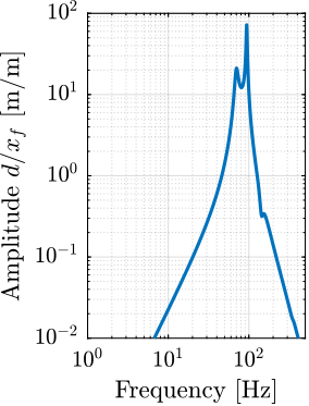
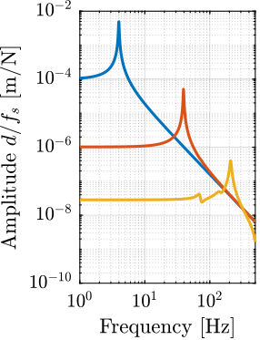
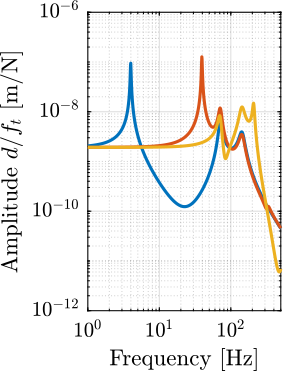
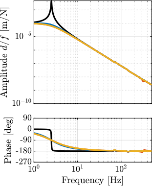
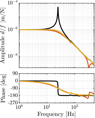
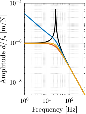
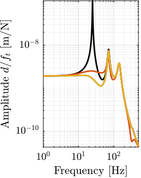
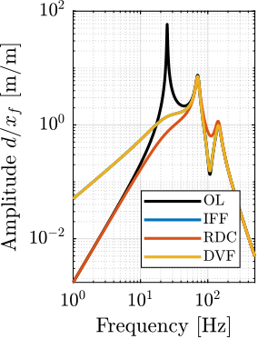
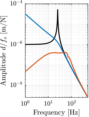
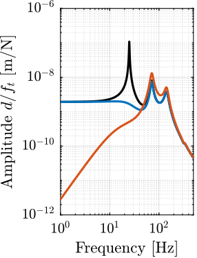
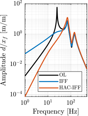
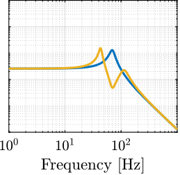
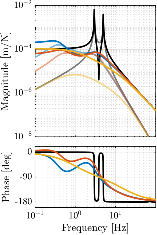
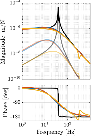
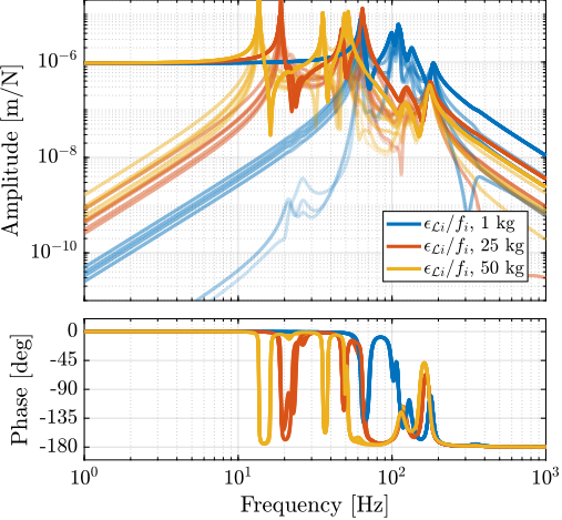
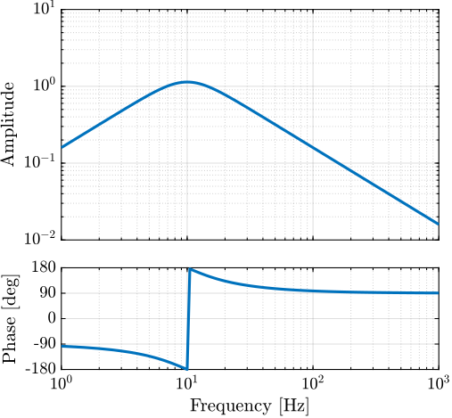
The sensitivity to disturbances (i.e., the transfer functions from $x_f,f_t,f_s$ to $d$) can be extracted from the uniaxial model of Figure ref:fig:uniaxial_model_micro_station_nass and are shown in Figure ref:fig:uniaxial_sensitivity_dist_first_params. The plant (i.e., the transfer function from actuator force $f$ to measured displacement $d$) is shown in Figure ref:fig:uniaxial_plant_first_params.
For further analysis, 9 "configurations" of the uniaxial NASS model of Figure ref:fig:uniaxial_model_micro_station_nass will be considered: three nano-hexapod stiffnesses ($k_n = 0.01\,N/\mu m$, $k_n = 1\,N/\mu m$ and $k_n = 100\,N/\mu m$) combined with three sample's masses ($m_s = 1\,kg$, $m_s = 25\,kg$ and $m_s = 50\,kg$).
Disturbance Identification
<<sec:uniaxial_disturbances>>
Introduction
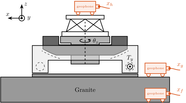
To quantify disturbances (red signals in Figure ref:fig:uniaxial_model_micro_station_nass), three geophones2 are used. One is located on the floor, another one on the granite, and the last one on the micro-hexapod's top platform (see Figure ref:fig:uniaxial_ustation_meas_disturbances). The geophone located on the floor was used to measure the floor motion $x_f$ while the other two geophones were used to measure vibrations introduced by scanning of the $T_y$ stage and $R_z$ stage (see Figure ref:fig:uniaxial_ustation_dynamical_id_setup).
\begin{tikzpicture}
  % Parameters
  \def\blockw{6.0cm}
  \def\blockh{1.2cm}

  \def\tiltdeg{0}
  \coordinate[] (rotationpoint) at (0, 4.5*\blockh);

  \begin{scope}[rotate around={\tiltdeg:(rotationpoint)}]
    % Tilt
    \path[] ([shift=(-120:4*\blockh)]rotationpoint) coordinate(beginarc) arc (-120:-110:4*\blockh) %
    -- ([shift=(-70:4*\blockh)]rotationpoint) arc (-70:-60:4*\blockh)%
    |- ++(-0.15*\blockw, 0.6*\blockh) coordinate (spindlene)%
    |- ($(beginarc) + (0.15*\blockw, 0.2*\blockh)$) coordinate (spindlesw) -- ++(0, 0.4*\blockh) coordinate(tiltte) -| cycle;

    % Spindle
    \coordinate[] (spindlese) at (spindlesw-|spindlene);
    \draw[fill=black!30] ($(spindlese)+(-0.1,0.1)+(-0.1*\blockw, 0)$) -| ($(spindlene)+(-0.1, 0)$) -| coordinate[pos=0.25](spindletop) ($(spindlesw)+(0.1,0.1)$) -| ++(0.1*\blockw, -\blockh) -| coordinate[pos=0.25](spindlebot) cycle;

    % \draw[dashed, color=black!60] ($(spindletop)+(0, 0.2)$) -- ($(spindlebot)+(0,-0.2)$);

    % Tilt
    \draw[fill=black!60] ([shift=(-120:4*\blockh)]rotationpoint) coordinate(beginarc) arc (-120:-110:4*\blockh) %
    -- ([shift=(-70:4*\blockh)]rotationpoint) arc (-70:-60:4*\blockh)%
    |- coordinate (tiltne) ++(-0.15*\blockw, 0.6*\blockh) coordinate (spindlene)%
    |- ($(beginarc) + (0.15*\blockw, 0.2*\blockh)$) coordinate (spindlesw) -- ++(0, 0.4*\blockh) -| cycle;

    % Micro-Hexapod
    \begin{scope}[shift={(spindletop)}]
      % Parameters definitions
      \def\baseh{0.22*\blockh} % Height of the base
      \def\naceh{0.18*\blockh} % Height of the nacelle
      \def\baser{0.22*\blockw} % Radius of the base
      \def\nacer{0.18*\blockw} % Radius of the nacelle

      \def\armr{0.2*\blockh} % Radius of the arms
      \def\basearmborder{0.2}
      \def\nacearmborder{0.2}

      \def\xnace{0} \def\ynace{\blockh-\naceh} \def\anace{0}
      \def\xbase{0} \def\ybase{0} \def\abase{0}

      % Hexapod
      \begin{scope}[shift={(\xbase, \ybase)}, rotate=\abase]
        % Base
        \draw[fill=white] (-\baser, 0) coordinate[](uhexabot) rectangle (\baser, \baseh);

        \coordinate[] (armbasel) at (-\baser+\basearmborder+\armr, \baseh);
        \coordinate[] (armbasec) at (0, \baseh);
        \coordinate[] (armbaser) at (\baser-\basearmborder-\armr, \baseh);

        \begin{scope}[shift={(\xnace, \ynace)}, rotate=\anace]
          \draw[fill=white] (-\nacer, 0) rectangle (\nacer, \naceh);
          \coordinate[] (uhexatop) at (0, \naceh);
          \coordinate[] (armnacel) at (-\nacer+\nacearmborder+\armr, 0);
          \coordinate[] (armnacec) at (0, 0);
          \coordinate[] (armnacer) at (\nacer-\nacearmborder-\armr, 0);
        \end{scope}

        \draw[] (armbasec) -- (armnacer);
        \draw[] (armbasec) -- (armnacel);
        \draw[] (armbasel) -- coordinate(mhexaw) (armnacel);
        \draw[] (armbasel) -- (armnacec);
        \draw[] (armbaser) -- (armnacec);
        \draw[] (armbaser) -- coordinate(mhexae) (armnacer);
      \end{scope}
    \end{scope}

    \begin{scope}[shift={(uhexatop)}] % Geophone - Hexapod
      \draw[rounded corners=0.1, draw=colorred, fill=colorred!10!white] (-0.5, 0.2) -- ++(0, -0.1) -- ++(0.1, -0.1) -- ++(0.1, 0.1) -- ++(0, 0.1) --cycle;
      \draw[rounded corners=0.1, draw=colorred, fill=colorred!10!white] ( 0.3, 0.2) -- ++(0, -0.1) -- ++(0.1, -0.1) -- ++(0.1, 0.1) -- ++(0, 0.1) --cycle;
      \draw[draw=colorred, fill=colorred!10!white] (0.6, 0.4) rectangle ++(0.2, 0.2);
      \node[shape=circle,minimum size=3pt,inner sep=0pt, draw=colorred, fill=colorred] at (0.8, 0.5){};
      \draw[out=0, in=180, draw=colorred] (0.8, 0.5) to ++(0.6, -0.1) node[above, color=colorred]{$x_h$};
      \draw[draw=colorred, fill=colorred!10!white] (-0.6, 0.2) rectangle node[midway, color=colorred]{\tiny geophone} (0.6, 0.8);
    \end{scope}
  \end{scope}

  \begin{scope}[shift={(0, -0.3*\blockh)}]
    % Translation Stage - fixed part
    \draw[fill=black!40] (-0.5*\blockw, 0) coordinate[](tyb) rectangle (0.5*\blockw, 0.15*\blockh);
    \coordinate[] (measposbot) at (0.5*\blockw, 0);

    % Translation Stage - mobile part
    \draw[fill=black!10, fill opacity=0.5] (-0.5*\blockw, 0.2*\blockh) -- (-0.5*\blockw, 1.5*\blockh) coordinate[](tyt) -- (0.5*\blockw, 1.5*\blockh) -- (0.5*\blockw, 0.2*\blockh) -- (0.35*\blockw, 0.2*\blockh) -- (0.35*\blockw, 0.8*\blockh) -- (-0.35*\blockw, 0.8*\blockh) -- (-0.35*\blockw, 0.2*\blockh) -- cycle;

    % Translation Guidance
    \draw[dashed, color=black!60] ($(-0.5*\blockw, 0)+( 0.075*\blockw,0.5*\blockh)$) circle (0.2*\blockh);
    \draw[dashed, color=black!60] ($( 0.5*\blockw, 0)+(-0.075*\blockw,0.5*\blockh)$) circle (0.2*\blockh);

    \draw[fill, color=black] ($( 0.5*\blockw, 0)+(-0.075*\blockw,0.5*\blockh)$) circle (0.04);
    \node[draw, circle, inner sep=0pt, minimum size=0.3cm, label=above:$T_y$] at ($( 0.5*\blockw, 0)+(-0.075*\blockw,0.5*\blockh)$){};

    % Tilt Guidance
    \draw[dashed, color=black!60] ([shift=(-107:4.1*\blockh)]rotationpoint) arc (-107:-120:4.1*\blockh);
    \draw[dashed, color=black!60] ([shift=( -73:4.1*\blockh)]rotationpoint) arc (-73:-60:4.1*\blockh);

    \begin{scope}[shift={(4.0, 0)}] % Geophone - Granite
      \draw[rounded corners=0.1, draw=colorred, fill=colorred!10!white] (-0.5, 0.2) -- ++(0, -0.1) -- ++(0.1, -0.1) -- ++(0.1, 0.1) -- ++(0, 0.1) --cycle;
      \draw[rounded corners=0.1, draw=colorred, fill=colorred!10!white] ( 0.3, 0.2) -- ++(0, -0.1) -- ++(0.1, -0.1) -- ++(0.1, 0.1) -- ++(0, 0.1) --cycle;
      \draw[draw=colorred, fill=colorred!10!white] (0.6, 0.4) rectangle ++(0.2, 0.2);
      \node[shape=circle,minimum size=3pt,inner sep=0pt, draw=colorred, fill=colorred] at (0.8, 0.5){};
      \draw[out=0, in=180, draw=colorred] (0.8, 0.5) to ++(0.6, -0.1) node[above, color=colorred]{$x_g$};
      \draw[draw=colorred, fill=colorred!10!white] (-0.6, 0.2) rectangle node[midway, color=colorred]{\tiny geophone} (0.6, 0.8);
    \end{scope}
  \end{scope}

  % Granite
  \draw[fill=black!40] (-0.8*\blockw, -0.3*\blockh) rectangle node[midway]{Granite} (0.8*\blockw, -1.5*\blockh);

  \begin{scope}[shift={(4.0, -1.5*\blockh)}] % Geophone - Floor
    \draw[rounded corners=0.1, draw=colorred, fill=colorred!10!white] (-0.5, 0.2) -- ++(0, -0.1) -- ++(0.1, -0.1) -- ++(0.1, 0.1) -- ++(0, 0.1) --cycle;
    \draw[rounded corners=0.1, draw=colorred, fill=colorred!10!white] ( 0.3, 0.2) -- ++(0, -0.1) -- ++(0.1, -0.1) -- ++(0.1, 0.1) -- ++(0, 0.1) --cycle;
    \draw[draw=colorred, fill=colorred!10!white] (0.6, 0.4) rectangle ++(0.2, 0.2);
    \node[shape=circle,minimum size=3pt,inner sep=0pt, draw=colorred, fill=colorred] at (0.8, 0.5){};
    \draw[out=0, in=180, draw=colorred] (0.8, 0.5) to ++(0.6, -0.1) node[above, color=colorred]{$x_f$};
    \draw[draw=colorred, fill=colorred!10!white] (-0.6, 0.2) rectangle node[midway, color=colorred]{\tiny geophone} (0.6, 0.8);
  \end{scope}

  % Vertical line
  \draw[dashed, color=black] (spindlebot) -- ++(0, 2*\blockh);
  \node[] at ($(spindlebot)+(0, 1.1*\blockh)$) {\AxisRotator[rotate=-90]};
  \node[right, shift={(0.3,0)}] at ($(spindlebot)+(0, 1.1*\blockh)$) {$\theta_z$};

  % Axis
  \begin{scope}[shift={(-0.6*\blockw, 2.5*\blockh)}]
    \def\axissize{0.8cm}
    \draw[->] (0, 0) -- ++(0, \axissize) node[right]{$z$};
    \draw[->] (0, 0) -- ++(-\axissize, 0) node[above]{$x$};
    \draw[fill, color=black] (0, 0) circle (0.05*\axissize);
    \node[draw, circle, inner sep=0pt, minimum size=0.4*\axissize, label=right:$y$] (yaxis) at (0, 0){};
  \end{scope}
\end{tikzpicture}
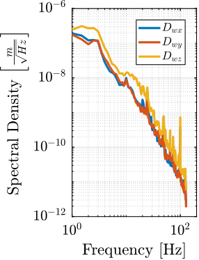
Ground Motion
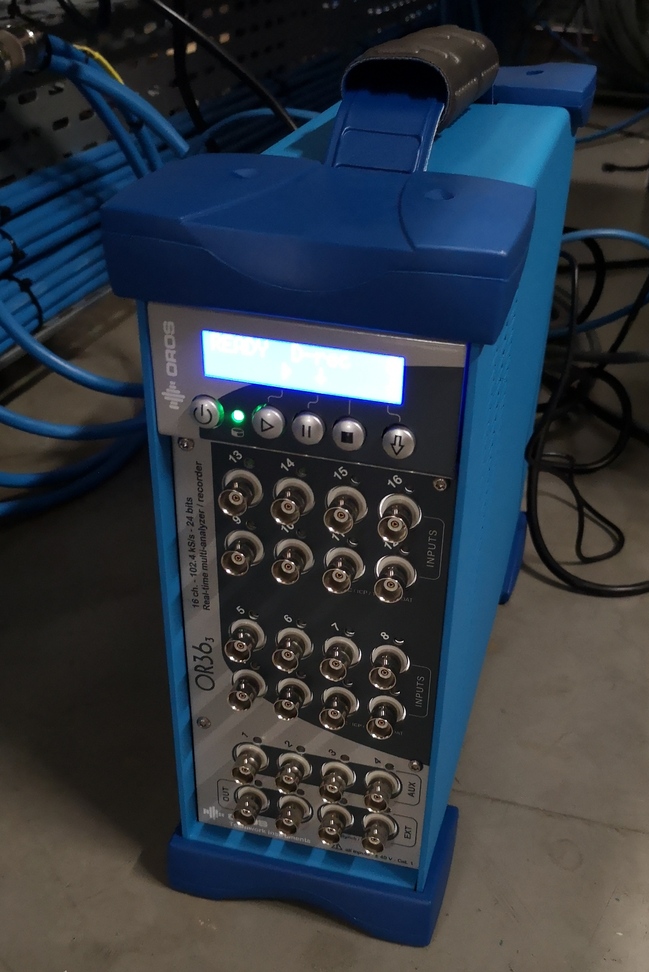
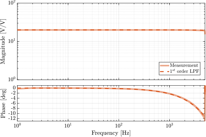
To acquire the geophone signals, the measurement setup shown in Figure ref:fig:uniaxial_geophone_meas_chain is used. The voltage generated by the geophone is amplified using a low noise voltage amplifier3 with a gain of 60dB before going to the ADC. This is done to improve the signal-to-noise ratio.
To reconstruct the displacement $x_f$ from the measured voltage $\hat{V}_{x_f}$, the transfer function of the measurement chain from $x_f$ to $\hat{V}_{x_f}$ needs to be estimated. First, the transfer function $G_{geo}$ from the floor motion $x_{f}$ to the generated geophone voltage $V_{x_f}$ is shown in eqref:eq:uniaxial_geophone_tf, with $T_g = 88\,\frac{V}{m/s}$ the sensitivity of the geophone, $f_0 = \frac{\omega_0}{2\pi} = 2\,\text{Hz}$ its resonance frequency and $\xi = 0.7$ its damping ratio. This model of the geophone was taken from cite:&collette12_review. The gain of the voltage amplifier is $V^{\prime}_{x_f}/V_{x_f} = g_0 = 1000$.
\begin{equation}\label{eq:uniaxial_geophone_tf} Ggeo(s) = \frac{Vx_f}{x_f}(s) = Tg ⋅ s ⋅ \frac{s^2}{s^2 + 2 ξ ω_0 s + ω_0^2} \quad ≤ft[ V/m \right]
\end{equation}
\begin{tikzpicture}
  \draw[rounded corners=0.1, draw=colorblack, fill=colorblack!10!white] (-0.5, 0.2) -- ++(0, -0.1) -- ++(0.1, -0.1) -- ++(0.1, 0.1) -- ++(0, 0.1) --cycle;
  \draw[rounded corners=0.1, draw=colorblack, fill=colorblack!10!white] ( 0.3, 0.2) -- ++(0, -0.1) -- ++(0.1, -0.1) -- ++(0.1, 0.1) -- ++(0, 0.1) --cycle;
  \draw[draw=colorblack, fill=colorblack!10!white] (0.6, 0.4) rectangle ++(0.2, 0.2);
  \node[shape=circle,minimum size=3pt,inner sep=0pt, draw=colorblack, fill=colorblack] at (0.8, 0.5){};
  \draw[out=0, in=180, draw=colorblack] (0.8, 0.5) to ++(0.6, -0.1) coordinate[](geophone_output);
  \draw[draw=colorblack, fill=colorblack!10!white] (-0.6, 0.2) rectangle node[midway, color=colorblack]{\tiny geophone} (0.6, 0.8);

  \draw[dashed] (-1, 0) -- (1, 0);
  \draw[->] (-0.8, 0) -- ++(0, 0.5)node[left]{$x_f$};
  \node[gain right, minimum width=0.8cm, right=0.5 of geophone_output] (gain) {$g_0$};
  \node[ADC, right=1 of gain] (adc) {ADC};
  \draw[->] (geophone_output) -- (gain.west) node[above left]{$V_{x_f}$};
  \draw[->] (gain.east) -- (adc.west) node[above left]{$V^{\prime}_{x_f}$};
  \draw[->] (adc.east) -- ++(1, 0) node[above left]{$\hat{V}_{x_f}$};
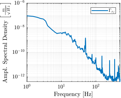
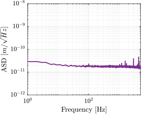
\end{tikzpicture}The amplitude spectral density of the floor motion $\Gamma_{x_f}$ can be computed from the amplitude spectral density of measured voltage $\Gamma_{\hat{V}_{x_f}}$ using eqref:eq:uniaxial_asd_floor_motion. The estimated amplitude spectral density $\Gamma_{x_f}$ of the floor motion $x_f$ is shown in Figure ref:fig:uniaxial_asd_floor_motion_id31.
\begin{equation}\label{eq:uniaxial_asd_floor_motion} Γx_f(ω) = \frac{Γ_{\hat{V}x_f}(ω)}{|Ggeo(jω)| ⋅ g_0} \quad ≤ft[ m/\sqrt{\text{Hz}} \right]
\end{equation}
Stage Vibration
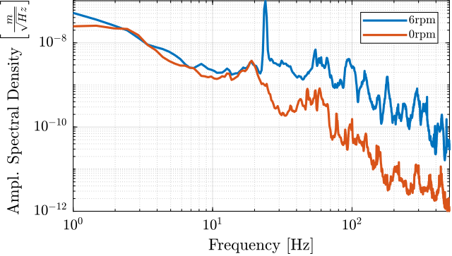
To estimate the vibrations induced by scanning the micro-station stages, two geophones are used, as shown in Figure ref:fig:uniaxial_ustation_dynamical_id_setup. The vertical relative velocity between the top platform of the micro hexapod and the granite is estimated in two cases: without moving the micro-station stages, and then during a Spindle rotation at 6rpm. The vibrations induced by the $T_y$ stage are not considered here because they have less amplitude than the vibrations induced by the $R_z$ stage and because the $T_y$ stage can be scanned at lower velocities if the induced vibrations are found to be an issue.
The amplitude spectral density of the relative motion with and without the Spindle rotation are compared in Figure ref:fig:uniaxial_asd_vibration_spindle_rotation. It is shown that the spindle rotation increases the vibrations above $20\,\text{Hz}$. The sharp peak observed at $24\,\text{Hz}$ is believed to be induced by electromagnetic interference between the currents in the spindle motor phases and the geophone cable because this peak is not observed when rotating the spindle "by hand".
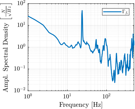
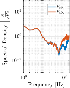
To compute the equivalent disturbance force $f_t$ (Figure ref:fig:uniaxial_model_micro_station) that induces such motion, the transfer function $G_{f_t}(s)$ from $f_t$ to the relative motion between the micro-hexapod's top platform and the granite $(x_{h} - x_{g})$ is extracted from the model. The amplitude spectral density $\Gamma_{f_{t}}$ of the disturbance force is them computed from eqref:eq:uniaxial_ft_asd and is shown in Figure ref:fig:uniaxial_asd_disturbance_force.
\begin{equation}\label{eq:uniaxial_ft_asd} Γ_{ft}(ω) = \frac{Γ_{Rz}(ω)}{|Gf_t(jω)|}
\end{equation}
Open-Loop Dynamic Noise Budgeting
<<sec:uniaxial_noise_budgeting>>
Introduction
Now that a model of the acrshort:nass has been obtained (see section ref:sec:uniaxial_nano_station_model) and that the disturbances have been estimated (see section ref:sec:uniaxial_disturbances), it is possible to perform an open-loop dynamic noise budgeting.
To perform such noise budgeting, the disturbances need to be modeled by their spectral densities (done in section ref:sec:uniaxial_disturbances). Then, the transfer functions from disturbances to the performance metric (here the distance $d$) are computed (Section ref:ssec:uniaxial_noise_budget_sensitivity). Finally, these two types of information are combined to estimate the corresponding spectral density of the performance metric. This is very useful to identify what is limiting the performance of the system, or the compare the achievable performance with different system parameters (Section ref:ssec:uniaxial_noise_budget_result).
Sensitivity to disturbances
<<ssec:uniaxial_noise_budget_sensitivity>> From the uniaxial model of the acrshort:nass (Figure ref:fig:uniaxial_model_micro_station_nass), the transfer function from the disturbances ($f_s$, $x_f$ and $f_t$) to the displacement $d$ are computed.
This is done for two extreme sample masses $m_s = 1\,\text{kg}$ and $m_s = 50\,\text{kg}$ and three nano-hexapod stiffnesses:
- $k_n = 0.01\,N/\mu m$ that represents a voice coil actuator with soft flexible guiding
- $k_n = 1\,N/\mu m$ that represents a voice coil actuator with a stiff flexible guiding or a mechanically amplified piezoelectric actuator
- $k_n = 100\,N/\mu m$ that represents a stiff piezoelectric stack actuator
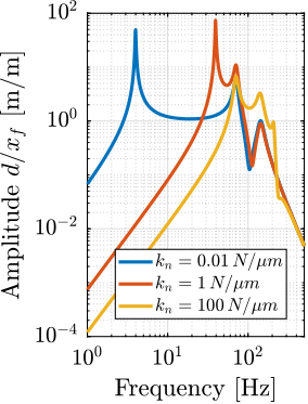
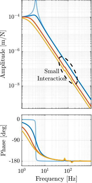
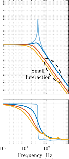
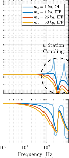
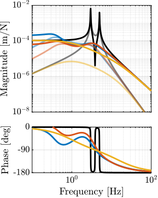
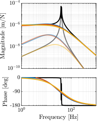
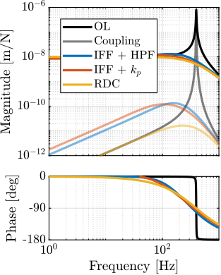
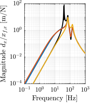
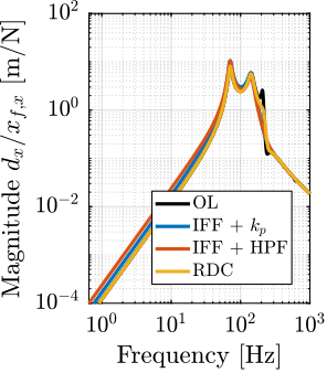
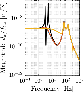
The obtained sensitivity to disturbances for the three nano-hexapod stiffnesses are shown in Figure ref:fig:uniaxial_sensitivity_disturbances_nano_hexapod_stiffnesses for the sample mass $m_s = 1\,\text{kg}$ (the same conclusions can be drawn with $m_s = 50\,\text{kg}$):
- The soft nano-hexapod is more sensitive to forces applied on the sample (cable forces for instance), which is expected due to its lower stiffness (Figure ref:fig:uniaxial_sensitivity_disturbances_nano_hexapod_stiffnesses_fs)
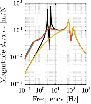
- Between the suspension mode of the nano-hexapod (here at 5Hz for the soft nano-hexapod) and the first mode of the micro-station (here at 70Hz), the disturbances induced by the stage vibrations are filtered out (Figure ref:fig:uniaxial_sensitivity_disturbances_nano_hexapod_stiffnesses_ft)
- Above the suspension mode of the nano-hexapod, the sample's inertial motion is unaffected by the floor motion; therefore, the sensitivity to floor motion is close to $1$ (Figure ref:fig:uniaxial_sensitivity_disturbances_nano_hexapod_stiffnesses_xf)
Open-Loop Dynamic Noise Budgeting
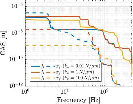
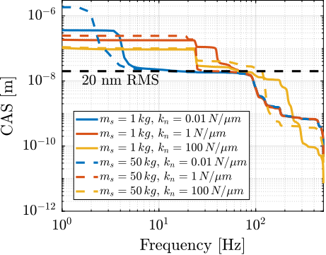
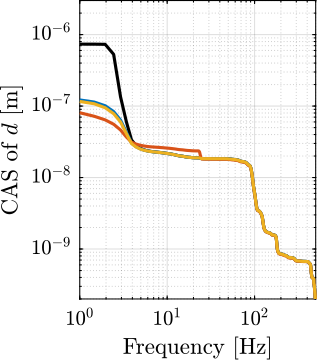
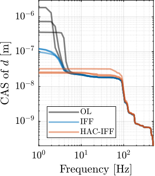
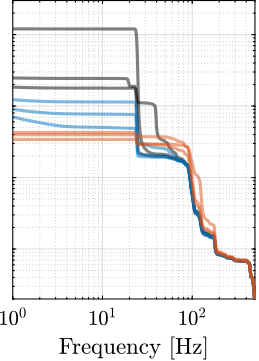
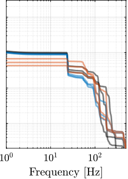
<<ssec:uniaxial_noise_budget_result>> Now, the amplitude spectral densities of the disturbances are considered to estimate the residual motion $d$ for each nano-hexapod and sample configuration. The Cumulative Amplitude Spectrum of the relative motion $d$ due to both floor motion $x_f$ and stage vibrations $f_t$ are shown in Figure ref:fig:uniaxial_cas_d_disturbances_stiffnesses for the three nano-hexapod stiffnesses. It is shown that the effect of floor motion is much less than that of stage vibrations, except for the soft nano-hexapod below $5\,\text{Hz}$.
The total cumulative amplitude spectrum of $d$ for the three nano-hexapod stiffnesses and for the two samples masses are shown in Figure ref:fig:uniaxial_cas_d_disturbances_payload_masses. The conclusion is that the sample mass has little effect on the cumulative amplitude spectrum of the relative motion $d$.
Conclusion
The open-loop residual vibrations of $d$ can be estimated from the low-frequency value of the cumulative amplitude spectrum in Figure ref:fig:uniaxial_cas_d_disturbances_payload_masses. This residual vibration of $d$ is found to be in the order of $100\,nm\,\text{RMS}$ for the stiff nano-hexapod ($k_n = 100\,N/\mu m$), $200\,nm\,\text{RMS}$ for the relatively stiff nano-hexapod ($k_n = 1\,N/\mu m$) and $1\,\mu m\,\text{RMS}$ for the soft nano-hexapod ($k_n = 0.01\,N/\mu m$). From this analysis, it may be concluded that the stiffer the nano-hexapod the better.
However, what is more important is the closed-loop residual vibration of $d$ (i.e., while the feedback controller is used). The goal is to obtain a closed-loop residual vibration $\epsilon_d \approx 20\,nm\,\text{RMS}$ (represented by an horizontal dashed black line in Figure ref:fig:uniaxial_cas_d_disturbances_payload_masses). The bandwidth of the feedback controller leading to a closed-loop residual vibration of $20\,nm\,\text{RMS}$ can be estimated as the frequency at which the cumulative amplitude spectrum crosses the black dashed line in Figure ref:fig:uniaxial_cas_d_disturbances_payload_masses.
A closed loop bandwidth of $\approx 10\,\text{Hz}$ is found for the soft nano-hexapod ($k_n = 0.01\,N/\mu m$), $\approx 50\,\text{Hz}$ for the relatively stiff nano-hexapod ($k_n = 1\,N/\mu m$), and $\approx 100\,\text{Hz}$ for the stiff nano-hexapod ($k_n = 100\,N/\mu m$). Therefore, while the open-loop vibration is the lowest for the stiff nano-hexapod, it requires the largest feedback bandwidth to meet the specifications.
The advantage of the soft nano-hexapod can be explained by its natural isolation from the micro-station vibration above its suspension mode, as shown in Figure ref:fig:uniaxial_sensitivity_disturbances_nano_hexapod_stiffnesses_ft.
Active Damping
<<sec:uniaxial_active_damping>>
Introduction
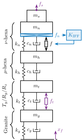
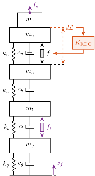
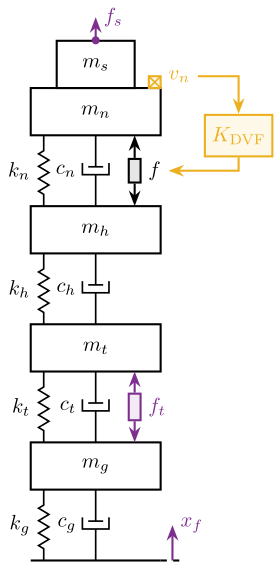
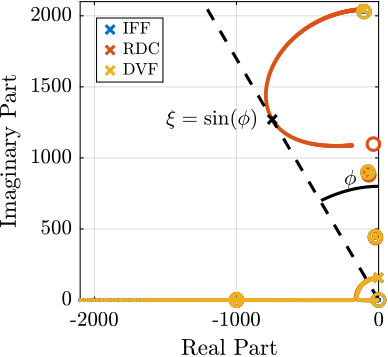
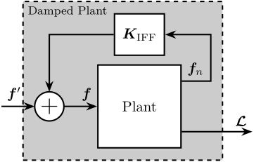
In this section, three active damping techniques are applied to the nano-hexapod (see Figure ref:fig:uniaxial_active_damping_strategies): Integral Force Feedback (IFF) cite:preumont91_activ, Relative Damping Control (RDC) cite:&preumont18_vibrat_contr_activ_struc_fourt_edition Chapter 7.2 and Direct Velocity Feedback (DVF) cite:karnopp74_vibrat_contr_using_semi_activ_force_gener,serrand00_multic_feedb_contr_isolat_base_excit_vibrat,preumont02_force_feedb_versus_accel_feedb.
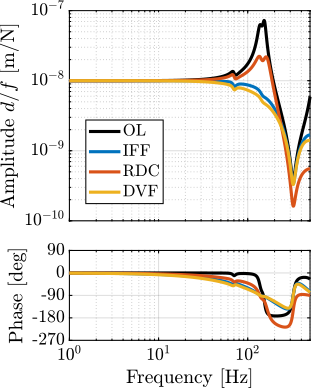
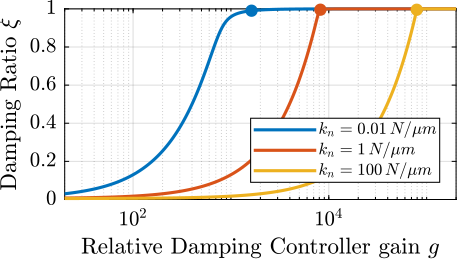
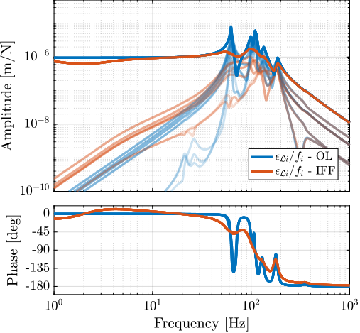
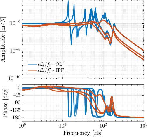
These damping strategies are first described (Section ref:ssec:uniaxial_active_damping_strategies) and are then compared in terms of achievable damping of the nano-hexapod mode (Section ref:ssec:uniaxial_active_damping_achievable_damping), reduction of the effect of disturbances (i.e., $x_f$, $f_t$ and $f_s$) on the displacement $d$ (Sections ref:ssec:uniaxial_active_damping_sensitivity_disturbances).
\begin{tikzpicture}
  % ====================
  % Parameters
  % ====================
  \def\massw{2.2}  % Width of the masses
  \def\massh{0.8}  % Height of the masses
  \def\spaceh{1.2} % Height of the springs/dampers
  \def\dispw{0.4}  % Width of the dashed line for the displacement
  \def\disph{0.3}  % Height of the arrow for the displacements
  \def\bracs{0.05} % Brace spacing vertically
  \def\brach{-12pt} % Brace shift horizontaly
  \def\fsensh{0.2} % Height of the force sensor
  \def\velsize{0.2} % Size of the velocity sensor
  % ====================

  % IFF
  \begin{scope}
    % ====================
    % Ground
    % ====================
    \draw (-0.5*\massw, 0) -- (0.5*\massw, 0);
    \draw[dashed] (0.5*\massw, 0) -- ++(\dispw, 0);
    \draw[->, color=colorpurple] (0.5*\massw+0.5*\dispw, 0) -- ++(0, 2*\disph) node[right, color=colorpurple]{$x_{f}$};
    % ====================

    % ====================
    % Granite
    \begin{scope}[shift={(0, 0)}]
      % Mass
      \draw[fill=white] (-0.5*\massw, \spaceh) rectangle (0.5*\massw, \spaceh+\massh) node[pos=0.5]{$m_{g}$};

      % Spring, Damper, and Actuator
      \draw[spring] (-0.4*\massw, 0) -- (-0.4*\massw, \spaceh) node[midway, left=0.1]{$k_{g}$};
      \draw[damper] (0, 0)           -- ( 0, \spaceh)          node[midway, left=0.2]{$c_{g}$};

      % Legend
      \draw[decorate, decoration={brace, amplitude=8pt}, xshift=\brach] %
      (-0.5*\massw, \bracs) -- (-0.5*\massw, \spaceh+\massh-\bracs) node[midway,rotate=90,anchor=south,yshift=10pt]{Granite};
    \end{scope}
    % ====================

    % ====================
    % Stages
    \begin{scope}[shift={(0, \spaceh+\massh)}]
      % Mass
      \draw[fill=white] (-0.5*\massw, \spaceh) rectangle (0.5*\massw, \spaceh+\massh) node[pos=0.5]{$m_{t}$};

      % Spring, Damper, and Actuator
      \draw[spring] (-0.4*\massw, 0) -- (-0.4*\massw, \spaceh) node[midway, left=0.1]{$k_{t}$};
      \draw[damper] (0, 0)           -- ( 0, \spaceh)          node[midway, left=0.2]{$c_{t}$};
      \draw[actuator={0.45}{0.2}{colorpurple}] ( 0.3*\massw, 0) -- (0.3*\massw, \spaceh) node[midway, right=0.1, color=colorpurple](ft){$f_{t}$};

      % Legend
      \draw[decorate, decoration={brace, amplitude=8pt}, xshift=\brach] %
      (-0.5*\massw, \bracs) -- (-0.5*\massw, \spaceh+\massh-\bracs) node[midway,rotate=90,anchor=south,yshift=10pt]{$T_y$/$R_y$/$R_z$};
    \end{scope}
    % ====================

    % ====================
    % Hexapod
    \begin{scope}[shift={(0, 2*(\spaceh+\massh))}]
      % Mass
      \draw[fill=white] (-0.5*\massw, \spaceh) rectangle (0.5*\massw, \spaceh+\massh) node[pos=0.5]{$m_h$};

      % Spring, Damper, and Actuator
      \draw[spring] (-0.4*\massw, 0) -- (-0.4*\massw, \spaceh) node[midway, left=0.1]{$k_h$};
      \draw[damper] (0, 0)           -- ( 0, \spaceh)          node[midway, left=0.2]{$c_h$};

      % Legend
      \draw[decorate, decoration={brace, amplitude=8pt}, xshift=\brach] %
      (-0.5*\massw, \bracs) -- (-0.5*\massw, \spaceh+\massh-\bracs) node[midway,rotate=90,anchor=south,yshift=10pt]{$\mu\text{-hexa}$};
    \end{scope}
    % ====================

    % ====================
    % NASS
    \begin{scope}[shift={(0, 3*(\spaceh+\massh))}]
      % Mass
      \draw[fill=white] (-0.5*\massw, \spaceh) rectangle (0.5*\massw, \spaceh+\massh) node[pos=0.5]{$m_{n}$};

      % Force Sensor
      \node[forcesensor={\massw}{\fsensh}{colorblue}] (fsensn) at (0, \spaceh-\fsensh){};
      \node[right, color=colorblue] (fn) at (fsensn.east) {$f_n$};

      % Spring, Damper, and Actuator
      \draw[spring] (-0.4*\massw, 0) -- (-0.4*\massw, \spaceh-\fsensh) node[midway, left=0.1]{$k_{n}$};
      \draw[damper] (0, 0)           -- ( 0, \spaceh-\fsensh)          node[midway, left=0.2]{$c_{n}$};
      \draw[actuator={0.4}{0.2}{black}] ( 0.3*\massw, 0) -- (	0.3*\massw, \spaceh-\fsensh) node[midway, right=0.1](f){$f$};

      % Legend
      \draw[decorate, decoration={brace, amplitude=8pt}, xshift=\brach] %
      (-0.5*\massw, \bracs) -- (-0.5*\massw, \spaceh+\massh-\bracs) node[midway,rotate=90,anchor=south,yshift=10pt]{$\nu\text{-hexa}$};
    \end{scope}
    % ====================

    % ====================
    % sample
    \begin{scope}[shift={(0, 4*(\spaceh+\massh))}]
      % Mass
      \draw[fill=white] (-0.3*\massw, 0) rectangle (0.3*\massw, \massh) node[pos=0.5]{$m_{s}$};

      % External Force
      \draw[->, color=colorpurple] (0, \massh) node[]{$\bullet$} -- ++(0, 0.5*\massh) node[right, color=colorpurple]{$f_s$};
    \end{scope}
    % ====================

    % ====================
    % IFF Control
    \node[block={2em}{2em}, right=0.3 of fn, color=colorblue, fill=colorblue!10!white] (iff) {$K_{\text{IFF}}$};
    \draw[->, draw=colorblue] (fn.east) -- (iff.west);
    \draw[->, draw=colorblue] (iff.south) |- (f.east);
    % ====================
  \end{scope}
\end{tikzpicture}\begin{tikzpicture}
% ====================
% Parameters
% ====================
\def\massw{2.2} % Width of the masses
\def\massh{0.8} % Height of the masses
\def\spaceh{1.2} % Height of the springs/dampers
\def\dispw{0.4} % Width of the dashed line for the displacement
\def\disph{0.3} % Height of the arrow for the displacements
\def\bracs{0.05} % Brace spacing vertically
\def\brach{-12pt} % Brace shift horizontaly
\def\fsensh{0.2} % Height of the force sensor
\def\velsize{0.2} % Size of the velocity sensor
% ====================
% RDC
\begin{scope}
% ====================
% Ground
% ====================
\draw (-0.5*\massw, 0) -- (0.5*\massw, 0);
\draw[dashed] (0.5*\massw, 0) -- ++(\dispw, 0);
\draw[->, color=colorpurple] (0.5*\massw+0.5*\dispw, 0) -- ++(0, 2*\disph) node[right, color=colorpurple]{$x_{f}$};
% ====================
% ====================
% Granite
\begin{scope}[shift={(0, 0)}]
% Mass
\draw[fill=white] (-0.5*\massw, \spaceh) rectangle (0.5*\massw, \spaceh+\massh) node[pos=0.5]{$m_{g}$};
% Spring, Damper, and Actuator
\draw[spring] (-0.4*\massw, 0) -- (-0.4*\massw, \spaceh) node[midway, left=0.1]{$k_{g}$};
\draw[damper] (0, 0) -- ( 0, \spaceh) node[midway, left=0.2]{$c_{g}$};
\end{scope}
% ====================
% ====================
% Stages
\begin{scope}[shift={(0, \spaceh+\massh)}]
% Mass
\draw[fill=white] (-0.5*\massw, \spaceh) rectangle (0.5*\massw, \spaceh+\massh) node[pos=0.5]{$m_{t}$};
% Spring, Damper, and Actuator
\draw[spring] (-0.4*\massw, 0) -- (-0.4*\massw, \spaceh) node[midway, left=0.1]{$k_{t}$};
\draw[damper] (0, 0) -- ( 0, \spaceh) node[midway, left=0.2]{$c_{t}$};
\draw[actuator={0.45}{0.2}{colorpurple}] ( 0.3*\massw, 0) -- (0.3*\massw, \spaceh) node[midway, right=0.1, color=colorpurple](ft){$f_{t}$};
\end{scope}
% ====================
% ====================
% Hexapod
\begin{scope}[shift={(0, 2*(\spaceh+\massh))}]
% Mass
\draw[fill=white] (-0.5*\massw, \spaceh) rectangle (0.5*\massw, \spaceh+\massh) node[pos=0.5]{$m_h$};
% Spring, Damper, and Actuator
\draw[spring] (-0.4*\massw, 0) -- (-0.4*\massw, \spaceh) node[midway, left=0.1]{$k_h$};
\draw[damper] (0, 0) -- ( 0, \spaceh) node[midway, left=0.2]{$c_h$};
\draw[dashed] (0.5*\massw, \spaceh+\massh) -- ++(2*\dispw, 0) coordinate(drbot);
\end{scope}
% ====================
% ====================
% NASS
\begin{scope}[shift={(0, 3*(\spaceh+\massh))}]
% Mass
\draw[fill=white] (-0.5*\massw, \spaceh) rectangle (0.5*\massw, \spaceh+\massh) node[pos=0.5]{$m_{n}$};
% Spring, Damper, and Actuator
\draw[spring] (-0.4*\massw, 0) -- (-0.4*\massw, \spaceh) node[midway, left=0.1]{$k_{n}$};
\draw[damper] (0, 0) -- ( 0, \spaceh) node[midway, left=0.2]{$c_{n}$};
\draw[actuator={0.4}{0.2}{black}] ( 0.3*\massw, 0) -- (0.3*\massw, \spaceh) node[midway, right=0.1](f){$f$};
\draw[dashed, draw=colorred] (0.5*\massw, \spaceh+\massh) -- ++(2*\dispw, 0) coordinate(drtop);
\end{scope}
% ====================
% ====================
% sample
\begin{scope}[shift={(0, 4*(\spaceh+\massh))}]
% Mass
\draw[fill=white] (-0.3*\massw, 0) rectangle (0.3*\massw, \massh) node[pos=0.5]{$m_{s}$};
% External Force
\draw[->, color=colorpurple] (0, \massh) node[]{$\bullet$} -- ++(0, 0.5*\massh) node[right, color=colorpurple]{$f_s$};
\end{scope}
% ====================
\draw[<->, dashed, draw=colorred] ($(drbot)+(-0.1, 0)$) -- ($(drtop)+(-0.1, 0)$) node[right, color=colorred](dr){$d\mathcal{L}$};
% ====================
% RDC Control
\node[block={2em}{2em}, below right=0.2 and -0.2 of dr, color=colorred, fill=colorred!10!white] (rdc) {$K_{\text{RDC}}$};
\draw[->, draw=colorred] (dr.east) -| (rdc.north);
\draw[->, draw=colorred] (rdc.south) |- (f.east);
% ====================
\end{scope}
\end{tikzpicture}\begin{tikzpicture}
% ====================
% Parameters
% ====================
\def\massw{2.2} % Width of the masses
\def\massh{0.8} % Height of the masses
\def\spaceh{1.2} % Height of the springs/dampers
\def\dispw{0.4} % Width of the dashed line for the displacement
\def\disph{0.3} % Height of the arrow for the displacements
\def\bracs{0.05} % Brace spacing vertically
\def\brach{-12pt} % Brace shift horizontaly
\def\fsensh{0.2} % Height of the force sensor
\def\velsize{0.2} % Size of the velocity sensor
% ====================
% DVF
\begin{scope}
% ====================
% Ground
% ====================
\draw (-0.5*\massw, 0) -- (0.5*\massw, 0);
\draw[dashed] (0.5*\massw, 0) -- ++(\dispw, 0);
\draw[->, color=colorpurple] (0.5*\massw+0.5*\dispw, 0) -- ++(0, 2*\disph) node[right, color=colorpurple]{$x_{f}$};
% ====================
% ====================
% Marble
\begin{scope}[shift={(0, 0)}]
% Mass
\draw[fill=white] (-0.5*\massw, \spaceh) rectangle (0.5*\massw, \spaceh+\massh) node[pos=0.5]{$m_{g}$};
% Spring, Damper, and Actuator
\draw[spring] (-0.4*\massw, 0) -- (-0.4*\massw, \spaceh) node[midway, left=0.1]{$k_{g}$};
\draw[damper] (0, 0) -- ( 0, \spaceh) node[midway, left=0.2]{$c_{g}$};
\end{scope}
% ====================
% ====================
% Stages
\begin{scope}[shift={(0, \spaceh+\massh)}]
% Mass
\draw[fill=white] (-0.5*\massw, \spaceh) rectangle (0.5*\massw, \spaceh+\massh) node[pos=0.5]{$m_{t}$};
% Spring, Damper, and Actuator
\draw[spring] (-0.4*\massw, 0) -- (-0.4*\massw, \spaceh) node[midway, left=0.1]{$k_{t}$};
\draw[damper] (0, 0) -- ( 0, \spaceh) node[midway, left=0.2]{$c_{t}$};
\draw[actuator={0.45}{0.2}{colorpurple}] ( 0.3*\massw, 0) -- (0.3*\massw, \spaceh) node[midway, right=0.1, color=colorpurple](ft){$f_{t}$};
\end{scope}
% ====================
% ====================
% Hexapod
\begin{scope}[shift={(0, 2*(\spaceh+\massh))}]
% Mass
\draw[fill=white] (-0.5*\massw, \spaceh) rectangle (0.5*\massw, \spaceh+\massh) node[pos=0.5]{$m_{h}$};
% Spring, Damper, and Actuator
\draw[spring] (-0.4*\massw, 0) -- (-0.4*\massw, \spaceh) node[midway, left=0.1]{$k_{h}$};
\draw[damper] (0, 0) -- ( 0, \spaceh) node[midway, left=0.2]{$c_{h}$};
\end{scope}
% ====================
% ====================
% NASS
\begin{scope}[shift={(0, 3*(\spaceh+\massh))}]
% Mass
\draw[fill=white] (-0.5*\massw, \spaceh) rectangle (0.5*\massw, \spaceh+\massh) node[pos=0.5]{$m_{n}$};
% Spring, Damper, and Actuator
\draw[spring] (-0.4*\massw, 0) -- (-0.4*\massw, \spaceh) node[midway, left=0.1]{$k_{n}$};
\draw[damper] (0, 0) -- ( 0, \spaceh) node[midway, left=0.2]{$c_{n}$};
\draw[actuator={0.4}{0.2}{black}] ( 0.3*\massw, 0) -- (0.3*\massw, \spaceh) node[midway, right=0.1](f){$f$};
% Velocity Sensor
\node[inertialsensor={\velsize}{coloryellow}] (veln) at (0.5*\massw, \spaceh+\massh) {};
\node[right, color=coloryellow] (xn) at (veln.north east) {$v_n$};
\end{scope}
% ====================
% ====================
% sample
\begin{scope}[shift={(0, 4*(\spaceh+\massh))}]
% Mass
\draw[fill=white] (-0.3*\massw, 0) rectangle (0.3*\massw, \massh) node[pos=0.5]{$m_{s}$};
% External Force
\draw[->, color=colorpurple] (0, \massh) node[]{$\bullet$} -- ++(0, 0.5*\massh) node[right, color=colorpurple]{$f_s$};
\end{scope}
% ====================
% ====================
% DVF Control
\node[block={2em}{2em}, below right=0.4 and 0.1 of xn, color=coloryellow, fill=coloryellow!10!white] (ppf) {$K_{\text{DVF}}$};
\draw[->, draw=coloryellow] (xn.east) -| (ppf.north);
\draw[->, draw=coloryellow] (ppf.south) |- (f.east);
% ====================
\end{scope}
\end{tikzpicture}Active Damping Strategies
<<ssec:uniaxial_active_damping_strategies>>
Integral Force Feedback (IFF)
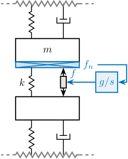
The Integral Force Feedback strategy consists of using a force sensor in series with the actuator (see Figure ref:fig:uniaxial_active_damping_iff_schematic) and applying an "integral" feedback controller eqref:eq:uniaxial_iff_controller.
\begin{equation}\label{eq:uniaxial_iff_controller} \boxed{K_{\text{IFF}}(s) = \frac{g}{s}}
\end{equation}
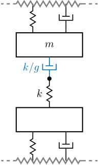
The mechanical equivalent of this IFF strategy is a dashpot in series with the actuator stiffness with a damping coefficient equal to the stiffness of the actuator divided by the controller gain $k/g$ (see Figure ref:fig:uniaxial_active_damping_iff_equiv).
\begin{tikzpicture}
  % ====================
  % Parameters
  % ====================
  \def\massw{2.2}  % Width of the masses
  \def\massh{0.8}  % Height of the masses
  \def\spaceh{1.2} % Height of the springs/dampers
  \def\dispw{0.4}  % Width of the dashed line for the displacement
  \def\disph{0.3}  % Height of the arrow for the displacements
  \def\bracs{0.05} % Brace spacing vertically
  \def\brach{-12pt} % Brace shift horizontaly
  \def\fsensh{0.2} % Height of the force sensor
  \def\velsize{0.2} % Size of the velocity sensor
  % ====================

  \begin{scope}
    % ====================
    % Stage Below
    \begin{scope}
      \draw[fill=white] (-0.5*\massw, \spaceh) rectangle (0.5*\massw, \spaceh+\massh);
      \draw[spring] (-0.25*\massw, 0) -- (-0.25*\massw, \spaceh);
      \draw[damper] ( 0.25*\massw, 0) -- ( 0.25*\massw, \spaceh);
      \draw[decorate,decoration={zigzag,segment length=6pt},draw=black!50!white,very thick] (-0.5*\massw, 0) -- (0.5*\massw, 0);
      \draw[draw=black!50!white,very thick, dashed] (-0.5*\massw, 0) -- ++(-0.5, 0);
      \draw[draw=black!50!white,very thick, dashed] ( 0.5*\massw, 0) -- ++( 0.5, 0);
    \end{scope}
    % ====================

    % ====================
    % NASS
    \begin{scope}[shift={(0, \spaceh+\massh)}]
      \draw[fill=white] (-0.5*\massw, \spaceh) rectangle (0.5*\massw, \spaceh+\massh) node[pos=0.5]{$m$};
      \node[forcesensor={\massw}{\fsensh}{colorblue}] (fsensn) at (0, \spaceh-\fsensh){};
      \node[right, color=colorblue] (fn) at (fsensn.east) {$f_n$};
      \draw[spring] (-0.25*\massw, 0) -- (-0.25*\massw, \spaceh-\fsensh) node[midway, left=0.1]{$k$};
      \draw[actuator={0.4}{0.2}{black}] ( 0.25*\massw, 0) -- (0.25*\massw, \spaceh-\fsensh) coordinate[midway, shift={(0.1,0)}](f);
    \end{scope}
    % ====================

    % ====================
    % Stage Above
    \begin{scope}[shift={(0, 2*(\spaceh+\massh))}]
      \draw[spring] (-0.25*\massw, 0) -- (-0.25*\massw, \spaceh);
      \draw[damper] ( 0.25*\massw, 0) -- ( 0.25*\massw, \spaceh);
      \draw[decorate,decoration={zigzag,segment length=6pt},draw=black!50!white,very thick] (-0.5*\massw, \spaceh) -- (0.5*\massw, \spaceh);
      \draw[draw=black!50!white,very thick, dashed] (-0.5*\massw, \spaceh) -- ++(-0.5, 0);
      \draw[draw=black!50!white,very thick, dashed] ( 0.5*\massw, \spaceh) -- ++( 0.5, 0);
    \end{scope}
    % ====================

    % ====================
    % IFF Control
    \node[block={2em}{2em}, right=1.0 of f, color=colorblue, fill=colorblue!10!white] (iff) {$g/s$};
    \draw[->, draw=colorblue] (fn.east) -- ++(1.0, 0) |- (iff.east);
    \draw[->, draw=colorblue] (iff.west) -- (f.east) node[above right, color=colorblue]{$f$};
    % ====================
  \end{scope}
\end{tikzpicture}\begin{tikzpicture}
% ====================
% Parameters
% ====================
\def\massw{2.2} % Width of the masses
\def\massh{0.8} % Height of the masses
\def\spaceh{1.2} % Height of the springs/dampers
\def\dispw{0.4} % Width of the dashed line for the displacement
\def\disph{0.3} % Height of the arrow for the displacements
\def\bracs{0.05} % Brace spacing vertically
\def\brach{-12pt} % Brace shift horizontaly
\def\fsensh{0.2} % Height of the force sensor
\def\velsize{0.2} % Size of the velocity sensor
% ====================
\begin{scope}[shift={(6, 0)}]
% ====================
% Stage Below
\begin{scope}
\draw[fill=white] (-0.5*\massw, 0.8*\spaceh) rectangle (0.5*\massw, 0.8*\spaceh+\massh);
\draw[spring] (-0.25*\massw, 0) -- (-0.25*\massw, 0.8*\spaceh);
\draw[damper] ( 0.25*\massw, 0) -- ( 0.25*\massw, 0.8*\spaceh);
\draw[decorate,decoration={zigzag,segment length=6pt},draw=black!50!white,very thick] (-0.5*\massw, 0) -- (0.5*\massw, 0);
\draw[draw=black!50!white,very thick, dashed] (-0.5*\massw, 0) -- ++(-0.5, 0);
\draw[draw=black!50!white,very thick, dashed] ( 0.5*\massw, 0) -- ++( 0.5, 0);
\end{scope}
% ====================
% ====================
% NASS
\begin{scope}[shift={(0, 0.8*\spaceh+\massh)}]
\draw[fill=white] (-0.5*\massw, 1.4*\spaceh) rectangle (0.5*\massw, 1.4*\spaceh+\massh) node[pos=0.5]{$m$};
\draw[spring] (0, 0) -- node[midway, left=0.1]{$k$} (0, 0.8*\spaceh);
\draw[damper={colorblue}{}{}] (0, 0.8*\spaceh) node[branch]{} -- (0, 1.4*\spaceh) node[midway, left=0.2, color=colorblue]{$k/g$};
\end{scope}
% ====================
% ====================
% Stage Above
\begin{scope}[shift={(0, 0.8*\spaceh+\massh+1.4*\spaceh+\massh)}]
\draw[spring] (-0.25*\massw, 0) -- (-0.25*\massw, 0.8*\spaceh);
\draw[damper] ( 0.25*\massw, 0) -- ( 0.25*\massw, 0.8*\spaceh);
\draw[decorate,decoration={zigzag,segment length=6pt},draw=black!50!white,very thick] (-0.5*\massw, 0.8*\spaceh) -- (0.5*\massw, 0.8*\spaceh);
\draw[draw=black!50!white,very thick, dashed] (-0.5*\massw, 0.8*\spaceh) -- ++(-0.5, 0);
\draw[draw=black!50!white,very thick, dashed] ( 0.5*\massw, 0.8*\spaceh) -- ++( 0.5, 0);
\end{scope}
% ====================
\end{scope}
% % Equiv
% \draw[double, <->, draw=colorblue, double distance=1.5] (3.0, 1.5*\spaceh+\massh) -- ++(1.5,0);
\end{tikzpicture}Relative Damping Control (RDC)
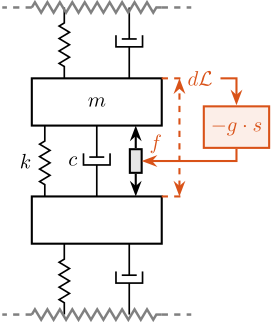
For the Relative Damping Control strategy, a relative motion sensor that measures the motion of the actuator is used (see Figure ref:fig:uniaxial_active_damping_rdc_schematic) and a "derivative" feedback controller is used eqref:eq:uniaxial_rdc_controller.
\begin{equation}\label{eq:uniaxial_rdc_controller} \boxed{K_{\text{RDC}}(s) = - g ⋅ s}
\end{equation}
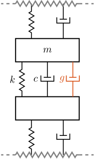
The mechanical equivalent of acrshort:rdc is a dashpot in parallel with the actuator with a damping coefficient equal to the controller gain $g$ (see Figure ref:fig:uniaxial_active_damping_rdc_equiv).
\begin{tikzpicture}
  % ====================
  % Parameters
  % ====================
  \def\massw{2.2}  % Width of the masses
  \def\massh{0.8}  % Height of the masses
  \def\spaceh{1.2} % Height of the springs/dampers
  \def\dispw{0.4}  % Width of the dashed line for the displacement
  \def\disph{0.3}  % Height of the arrow for the displacements
  \def\bracs{0.05} % Brace spacing vertically
  \def\brach{-12pt} % Brace shift horizontaly
  \def\fsensh{0.2} % Height of the force sensor
  \def\velsize{0.2} % Size of the velocity sensor
  % ====================

  \begin{scope}
    % ====================
    % Stage Below
    \begin{scope}
      \draw[fill=white] (-0.5*\massw, \spaceh) rectangle (0.5*\massw, \spaceh+\massh);
      \draw[spring] (-0.25*\massw, 0) -- (-0.25*\massw, \spaceh);
      \draw[damper] ( 0.25*\massw, 0) -- ( 0.25*\massw, \spaceh);

      \draw[dashed, draw=colorred] (0.5*\massw, \spaceh+\massh) -- ++(1*\dispw, 0) coordinate(drbot);
      \draw[decorate,decoration={zigzag,segment length=6pt},draw=black!50!white,very thick] (-0.5*\massw, 0) -- (0.5*\massw, 0);
      \draw[draw=black!50!white,very thick, dashed] (-0.5*\massw, 0) -- ++(-0.5, 0);
      \draw[draw=black!50!white,very thick, dashed] ( 0.5*\massw, 0) -- ++( 0.5, 0);
    \end{scope}
    % ====================

    % ====================
    % NASS
    \begin{scope}[shift={(0, \spaceh+\massh)}]
      \draw[fill=white] (-0.5*\massw, \spaceh) rectangle (0.5*\massw, \spaceh+\massh) node[pos=0.5]{$m$};
      \draw[spring] (-0.4*\massw, 0) -- (-0.4*\massw, \spaceh) node[midway, left=0.1]{$k$};
      \draw[damper] (0, 0)           -- ( 0, \spaceh)          node[midway, left=0.2]{$c$};
      \draw[actuator={0.4}{0.2}{black}] ( 0.3*\massw, 0) -- (0.3*\massw, \spaceh) coordinate[midway, shift={(0.1,0)}](f);

      \draw[dashed, draw=colorred] (0.5*\massw, \spaceh+\massh) -- ++(1*\dispw, 0) coordinate(drtop);
    \end{scope}
    % ====================

    % ====================
    % Stage Above
    \begin{scope}[shift={(0, 2*(\spaceh+\massh))}]
      \draw[spring] (-0.25*\massw, 0) -- (-0.25*\massw, \spaceh);
      \draw[damper] ( 0.25*\massw, 0) -- ( 0.25*\massw, \spaceh);

      \draw[decorate,decoration={zigzag,segment length=6pt},draw=black!50!white,very thick] (-0.5*\massw, \spaceh) -- (0.5*\massw, \spaceh);
      \draw[draw=black!50!white,very thick, dashed] (-0.5*\massw, \spaceh) -- ++(-0.5, 0);
      \draw[draw=black!50!white,very thick, dashed] ( 0.5*\massw, \spaceh) -- ++( 0.5, 0);
    \end{scope}
    % ====================

    \draw[<->, dashed, draw=colorred] ($(drbot)+(-0.1, 0)$) -- ($(drtop)+(-0.1, 0)$) node[right, color=colorred](dr){$d\mathcal{L}$};
    % ====================
    % RDC Control
    \node[block={2em}{2em}, below right=0.2 and -0.3 of dr, color=colorred, fill=colorred!10!white] (rdc) {$-g \cdot s$};
    \draw[->, draw=colorred] (dr.east) -| (rdc.north);
    \draw[->, draw=colorred] (rdc.south) |- (f.east) node[above right, color=colorred]{$f$};
    % ====================
  \end{scope}
\end{tikzpicture}\begin{tikzpicture}
% ====================
% Parameters
% ====================
\def\massw{2.2} % Width of the masses
\def\massh{0.8} % Height of the masses
\def\spaceh{1.2} % Height of the springs/dampers
\def\dispw{0.4} % Width of the dashed line for the displacement
\def\disph{0.3} % Height of the arrow for the displacements
\def\bracs{0.05} % Brace spacing vertically
\def\brach{-12pt} % Brace shift horizontaly
\def\fsensh{0.2} % Height of the force sensor
\def\velsize{0.2} % Size of the velocity sensor
% ====================
\begin{scope}
% ====================
% Stage Below
\begin{scope}
\draw[fill=white] (-0.5*\massw, \spaceh) rectangle (0.5*\massw, \spaceh+\massh);
\draw[spring] (-0.25*\massw, 0) -- (-0.25*\massw, \spaceh);
\draw[damper] ( 0.25*\massw, 0) -- ( 0.25*\massw, \spaceh);
\draw[decorate,decoration={zigzag,segment length=6pt},draw=black!50!white,very thick] (-0.5*\massw, 0) -- (0.5*\massw, 0);
\draw[draw=black!50!white,very thick, dashed] (-0.5*\massw, 0) -- ++(-0.5, 0);
\draw[draw=black!50!white,very thick, dashed] ( 0.5*\massw, 0) -- ++( 0.5, 0);
\end{scope}
% ====================
% ====================
% NASS
\begin{scope}[shift={(0, \spaceh+\massh)}]
\draw[fill=white] (-0.5*\massw, \spaceh) rectangle (0.5*\massw, \spaceh+\massh) node[pos=0.5]{$m$};
\draw[spring] (-0.4*\massw, 0) -- (-0.4*\massw, \spaceh) node[midway, left=0.1]{$k$};
\draw[damper] (0, 0) -- ( 0, \spaceh) node[midway, left=0.2]{$c$};
\draw[damper={colorred}{}{}] ( 0.4*\massw, 0) -- ( 0.4*\massw, \spaceh) node[midway, left=0.15, color=colorred]{$g$};
\end{scope}
% ====================
% ====================
% Stage Above
\begin{scope}[shift={(0, 2*(\spaceh+\massh))}]
\draw[spring] (-0.25*\massw, 0) -- (-0.25*\massw, \spaceh);
\draw[damper] ( 0.25*\massw, 0) -- ( 0.25*\massw, \spaceh);
\draw[decorate,decoration={zigzag,segment length=6pt},draw=black!50!white,very thick] (-0.5*\massw, \spaceh) -- (0.5*\massw, \spaceh);
\draw[draw=black!50!white,very thick, dashed] (-0.5*\massw, \spaceh) -- ++(-0.5, 0);
\draw[draw=black!50!white,very thick, dashed] ( 0.5*\massw, \spaceh) -- ++( 0.5, 0);
\end{scope}
% ====================
\end{scope}
% % Equiv
% \draw[double, <->, draw=colorred, double distance=1.5] (3.0, 1.5*\spaceh+\massh) -- ++(1.5,0);
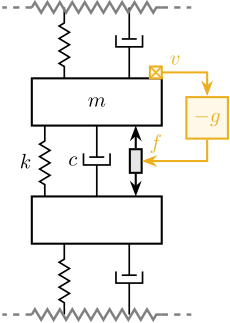
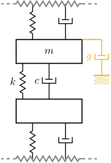
\end{tikzpicture}Direct Velocity Feedback (DVF)
Finally, the direct velocity feedback strategy consists of using an inertial sensor (usually a geophone) that measures the "absolute" velocity of the body fixed on top of the actuator (see Figure ref:fig:uniaxial_active_damping_dvf_schematic). This velocity is fed back to the actuator with a "proportional" controller eqref:eq:uniaxial_dvf_controller.
\begin{equation}\label{eq:uniaxial_dvf_controller} \boxed{K_{\text{DVF}}(s) = - g}
\end{equation}
This is equivalent to a dashpot (with a damping coefficient equal to the controller gain $g$) between the body (on which the inertial sensor is fixed) and an inertial reference frame (see Figure ref:fig:uniaxial_active_damping_dvf_equiv). This is usually referred to as "sky hook damper".
\begin{tikzpicture}
  % ====================
  % Parameters
  % ====================
  \def\massw{2.2}  % Width of the masses
  \def\massh{0.8}  % Height of the masses
  \def\spaceh{1.2} % Height of the springs/dampers
  \def\dispw{0.4}  % Width of the dashed line for the displacement
  \def\disph{0.3}  % Height of the arrow for the displacements
  \def\bracs{0.05} % Brace spacing vertically
  \def\brach{-12pt} % Brace shift horizontaly
  \def\fsensh{0.2} % Height of the force sensor
  \def\velsize{0.2} % Size of the velocity sensor
  % ====================

  \begin{scope}
    % ====================
    % Stage Below
    \begin{scope}
      \draw[fill=white] (-0.5*\massw, \spaceh) rectangle (0.5*\massw, \spaceh+\massh);
      \draw[spring] (-0.25*\massw, 0) -- (-0.25*\massw, \spaceh);
      \draw[damper] ( 0.25*\massw, 0) -- ( 0.25*\massw, \spaceh);

      \draw[decorate,decoration={zigzag,segment length=6pt},draw=black!50!white,very thick] (-0.5*\massw, 0) -- (0.5*\massw, 0);
      \draw[draw=black!50!white,very thick, dashed] (-0.5*\massw, 0) -- ++(-0.5, 0);
      \draw[draw=black!50!white,very thick, dashed] ( 0.5*\massw, 0) -- ++( 0.5, 0);
    \end{scope}
    % ====================

    % ====================
    % NASS
    \begin{scope}[shift={(0, \spaceh+\massh)}]
      \draw[fill=white] (-0.5*\massw, \spaceh) rectangle (0.5*\massw, \spaceh+\massh) node[pos=0.5]{$m$};
      \draw[spring] (-0.4*\massw, 0) -- (-0.4*\massw, \spaceh) node[midway, left=0.1]{$k$};
      \draw[damper] (0, 0)           -- ( 0, \spaceh)          node[midway, left=0.2]{$c$};
      \draw[actuator={0.4}{0.2}{black}] ( 0.3*\massw, 0) -- (0.3*\massw, \spaceh) coordinate[midway, shift={(0.1,0)}](f);

      % Velocity Sensor
      \node[inertialsensor={\velsize}{coloryellow}] (veln) at (0.5*\massw, \spaceh+\massh) {};
    \end{scope}
    % ====================

    % ====================
    % Stage Above
    \begin{scope}[shift={(0, 2*(\spaceh+\massh))}]
      \draw[spring] (-0.25*\massw, 0) -- (-0.25*\massw, \spaceh);
      \draw[damper] ( 0.25*\massw, 0) -- ( 0.25*\massw, \spaceh);

      \draw[decorate,decoration={zigzag,segment length=6pt},draw=black!50!white,very thick] (-0.5*\massw, \spaceh) -- (0.5*\massw, \spaceh);
      \draw[draw=black!50!white,very thick, dashed] (-0.5*\massw, \spaceh) -- ++(-0.5, 0);
      \draw[draw=black!50!white,very thick, dashed] ( 0.5*\massw, \spaceh) -- ++( 0.5, 0);
    \end{scope}
    % ====================

    % ====================
    % DVF Control
    \node[block={2em}{2em}, below right=0.3 and 0.4 of veln, color=coloryellow, fill=coloryellow!10!white] (ppf) {$-g$};
    \draw[->, draw=coloryellow] (veln.east) node[above right, color=coloryellow]{$v$} -| (ppf.north);
    \draw[->, draw=coloryellow] (ppf.south) |- (f.east) node[above right, color=coloryellow]{$f$};
    % ====================
  \end{scope}
\end{tikzpicture}\begin{tikzpicture}
% ====================
% Parameters
% ====================
\def\massw{2.2} % Width of the masses
\def\massh{0.8} % Height of the masses
\def\spaceh{1.2} % Height of the springs/dampers
\def\dispw{0.4} % Width of the dashed line for the displacement
\def\disph{0.3} % Height of the arrow for the displacements
\def\bracs{0.05} % Brace spacing vertically
\def\brach{-12pt} % Brace shift horizontaly
\def\fsensh{0.2} % Height of the force sensor
\def\velsize{0.2} % Size of the velocity sensor
% ====================
\begin{scope}
% ====================
% Stage Below
\begin{scope}
\draw[fill=white] (-0.5*\massw, \spaceh) rectangle (0.5*\massw, \spaceh+\massh);
\draw[spring] (-0.25*\massw, 0) -- (-0.25*\massw, \spaceh);
\draw[damper] ( 0.25*\massw, 0) -- ( 0.25*\massw, \spaceh);
\draw[decorate,decoration={zigzag,segment length=6pt},draw=black!50!white,very thick] (-0.5*\massw, 0) -- (0.5*\massw, 0);
\draw[draw=black!50!white,very thick, dashed] (-0.5*\massw, 0) -- ++(-0.5, 0);
\draw[draw=black!50!white,very thick, dashed] ( 0.5*\massw, 0) -- ++( 0.5, 0);
\end{scope}
% ====================
% ====================
% NASS
\begin{scope}[shift={(0, \spaceh+\massh)}]
\draw[fill=white] (-0.5*\massw, \spaceh) rectangle (0.5*\massw, \spaceh+\massh) node[pos=0.5]{$m$};
\draw[spring] (-0.4*\massw, 0) -- (-0.4*\massw, \spaceh) node[midway, left=0.1]{$k$};
\draw[damper] (0, 0) -- ( 0, \spaceh) node[midway, left=0.2]{$c$};
\draw[damper={coloryellow}{}{}] ( 0.8*\massw, \massh) -- ( 0.8*\massw, \massh+\spaceh)node[midway, left=0.2, color=coloryellow]{$g$};
\draw[draw=coloryellow] (0.5*\massw, \massh+\spaceh) -- ( 0.8*\massw, \massh+\spaceh);
\node[mground={0.5}{0.3}{coloryellow}] at (0.8*\massw, \massh);
\end{scope}
% ====================
% ====================
% Stage Above
\begin{scope}[shift={(0, 2*(\spaceh+\massh))}]
\draw[spring] (-0.25*\massw, 0) -- (-0.25*\massw, \spaceh);
\draw[damper] ( 0.25*\massw, 0) -- ( 0.25*\massw, \spaceh);
\draw[decorate,decoration={zigzag,segment length=6pt},draw=black!50!white,very thick] (-0.5*\massw, \spaceh) -- (0.5*\massw, \spaceh);
\draw[draw=black!50!white,very thick, dashed] (-0.5*\massw, \spaceh) -- ++(-0.5, 0);
\draw[draw=black!50!white,very thick, dashed] ( 0.5*\massw, \spaceh) -- ++( 0.5, 0);
\end{scope}
% ====================
\end{scope}
% % Equiv
% \draw[double, <->, draw=coloryellow, double distance=1.5] (2.5, 1.5*\spaceh+\massh) -- ++(1.5,0);
\end{tikzpicture}Plant Dynamics for Active Damping
<<ssec:uniaxial_active_damping_plants>> The plant dynamics for all three active damping techniques are shown in Figure ref:fig:uniaxial_plant_active_damping_techniques. All have alternating poles and zeros meaning that the phase does not vary by more than $180\,\text{deg}$ which makes the design of a robust damping controller very easy.
This alternating poles and zeros property is guaranteed for the IFF and RDC cases because the sensors are collocated with the actuator cite:&preumont18_vibrat_contr_activ_struc_fourt_edition Chapter 7. For the DVF controller, this property is not guaranteed, and may be lost if some flexibility between the nano-hexapod and the sample is considered cite:&preumont18_vibrat_contr_activ_struc_fourt_edition Chapter 8.4.
When the nano-hexapod's suspension modes are at frequencies lower than the resonances of the micro-station (blue and red curves in Figure ref:fig:uniaxial_plant_active_damping_techniques), the resonances of the micro-stations have little impact on the IFF and DVF transfer functions. For the stiff nano-hexapod (yellow curves), the micro-station dynamics can be seen on the transfer functions in Figure ref:fig:uniaxial_plant_active_damping_techniques. Therefore, it is expected that the micro-station dynamics might impact the achievable damping if a stiff nano-hexapod is used.
Achievable Damping and Damped Plants
<<ssec:uniaxial_active_damping_achievable_damping>>
To compare the added damping using the three considered active damping strategies, the root locus plot is used. Indeed, the damping ratio $\xi$ of a pole in the complex plane can be estimated from the angle $\phi$ it makes with the imaginary axis eqref:eq:uniaxial_damping_ratio_angle. Increasing the angle with the imaginary axis therefore means that more damping is added to the considered resonance. This is illustrated in Figure ref:fig:uniaxial_root_locus_damping_techniques_micro_station_mode by the dashed black line indicating the maximum achievable damping.
\begin{equation}\label{eq:uniaxial_damping_ratio_angle} ξ = sin(ɸ)
\end{equation}
The Root Locus for the three nano-hexapod stiffnesses and the three active damping techniques are shown in Figure ref:fig:uniaxial_root_locus_damping_techniques. All three active damping approaches can lead to critical damping of the nano-hexapod suspension mode (angle $\phi$ can be increased up to 90 degrees). There is even some damping authority on micro-station modes in the following cases:
- IFF with a stiff nano-hexapod (Figure ref:fig:uniaxial_root_locus_damping_techniques_stiff)
- This can be understood from the mechanical equivalent of IFF shown in Figure ref:fig:uniaxial_active_damping_iff_equiv considering an high stiffness $k$. The micro-station top platform is connected to an inertial mass (the nano-hexapod) through a damper, which dampens the micro-station suspension suspension mode.
- DVF with a stiff nano-hexapod (Figure ref:fig:uniaxial_root_locus_damping_techniques_stiff)
- In that case, the "sky hook damper" (see mechanical equivalent of DVF in Figure ref:fig:uniaxial_active_damping_dvf_equiv) is connected to the micro-station top platform through the stiff nano-hexapod.
- RDC with a soft nano-hexapod (Figure ref:fig:uniaxial_root_locus_damping_techniques_micro_station_mode)
- At the frequency of the micro-station mode, the nano-hexapod top mass behaves as an inertial reference because the suspension mode of the soft nano-hexapod is at much lower frequency. The micro-station and the nano-hexapod masses are connected through a large damper induced by RDC (see mechanical equivalent in Figure ref:fig:uniaxial_active_damping_rdc_equiv) which allows some damping of the micro-station.
The transfer functions from the plant input $f$ to the relative displacement $d$ while active damping is implemented are shown in Figure ref:fig:uniaxial_damped_plant_three_active_damping_techniques. All three active damping techniques yielded similar damped plants.
Sensitivity to disturbances and Noise Budgeting
<<ssec:uniaxial_active_damping_sensitivity_disturbances>>
Reasonable gains are chosen for the three active damping strategies such that the nano-hexapod suspension mode is well damped. The sensitivity to disturbances (direct forces $f_s$, stage vibrations $f_t$ and floor motion $x_f$) for all three active damping techniques are compared in Figure ref:fig:uniaxial_sensitivity_dist_active_damping. The comparison is done with the nano-hexapod having a stiffness $k_n = 1\,N/\mu m$.
Several conclusions can be drawn by comparing the obtained sensitivity transfer functions:
- IFF degrades the sensitivity to direct forces on the sample (i.e., the compliance) below the resonance of the nano-hexapod (Figure ref:fig:uniaxial_sensitivity_dist_active_damping_fs). This is a well-known effect of using IFF for vibration isolation cite:&collette15_sensor_fusion_method_high_perfor.
- RDC degrades the sensitivity to stage vibrations around the nano-hexapod's resonance as compared to the other two methods (Figure ref:fig:uniaxial_sensitivity_dist_active_damping_ft). This is because the equivalent damper in parallel with the actuator (see Figure ref:fig:uniaxial_active_damping_rdc_equiv) increases the transmission of the micro-station vibration to the sample which is not the same for the other two active damping strategies.
- both IFF and DVF degrade the sensitivity to floor motion below the resonance of the nano-hexapod (Figure ref:fig:uniaxial_sensitivity_dist_active_damping_xf).
From the amplitude spectral density of the disturbances (computed in Section ref:sec:uniaxial_disturbances) and the sensitivity to disturbances estimated using the three active damping strategies, a noise budget can be calculated. The cumulative amplitude spectrum of the distance $d$ with all three active damping techniques is shown in Figure ref:fig:uniaxial_cas_active_damping and compared with the open-loop case. All three active damping methods give similar results.
Conclusion
Three active damping strategies have been studied for the acrfull:nass. Equivalent mechanical representations were derived in Section ref:ssec:uniaxial_active_damping_strategies which are helpful for understanding the specific effects of each strategy. The plant dynamics were then compared in Section ref:ssec:uniaxial_active_damping_plants and were found to all have alternating poles and zeros, which helps in the design of the active damping controller. However, this property is not guaranteed for DVF. The achievable damping of the nano-hexapod suspension mode can be made as large as possible for all three active damping techniques (Section ref:ssec:uniaxial_active_damping_achievable_damping). Even some damping can be applied to some micro-station modes in specific cases. The obtained damped plants were found to be similar. The damping strategies were then compared in terms of disturbance reduction in Section ref:ssec:uniaxial_active_damping_sensitivity_disturbances.
The comparison between the three active damping strategies is summarized in Table ref:tab:comp_active_damping. It is difficult to conclude on the best active damping strategy for the acrfull:nass yet. Which one will be used will be determined by the use of more accurate models and will depend on which is the easiest to implement in practice
| IFF | RDC | DVF | |
|---|---|---|---|
| Sensor | Force sensor | Relative motion sensor | Inertial sensor |
| Damping | Up to critical | Up to critical | Up to Critical |
| Robustness | Requires collocation | Requires collocation | Impacted by geophone resonances |
| $f_s$ Disturbance | $\nearrow$ at low frequency | $\searrow$ near resonance | $\searrow$ near resonance |
| $f_t$ Disturbance | $\searrow$ near resonance | $\nearrow$ near resonance | $\searrow$ near resonance |
| $x_f$ Disturbance | $\nearrow$ at low frequency | $\searrow$ near resonance | $\nearrow$ at low frequency |
Position Feedback Controller
<<sec:uniaxial_position_control>>
Introduction
The gls:haclac architecture is shown in Figure ref:fig:uniaxial_hac_lac_architecture. This corresponds to a two step control strategy:
- First, an active damping controller $\bm{K}_{\textsc{LAC}}$ is implemented (see Section ref:sec:uniaxial_active_damping). It allows the vibration level to be reduced, and it also makes the damped plant (transfer function from $u^{\prime}$ to $y$) easier to control than the undamped plant (transfer function from $u$ to $y$). This is called low authority control as it only slightly affects the system poles cite:&preumont18_vibrat_contr_activ_struc_fourt_edition Chapter 14.6.
- Then, a position controller $\bm{K}_{\textsc{HAC}}$ is implemented and is used to control the position $d$. This is called high authority control as it usually relocates the system's poles.
In this section, Integral Force Feedback is used as the Low Authority Controller (the other two damping strategies would lead to the same conclusions here). This control architecture applied to the uniaxial model is shown in Figure ref:fig:uniaxial_hac_lac_model.
\begin{tikzpicture}
  % Blocs
  \node[block={3.0cm}{3.0cm}] (P) {Plant};
  \coordinate[] (input)   at ($(P.south west)!0.5!(P.north west)$);
  \coordinate[] (outputH) at ($(P.south east)!0.2!(P.north east)$);
  \coordinate[] (outputL) at ($(P.south east)!0.8!(P.north east)$);

  \node[block, above=0.4 of P] (Klac) {$\bm{K}_{\textsc{LAC}}$};
  \node[addb, left=0.6 of input] (addF) {};
  \node[block, left=1.0 of addF] (Khac) {$\bm{K}_{\textsc{HAC}}$};
  \node[addb={+}{}{}{}{-}, left=0.6 of Khac] (subr) {};

  % Connections and labels
  \draw[->] (outputL) -- ++(0.6, 0) coordinate(eastlac) |- (Klac.east);
  \node[above right] at (outputL){$y^{\prime}$};
  \draw[->] (Klac.west) -| (addF.north);
  \draw[->] (addF.east) -- (input) node[above left]{$u$};

  \draw[<-] (subr.west) --node[midway, above]{$r$} ++(-0.8, 0);
  \draw[->] (outputH) -- ++(1.6, 0);
  \draw[->] ($(outputH) + (1.2, 0)$)node[branch]{} node[above]{$y$} -- ++(0, -1.2) -| (subr.south);
  \draw[->] (subr.east) -- (Khac.west) node[above left]{$\epsilon$};
  \draw[->] (Khac.east) -- (addF.west) node[above left=0 and 0.2]{$u^{\prime}$};

  \begin{scope}[on background layer]
    \node[fit={(Klac.north-|eastlac) (addF.west|-P.south)}, fill=black!20!white, draw, dashed, inner sep=6pt] (Pi) {};
    \node[anchor={north west}] at (Pi.north west){\small Damped Plant};
  \end{scope}
\end{tikzpicture}\begin{tikzpicture}
% ====================
% Parameters
% ====================
\def\massw{2.2} % Width of the masses
\def\massh{0.8} % Height of the masses
\def\spaceh{1.2} % Height of the springs/dampers
\def\dispw{0.4} % Width of the dashed line for the displacement
\def\disph{0.3} % Height of the arrow for the displacements
\def\bracs{0.05} % Brace spacing vertically
\def\brach{-12pt} % Brace shift horizontaly
\def\fsensh{0.2} % Height of the force sensor
\def\velsize{0.2} % Size of the velocity sensor
% ====================
% IFF
% ====================
% Ground
% ====================
\draw (-0.5*\massw, 0) -- (0.5*\massw, 0);
\draw[dashed] (0.5*\massw, 0) -- ++(\dispw, 0);
\draw[->, color=colorpurple] (0.5*\massw+0.5*\dispw, 0) -- ++(0, 2*\disph) node[right, color=colorpurple]{$x_{f}$};
% ====================
% ====================
% Granite
\begin{scope}[shift={(0, 0)}]
% Mass
\draw[fill=white] (-0.5*\massw, \spaceh) rectangle (0.5*\massw, \spaceh+\massh) node[pos=0.5]{$m_{g}$};
% Spring, Damper, and Actuator
\draw[spring] (-0.4*\massw, 0) -- (-0.4*\massw, \spaceh) node[midway, left=0.1]{$k_{g}$};
\draw[damper] (0, 0) -- ( 0, \spaceh) node[midway, left=0.2]{$c_{g}$};
% Legend
\draw[decorate, decoration={brace, amplitude=8pt}, xshift=\brach] %
(-0.5*\massw, \bracs) -- (-0.5*\massw, \spaceh+\massh-\bracs) node[midway,rotate=90,anchor=south,yshift=10pt]{Granite};
% Displacements
\draw[dashed] (0.5*\massw, \spaceh+\massh) -- ++(7.5*\dispw, 0) coordinate(xg);
\end{scope}
% ====================
% ====================
% Stages
\begin{scope}[shift={(0, \spaceh+\massh)}]
% Mass
\draw[fill=white] (-0.5*\massw, \spaceh) rectangle (0.5*\massw, \spaceh+\massh) node[pos=0.5]{$m_{t}$};
% Spring, Damper, and Actuator
\draw[spring] (-0.4*\massw, 0) -- (-0.4*\massw, \spaceh) node[midway, left=0.1]{$k_{t}$};
\draw[damper] (0, 0) -- ( 0, \spaceh) node[midway, left=0.2]{$c_{t}$};
\draw[actuator={0.45}{0.2}{colorpurple}] ( 0.3*\massw, 0) -- (0.3*\massw, \spaceh) node[midway, right=0.1, color=colorpurple](ft){$f_{t}$};
% Legend
\draw[decorate, decoration={brace, amplitude=8pt}, xshift=\brach] %
(-0.5*\massw, \bracs) -- (-0.5*\massw, \spaceh+\massh-\bracs) node[midway,rotate=90,anchor=south,yshift=10pt]{$T_y$/$R_y$/$R_z$};
\end{scope}
% ====================
% ====================
% Hexapod
\begin{scope}[shift={(0, 2*(\spaceh+\massh))}]
% Mass
\draw[fill=white] (-0.5*\massw, \spaceh) rectangle (0.5*\massw, \spaceh+\massh) node[pos=0.5]{$m_h$};
% Spring, Damper, and Actuator
\draw[spring] (-0.4*\massw, 0) -- (-0.4*\massw, \spaceh) node[midway, left=0.1]{$k_h$};
\draw[damper] (0, 0) -- ( 0, \spaceh) node[midway, left=0.2]{$c_h$};
% Legend
\draw[decorate, decoration={brace, amplitude=8pt}, xshift=\brach] %
(-0.5*\massw, \bracs) -- (-0.5*\massw, \spaceh+\massh-\bracs) node[midway,rotate=90,anchor=south,yshift=10pt]{$\mu\text{-hexa}$};
\end{scope}
% ====================
% ====================
% NASS
\begin{scope}[shift={(0, 3*(\spaceh+\massh))}]
% Mass
\draw[fill=white] (-0.5*\massw, \spaceh) rectangle (0.5*\massw, \spaceh+\massh) node[pos=0.5]{$m_{n}$};
% Force Sensor
\node[forcesensor={\massw}{\fsensh}{colorblue}] (fsensn) at (0, \spaceh-\fsensh){};
\node[right, color=colorblue] (fn) at (fsensn.east) {$f_n$};
% Spring, Damper, and Actuator
\draw[spring] (-0.4*\massw, 0) -- (-0.4*\massw, \spaceh-\fsensh) node[midway, left=0.1]{$k_{n}$};
\draw[damper] (0, 0) -- ( 0, \spaceh-\fsensh) node[midway, left=0.2]{$c_{n}$};
\draw[actuator={0.4}{0.2}{black}] ( 0.3*\massw, 0) -- ( 0.3*\massw, \spaceh-\fsensh) node[midway, right=0.1](f){$f$};
% Legend
\draw[decorate, decoration={brace, amplitude=8pt}, xshift=\brach] %
(-0.5*\massw, \bracs) -- (-0.5*\massw, \spaceh+\massh-\bracs) node[midway,rotate=90,anchor=south,yshift=10pt]{$\nu\text{-hexa}$};
% Displacements
\draw[dashed] (0.5*\massw, \spaceh+\massh) -- ++(7.5*\dispw, 0) coordinate(xnpos);
\end{scope}
% ====================
% ====================
% sample
\begin{scope}[shift={(0, 4*(\spaceh+\massh))}]
% Mass
\draw[fill=white] (-0.3*\massw, 0) rectangle (0.3*\massw, \massh) node[pos=0.5]{$m_{s}$};
% External Force
\draw[->, color=colorpurple] (0, \massh) node[]{$\bullet$} -- ++(0, 0.5*\massh) node[right, color=colorpurple]{$f_s$};
\end{scope}
% ====================
% Measured displacement
\draw[<->, dashed, draw=colorred] ($(xg)+(-0.1, 0)$) -- node[left, color=colorred](d){$d$} ($(xnpos)+(-0.1, 0)$);
% ====================
% IFF Control
\node[block={2em}{2em}, right=1.0 of fn, color=colorblue, fill=colorblue!10!white] (iff) {$K_{\textsc{IFF}}$};
\node[addb, right=0.5 of f.east] (ctrladd) {};
\node[block={2em}{2em}, color=colorred, fill=colorred!10!white] (Khac) at (ctrladd|-d) {$K_{\textsc{HAC}}$};
\draw[->, draw=colorblue] (fn.east) -- (iff.west);
\draw[->, draw=colorblue] (iff.south) |- (ctrladd.east);
\draw[->] (ctrladd.west) -- (f.east);
\draw[->, draw=colorred] (d.west) -- (Khac.east);
\draw[->, draw=colorred] (Khac.north) -- (ctrladd.south) node[below right, color=colorred]{$f^{\prime}$};
% ====================
\end{tikzpicture}Damped Plant Dynamics
<<ssec:uniaxial_position_control_damped_dynamics>> The damped plants obtained for the three nano-hexapod stiffnesses are shown in Figure ref:fig:uniaxial_hac_iff_damped_plants_masses. For $k_n = 0.01\,N/\mu m$ and $k_n = 1\,N/\mu m$, the dynamics are quite simple and can be well approximated by a second-order plant (Figures ref:fig:uniaxial_hac_iff_damped_plants_masses_soft and ref:fig:uniaxial_hac_iff_damped_plants_masses_mid). However, this is not the case for the stiff nano-hexapod ($k_n = 100\,N/\mu m$) where two modes can be seen (Figure ref:fig:uniaxial_hac_iff_damped_plants_masses_stiff). This is due to the interaction between the micro-station (modeled modes at 70Hz, 140Hz and 320Hz) and the nano-hexapod. This effect will be further explained in Section ref:sec:uniaxial_support_compliance.
Position Feedback Controller
<<ssec:uniaxial_position_control_design>>
The objective is to design high-authority feedback controllers for the three nano-hexapods. This controller must be robust to the change of sample's mass (from $1\,\text{kg}$ up to $50\,\text{kg}$).
The required feedback bandwidths were estimated in Section ref:sec:uniaxial_noise_budgeting:
- $f_b \approx 10\,\text{Hz}$ for the soft nano-hexapod ($k_n = 0.01\,N/\mu m$). Near this frequency, the plants (shown in Figure ref:fig:uniaxial_hac_iff_damped_plants_masses_soft) are equivalent to a mass line (i.e., slope of $-40\,dB/\text{dec}$ and a phase of -180 degrees). The gain of this mass line can vary up to a fact $\approx 5$ (suspended mass from $16\,kg$ up to $65\,kg$). This means that the designed controller will need to have large gain margins to be robust to the change of sample's mass.
- $\approx 50\,\text{Hz}$ for the relatively stiff nano-hexapod ($k_n = 1\,N/\mu m$). Similar to the soft nano-hexapod, the plants near the crossover frequency are equivalent to a mass line (Figure ref:fig:uniaxial_hac_iff_damped_plants_masses_mid). It will probably be easier to have a little bit more bandwidth in this configuration to be further away from the nano-hexapod suspension mode.
- $\approx 100\,\text{Hz}$ for the stiff nano-hexapod ($k_n = 100\,N/\mu m$). Contrary to the two first nano-hexapod stiffnesses, here the plants have more complex dynamics near the desired crossover frequency (see Figure ref:fig:uniaxial_hac_iff_damped_plants_masses_stiff). The micro-station is not stiff enough to have a clear stiffness line at this frequency. Therefore, there is both a change of phase and gain depending on the sample mass. This makes the robust design of the controller more complicated.
Position feedback controllers are designed for each nano-hexapod such that it is stable for all considered sample masses with similar stability margins (see Nyquist plots in Figure ref:fig:uniaxial_nyquist_hac). An arbitrary minimum modulus margin of $0.25$ was chosen when designing the controllers. These high authority controllers are generally composed of a lag at low frequency for disturbance rejection, a lead to increase the phase margin near the crossover frequency, and a low pass filter to increase the robustness to high frequency dynamics. The controllers used for the three nano-hexapod are shown in Equation eqref:eq:uniaxial_hac_formulas, and the parameters used are summarized in Table ref:tab:uniaxial_feedback_controller_parameters.
\begin{subequations} \label{eq:uniaxial_hac_formulas}
\begin{align} K_{\text{soft}}(s) &= g \cdot \underbrace{\frac{s + \omega_0}{s + \omega_i}}_{\text{lag}} \cdot \underbrace{\frac{1 + \frac{s}{\omega_c/\sqrt{a}}}{1 + \frac{s}{\omega_c \sqrt{a}}}}_{\text{lead}} \cdot \underbrace{\frac{1}{1 + \frac{s}{\omega_l}}}_{\text{LPF}} \\ K_{\text{mid}}(s) &= g \cdot \underbrace{\left(\frac{s + \omega_0}{s + \omega_i}\right)^2}_{\text{2 lags}} \cdot \underbrace{\frac{1 + \frac{s}{\omega_c/\sqrt{a}}}{1 + \frac{s}{\omega_c \sqrt{a}}}}_{\text{lead}} \cdot \underbrace{\frac{1}{1 + \frac{s}{\omega_l}}}_{\text{LPF}} \\ K_{\text{stiff}}(s) &= g \cdot \underbrace{\left(\frac{1}{s + \omega_i}\right)^2}_{\text{2 lags}} \cdot \underbrace{\left(\frac{1 + \frac{s}{\omega_c/\sqrt{a}}}{1 + \frac{s}{\omega_c \sqrt{a}}}\right)^2}_{\text{2 leads}} \cdot \underbrace{\frac{1}{1 + \frac{s}{\omega_l}}}_{\text{LPF}} \end{align}\end{subequations}
| Soft | Moderately stiff | Stiff | |
|---|---|---|---|
| Gain | $g = 4 \cdot 10^5$ | $g = 3 \cdot 10^6$ | $g = 6 \cdot 10^{12}$ |
| Lead | $a = 5$, $\omega_c = 20\,Hz$ | $a = 4$, $\omega_c = 70\,Hz$ | $a = 5$, $\omega_c = 100\,Hz$ |
| Lag | $\omega_0 = 5\,Hz$, $\omega_i = 0.01\,Hz$ | $\omega_0 = 20\,Hz$, $\omega_i = 0.01\,Hz$ | $\omega_i = 0.01\,Hz$ |
| LPF | $\omega_l = 200\,Hz$ | $\omega_l = 300\,Hz$ | $\omega_l = 500\,Hz$ |
The loop gains corresponding to the designed high authority controllers for the three nano-hexapod are shown in Figure ref:fig:uniaxial_loop_gain_hac. We can see that for the soft and moderately stiff nano-hexapod (Figures ref:fig:uniaxial_nyquist_hac_vc and ref:fig:uniaxial_nyquist_hac_md), the crossover frequency varies significantly with the sample mass. This is because the crossover frequency corresponds to the mass line of the plant (whose gain is inversely proportional to the mass). For the stiff nano-hexapod (Figure ref:fig:uniaxial_nyquist_hac_pz), it was difficult to achieve the desired closed-loop bandwidth of $\approx 100\,\text{Hz}$. A crossover frequency of $\approx 65\,\text{Hz}$ was achieved instead.
Note that these controllers were not designed using any optimization methods. The goal is to have a first estimation of the attainable performance.
Closed-Loop Noise Budgeting
<<ssec:uniaxial_position_control_cl_noise_budget>>
The high authority position feedback controllers are then implemented and the closed-loop sensitivities to disturbances are computed. These are compared with the open-loop and damped plants cases in Figure ref:fig:uniaxial_sensitivity_dist_hac_lac for just one configuration (moderately stiff nano-hexapod with 25kg sample's mass). As expected, the sensitivity to disturbances decreased in the controller bandwidth and slightly increased outside this bandwidth.
The cumulative amplitude spectrum of the motion $d$ is computed for all nano-hexapod configurations, all sample masses and in the open-loop (OL), damped (IFF) and position controlled (HAC-IFF) cases. The results are shown in Figure ref:fig:uniaxial_cas_hac_lac. Obtained root mean square values of the distance $d$ are better for the soft nano-hexapod ($\approx 25\,nm$ to $\approx 35\,nm$ depending on the sample's mass) than for the stiffer nano-hexapod (from $\approx 30\,nm$ to $\approx 70\,nm$).
Conclusion
On the basis of the open-loop noise budgeting made in Section ref:sec:uniaxial_noise_budgeting, the closed-loop bandwidth required to obtain a vibration level of $\approx 20\,nm\,\text{RMS}$ was estimated. To achieve such bandwidth, the acrshort:haclac strategy was followed, which consists of first using an active damping controller (studied in Section ref:sec:uniaxial_active_damping) and then adding a high authority position feedback controller.
In this section, feedback controllers were designed in such a way that the required closed-loop bandwidth was reached while being robust to changes in the payload mass. The attainable vibration control performances were estimated for the three nano-hexapod stiffnesses and were found to be close to the required values. However, the stiff nano-hexapod ($k_n = 100\,N/\mu m$) is requiring the largest feedback bandwidth, which is difficult to achieve while being robust to the change of payload mass. A slight advantage can be given to the soft nano-hexapod as it requires less feedback bandwidth while providing better stability results.
Effect of limited micro-station compliance
<<sec:uniaxial_support_compliance>>
Introduction
In this section, the impact of the compliance of the support (i.e., the micro-station) on the dynamics of the plant to control is studied. This is a critical point because the dynamics of the micro-station is complex, depends on the considered direction (see measurements in Figure ref:fig:uniaxial_comp_frf_meas_model) and may vary with position and time. It would be much better to have a plant dynamics that is not impacted by the micro-station.
Therefore, the objective of this section is to obtain some guidance for the design of a nano-hexapod that will not be impacted by the complex micro-station dynamics. To study this, two models are used (Figure ref:fig:uniaxial_support_compliance_models). The first one consists of the nano-hexapod directly fixed on top of the granite, thus neglecting any support compliance (Figure ref:fig:uniaxial_support_compliance_nano_hexapod_only). The second one consists of the nano-hexapod fixed on top of the micro-station having some limited compliance (Figure ref:fig:uniaxial_support_compliance_test_system)
\begin{tikzpicture}
  % Parameters
  \def\massw{2.2}  % Width of the masses
  \def\massh{0.8}  % Height of the masses
  \def\spaceh{1.2} % Height of the springs/dampers
  \def\dispw{0.3}  % Width of the dashed line for the displacement
  \def\disph{0.5}  % Height of the arrow for the displacements
  \def\bracs{0.05} % Brace spacing vertically
  \def\brach{-10pt} % Brace shift horizontaly

  % Granite
  \draw[fill=white!70!black] (-1*\massw, -\massh) rectangle (\massw, 0) node[pos=0.5]{Granite};
  \coordinate(origin) at (0,0);

  % Nano Hexapod
  \begin{scope}[shift={(0, 0)}]
    % Mass
    \draw[draw=colorred,fill=colorred!10!white] (-0.5*\massw, \spaceh) rectangle (0.5*\massw, \spaceh+\massh) node[pos=0.5, color=colorred]{$m_{n}$};

    % Spring, Damper, and Actuator
    \draw[spring,draw=colorred] (-0.4*\massw, 0) -- (-0.4*\massw, \spaceh) node[midway, left=0.1, color=colorred]{$k_{n}$};
    \draw[damper={colorred}{}{}] (0, 0)           -- ( 0, \spaceh)          node[midway, left=0.2, color=colorred]{$c_{n}$};
    \draw[actuator={0.4}{0.2}{colorred}] ( 0.4*\massw, 0) -- (0.4*\massw, \spaceh) node[midway, left=0.1, color=colorred](F){$f$};

    % Displacements
    \draw[dashed] (0.5*\massw, \spaceh) -- coordinate[near end](dhigh) ++(1.2, 0);

    % Legend
    \draw[decorate, decoration={brace, amplitude=8pt}, xshift=\brach] %
    (-0.5*\massw, \bracs) -- (-0.5*\massw, \spaceh+\massh-\bracs) %
    node[midway,rotate=90,anchor=south,yshift=10pt,align=center]{$\nu$-hexapod};
  \end{scope}

  \draw[<->, dashed, colorred] (dhigh) --node[midway, right]{$L^\prime$} (origin-|dhigh);
\end{tikzpicture}\begin{tikzpicture}
% Parameters
\def\massw{2.2} % Width of the masses
\def\massh{0.8} % Height of the masses
\def\spaceh{1.2} % Height of the springs/dampers
\def\dispw{0.3} % Width of the dashed line for the displacement
\def\disph{0.5} % Height of the arrow for the displacements
\def\bracs{0.05} % Brace spacing vertically
\def\brach{-10pt} % Brace shift horizontaly
% Granite
\draw[fill=white!70!black] (-1*\massw, -\massh) rectangle (\massw, 0) node[pos=0.5]{Granite};
\coordinate(origin) at (0,0);
% Micro Station
\begin{scope}[shift={(0, 0)}]
% Mass
\draw[draw=colorblue,fill=colorblue!10!white] (-0.5*\massw, \spaceh) rectangle (0.5*\massw, \spaceh+\massh) node[pos=0.5, color=colorblue]{$m_{\mu}$};
% Spring, Damper, and Actuator
\draw[spring,draw=colorblue] (-0.3*\massw, 0) -- (-0.3*\massw, \spaceh) node[midway, left=0.1, color=colorblue]{$k_{\mu}$};
\draw[damper={colorblue}{}{}] ( 0.3*\massw, 0) -- ( 0.3*\massw, \spaceh) node[midway, left=0.2, color=colorblue]{$c_{\mu}$};
% Displacements
\draw[dashed] (0.5*\massw, \spaceh+\massh) -- coordinate[near end](dmid) ++(0.3, 0);
% Legend
\draw[decorate, decoration={brace, amplitude=8pt}, xshift=\brach] %
(-0.5*\massw, \bracs) -- (-0.5*\massw, \spaceh+\massh-\bracs) %
node[midway,rotate=90,anchor=south,yshift=10pt]{$\mu$-station};
\end{scope}
% Nano Station
\begin{scope}[shift={(0, \spaceh+\massh)}]
% Mass
\draw[draw=colorred,fill=colorred!10!white] (-0.5*\massw, \spaceh) rectangle (0.5*\massw, \spaceh+\massh) node[pos=0.5, color=colorred]{$m_{n}$};
% Spring, Damper, and Actuator
\draw[spring,draw=colorred] (-0.4*\massw, 0) -- (-0.4*\massw, \spaceh) node[midway, left=0.1, color=colorred]{$k_{n}$};
\draw[damper={colorred}{}{}] (0, 0) -- ( 0, \spaceh) node[midway, left=0.2, color=colorred]{$c_{n}$};
\draw[actuator={0.4}{0.2}{colorred}] ( 0.4*\massw, 0) -- (0.4*\massw, \spaceh) node[midway, left=0.1, color=colorred](F){$f$};
% Displacements
\draw[dashed] (0.5*\massw, \spaceh) -- coordinate[near end](dhigh) ++(1.2, 0);
% Legend
\draw[decorate, decoration={brace, amplitude=8pt}, xshift=\brach] %
(-0.5*\massw, \bracs) -- (-0.5*\massw, \spaceh+\massh-\bracs) %
node[midway,rotate=90,anchor=south,yshift=10pt,align=center]{$\nu$-hexapod};
\end{scope}
\draw[<->, dashed, coloryellow] (dhigh) --node[midway, right]{$d$} (origin-|dhigh);
\draw[<->, dashed, colorred] (dmid) --node[midway, right]{$L$} (dhigh-|dmid);
\end{tikzpicture}Neglected support compliance
The limited compliance of the micro-station is first neglected and the uniaxial model shown in Figure ref:fig:uniaxial_support_compliance_nano_hexapod_only is used. The nano-hexapod mass (including the payload) is set at $20\,\text{kg}$ and three hexapod stiffnesses are considered, such that their resonance frequencies are at $\omega_{n} = 10\,\text{Hz}$, $\omega_{n} = 70\,\text{Hz}$ and $\omega_{n} = 400\,\text{Hz}$. Obtained transfer functions from $F$ to $L^\prime$ (shown in Figure ref:fig:uniaxial_effect_support_compliance_neglected) are simple second-order low-pass filters. When neglecting the support compliance, a large feedback bandwidth can be achieved for all three nano-hexapods.
Effect of support compliance on $L/F$
Some support compliance is now added and the model shown in Figure ref:fig:uniaxial_support_compliance_test_system is used. The parameters of the support (i.e., $m_{\mu}$, $c_{\mu}$ and $k_{\mu}$) are chosen to match the vertical mode at $70\,\text{Hz}$ seen on the micro-station (Figure ref:fig:uniaxial_comp_frf_meas_model). The transfer functions from $F$ to $L$ (i.e., control of the relative motion of the nano-hexapod) and from $L$ to $d$ (i.e., control of the position between the nano-hexapod and the fixed granite) can then be computed.
When the relative displacement of the nano-hexapod $L$ is controlled (dynamics shown in Figure ref:fig:uniaxial_effect_support_compliance_dynamics), having a stiff nano-hexapod (i.e., with a suspension mode at higher frequency than the mode of the support) makes the dynamics less affected by the limited support compliance (Figure ref:fig:uniaxial_effect_support_compliance_dynamics_stiff). This is why it is very common to have stiff piezoelectric stages fixed at the very top of positioning stages. In such a case, the control of the piezoelectric stage using its integrated metrology (typically capacitive sensors) is quite simple as the plant is not much affected by the dynamics of the support on which it is fixed.
If a soft nano-hexapod is used, the support dynamics appears in the dynamics between $F$ and $L$ (see Figure ref:fig:uniaxial_effect_support_compliance_dynamics_soft) which will impact the control robustness and performance.
Effect of support compliance on $d/F$
When the motion to be controlled is the relative displacement $d$ between the granite and the nano-hexapod's top platform (which is the case for the acrshort:nass), the effect of the support compliance on the plant dynamics is opposite to that previously observed. Indeed, using a "soft" nano-hexapod (i.e., with a suspension mode at lower frequency than the mode of the support) makes the dynamics less affected by the support dynamics (Figure ref:fig:uniaxial_effect_support_compliance_dynamics_d_soft). Conversely, if a "stiff" nano-hexapod is used, the support dynamics appears in the plant dynamics (Figure ref:fig:uniaxial_effect_support_compliance_dynamics_d_stiff).
Conclusion
To study the impact of support compliance on plant dynamics, simple models shown in Figure ref:fig:uniaxial_support_compliance_models were used. Depending on the quantity to be controlled ($L$ or $d$ in Figure ref:fig:uniaxial_support_compliance_test_system) and on the relative location of $\omega_\nu$ (suspension mode of the nano-hexapod) with respect to $\omega_\mu$ (modes of the support), the interaction between the support and the nano-hexapod dynamics can drastically change (observations made are summarized in Table ref:tab:uniaxial_effect_compliance).
For the acrfull:nass, having the suspension mode of the nano-hexapod at lower frequencies than the suspension modes of the micro-station would make the plant less dependent on the micro-station dynamics, and therefore easier to control. Note that the observations made in this section are also affected by the ratio between the support mass $m_{\mu}$ and the nano-hexapod mass $m_n$ (the effect is more pronounced when the ratio $m_n/m_{\mu}$ increases).
| $\omega_{\nu} \ll \omega_{\mu}$ | $\omega_{\nu} \approx \omega_{\mu}$ | $\omega_{\nu} \gg \omega_{\mu}$ | |
|---|---|---|---|
| $d/F$ | small | large | large |
| $L/F$ | large | large | small |
Effect of Payload Dynamics
<<sec:uniaxial_payload_dynamics>>
Introduction
Up to this section, the sample was modeled as a mass rigidly fixed to the nano-hexapod (as shown in Figure ref:fig:uniaxial_paylaod_dynamics_rigid_schematic). However, such a sample may present internal dynamics, and its fixation to the nano-hexapod may have limited stiffness. To study the effect of the sample dynamics, the models shown in Figure ref:fig:uniaxial_paylaod_dynamics_schematic are used.
\begin{tikzpicture}
  % Parameters
  \def\massw{2.2}  % Width of the masses
  \def\massh{0.8}  % Height of the masses
  \def\spaceh{1.2} % Height of the springs/dampers
  \def\dispw{0.3}  % Width of the dashed line for the displacement
  \def\disph{0.5}  % Height of the arrow for the displacements
  \def\bracs{0.05} % Brace spacing vertically
  \def\brach{-10pt} % Brace shift horizontaly

  % Granite
  \draw[fill=white!70!black] (-1*\massw, -\massh) rectangle (\massw, 0) node[pos=0.5]{Granite};
  \coordinate(origin) at (0,0);

  % Nano Station
  \begin{scope}[shift={(0, 0)}]
    % Mass
    \draw[draw=colorred,fill=colorred!10!white] (-0.5*\massw, \spaceh) rectangle (0.5*\massw, \spaceh+\massh) node[pos=0.5, color=colorred]{$m_{n}$};

    % Spring, Damper, and Actuator
    \draw[spring,draw=colorred] (-0.4*\massw, 0) -- (-0.4*\massw, \spaceh) node[midway, left=0.1, color=colorred]{$k_{n}$};
    \draw[damper={colorred}{}{}] (0, 0)           -- ( 0, \spaceh)          node[midway, left=0.2, color=colorred]{$c_{n}$};
    \draw[actuator={0.4}{0.2}{colorred}] ( 0.4*\massw, 0) -- (0.4*\massw, \spaceh) node[midway, left=0.1, color=colorred](F){$f$};

    % Displacements
    \draw[dashed] (0.5*\massw, \spaceh) -- coordinate[near end](dhigh) ++(1.2, 0);

    % Legend
    \draw[decorate, decoration={brace, amplitude=8pt}, xshift=\brach] %
    (-0.5*\massw, \bracs) -- (-0.5*\massw, \spaceh+\massh-\bracs) %
    node[midway,rotate=90,anchor=south,yshift=10pt,align=center]{$\nu$-hexapod};
  \end{scope}

  % Sample
  \begin{scope}[shift={(0, \spaceh+\massh)}]
    % Mass
    \draw[draw=colorblue,fill=colorblue!10!white] (-0.3*\massw, 0) rectangle (0.3*\massw, \massh) node[pos=0.5, color=colorblue]{$m_{s}$};
  \end{scope}

  \draw[<->, dashed] (dhigh) --node[midway, right]{$L$} (origin-|dhigh);
\end{tikzpicture}\begin{tikzpicture}
% Parameters
\def\massw{2.2} % Width of the masses
\def\massh{0.8} % Height of the masses
\def\spaceh{1.2} % Height of the springs/dampers
\def\dispw{0.3} % Width of the dashed line for the displacement
\def\disph{0.5} % Height of the arrow for the displacements
\def\bracs{0.05} % Brace spacing vertically
\def\brach{-10pt} % Brace shift horizontaly
% Granite
\draw[fill=white!70!black] (-1*\massw, -\massh) rectangle (\massw, 0) node[pos=0.5]{Granite};
\coordinate(origin) at (0,0);
% Nano Station
\begin{scope}[shift={(0, 0)}]
% Mass
\draw[draw=colorred,fill=colorred!10!white] (-0.5*\massw, \spaceh) rectangle (0.5*\massw, \spaceh+\massh) node[pos=0.5, color=colorred]{$m_{n}$};
% Spring, Damper, and Actuator
\draw[spring,draw=colorred] (-0.4*\massw, 0) -- (-0.4*\massw, \spaceh) node[midway, left=0.1, color=colorred]{$k_{n}$};
\draw[damper={colorred}{}{}] (0, 0) -- ( 0, \spaceh) node[midway, left=0.2, color=colorred]{$c_{n}$};
\draw[actuator={0.4}{0.2}{colorred}] ( 0.4*\massw, 0) -- (0.4*\massw, \spaceh) node[midway, left=0.1, color=colorred](F){$f$};
% Displacements
\draw[dashed] (0.5*\massw, \spaceh) -- coordinate[near end](dhigh) ++(1.2, 0);
% Legend
\draw[decorate, decoration={brace, amplitude=8pt}, xshift=\brach] %
(-0.5*\massw, \bracs) -- (-0.5*\massw, \spaceh+\massh-\bracs) %
node[midway,rotate=90,anchor=south,yshift=10pt,align=center]{$\nu$-hexapod};
\end{scope}
% Sample
\begin{scope}[shift={(0, \spaceh+\massh)}]
% Mass
\draw[draw=colorblue,fill=colorblue!10!white] (-0.3*\massw, \spaceh) rectangle (0.3*\massw, \spaceh+\massh) node[pos=0.5, color=colorblue]{$m_{s}$};
% Spring, Damper, and Actuator
\draw[spring,draw=colorblue] (-0.2*\massw, 0) -- (-0.2*\massw, \spaceh) node[midway, left=0.1, color=colorblue]{$k_{s}$};
\draw[damper={colorblue}{}{}] ( 0.2*\massw, 0) -- ( 0.2*\massw, \spaceh) node[midway, left=0.2, color=colorblue]{$c_{s}$};
% Legend
\draw[decorate, decoration={brace, amplitude=8pt}, xshift=\brach] %
(-0.5*\massw, \bracs) -- (-0.5*\massw, \spaceh+\massh-\bracs) %
node[midway,rotate=90,anchor=south,yshift=10pt,align=center]{Payload};
\end{scope}
\draw[<->, dashed] (dhigh) --node[midway, right]{$L^\prime$} (origin-|dhigh);
\end{tikzpicture}Impact on plant dynamics
<<ssec:uniaxial_payload_dynamics_effect_dynamics>>
To study the impact of the flexibility between the nano-hexapod and the payload, a first (reference) model with a rigid payload, as shown in Figure ref:fig:uniaxial_paylaod_dynamics_rigid_schematic is used. Then "flexible" payload whose model is shown in Figure ref:fig:uniaxial_paylaod_dynamics_schematic are considered. The resonances of the payload are set at $\omega_s = 20\,\text{Hz}$ and at $\omega_s = 200\,\text{Hz}$ while its mass is either $m_s = 1\,\text{kg}$ or $m_s = 50\,\text{kg}$.
The transfer functions from the nano-hexapod force $f$ to the motion of the nano-hexapod top platform are computed for all the above configurations and are compared for a soft Nano-Hexapod ($k_n = 0.01\,N/\mu m$) in Figure ref:fig:uniaxial_payload_dynamics_soft_nano_hexapod. It can be seen that the mode of the sample adds an anti-resonance followed by a resonance (zero/pole pattern). The frequency of the anti-resonance corresponds to the "free" resonance of the sample $\omega_s = \sqrt{k_s/m_s}$. The flexibility of the sample also changes the high frequency gain (the mass line is shifted from $\frac{1}{(m_n + m_s)s^2}$ to $\frac{1}{m_ns^2}$).
The same transfer functions are now compared when using a stiff nano-hexapod ($k_n = 100\,N/\mu m$) in Figure ref:fig:uniaxial_payload_dynamics_stiff_nano_hexapod. In this case, the sample's resonance $\omega_s$ is smaller than the nano-hexapod resonance $\omega_n$. This changes the zero/pole pattern to a pole/zero pattern (the frequency of the zero still being equal to $\omega_s$). Even though the added sample's flexibility still shifts the high frequency mass line as for the soft nano-hexapod, the dynamics below the nano-hexapod resonance is much less impacted, even when the sample mass is high and when the sample resonance is at low frequency (see yellow curve in Figure ref:fig:uniaxial_payload_dynamics_stiff_nano_hexapod_heavy).
Impact on close loop performances
<<ssec:uniaxial_payload_dynamics_effect_stability>>
Having a flexibility between the measured position (i.e., the top platform of the nano-hexapod) and the point-of-interest to be positioned relative to the x-ray may also impact the closed-loop performance (i.e., the remaining sample's vibration).
To estimate whether the sample flexibility is critical for the closed-loop position stability of the sample, the model shown in Figure ref:fig:uniaxial_sample_flexibility_control is used. This is the same model that was used in Section ref:sec:uniaxial_position_control but with an added flexibility between the nano-hexapod and the sample (considered sample modes are at $\omega_s = 20\,\text{Hz}$ and $\omega_n = 200\,\text{Hz}$). In this case, the measured (i.e., controlled) distance $d$ is no longer equal to the real performance index (the distance $y$).
\begin{tikzpicture}
  % Parameters
  \def\massw{2.2}  % Width of the masses
  \def\massh{0.8}  % Height of the masses
  \def\spaceh{1.2} % Height of the springs/dampers
  \def\dispw{0.4}  % Width of the dashed line for the displacement
  \def\disph{0.3}  % Height of the arrow for the displacements
  \def\bracs{0.05} % Brace spacing vertically
  \def\brach{-12pt} % Brace shift horizontaly
  \def\fsensh{0.2} % Height of the force sensor
  \def\velsize{0.2} % Size of the velocity sensor

  % Ground
  \draw (-0.5*\massw, 0) -- (0.5*\massw, 0);
  \draw[dashed] (0.5*\massw, 0) -- ++(\dispw, 0);
  \draw[->, color=colorpurple] (0.5*\massw+0.5*\dispw, 0) -- ++(0, 2*\disph) node[right, color=colorpurple]{$x_{f}$};

  % ====================
  % Granite
  \begin{scope}[shift={(0, 0)}]
    % Mass
    \draw[fill=white] (-0.5*\massw, \spaceh) rectangle (0.5*\massw, \spaceh+\massh) node[pos=0.5]{$m_{g}$};

    % Spring, Damper, and Actuator
    \draw[spring] (-0.4*\massw, 0) -- (-0.4*\massw, \spaceh) node[midway, left=0.1]{$k_{g}$};
    \draw[damper] (0, 0)           -- ( 0, \spaceh)          node[midway, left=0.2]{$c_{g}$};

    % Legend
    \draw[decorate, decoration={brace, amplitude=8pt}, xshift=\brach] %
    (-0.5*\massw, \bracs) -- (-0.5*\massw, \spaceh+\massh-\bracs) node[midway,rotate=90,anchor=south,yshift=10pt]{Granite};

    % Displacements
    \draw[dashed] (0.5*\massw, \spaceh+\massh) -- ++(9.0*\dispw, 0) coordinate(xg);
  \end{scope}
  % ====================

  % ====================
  % Stages
  \begin{scope}[shift={(0, \spaceh+\massh)}]
    % Mass
    \draw[fill=white] (-0.5*\massw, \spaceh) rectangle (0.5*\massw, \spaceh+\massh) node[pos=0.5]{$m_{t}$};

    % Spring, Damper, and Actuator
    \draw[spring] (-0.4*\massw, 0) -- (-0.4*\massw, \spaceh) node[midway, left=0.1]{$k_{t}$};
    \draw[damper] (0, 0)           -- ( 0, \spaceh)          node[midway, left=0.2]{$c_{t}$};
    \draw[actuator={0.45}{0.2}{colorpurple}] ( 0.3*\massw, 0) -- (0.3*\massw, \spaceh) node[midway, right=0.1, color=colorpurple](ft){$f_{t}$};

    % Legend
    \draw[decorate, decoration={brace, amplitude=8pt}, xshift=\brach] %
    (-0.5*\massw, \bracs) -- (-0.5*\massw, \spaceh+\massh-\bracs) node[midway,rotate=90,anchor=south,yshift=10pt]{$T_y$/$R_y$/$R_z$};
  \end{scope}
  % ====================

  % ====================
  % Hexapod
  \begin{scope}[shift={(0, 2*(\spaceh+\massh))}]
    % Mass
    \draw[fill=white] (-0.5*\massw, \spaceh) rectangle (0.5*\massw, \spaceh+\massh) node[pos=0.5]{$m_h$};

    % Spring, Damper, and Actuator
    \draw[spring] (-0.4*\massw, 0) -- (-0.4*\massw, \spaceh) node[midway, left=0.1]{$k_h$};
    \draw[damper] (0, 0)           -- ( 0, \spaceh)          node[midway, left=0.2]{$c_h$};

    % Legend
    \draw[decorate, decoration={brace, amplitude=8pt}, xshift=\brach] %
    (-0.5*\massw, \bracs) -- (-0.5*\massw, \spaceh+\massh-\bracs) node[midway,rotate=90,anchor=south,yshift=10pt]{$\mu\text{-hexa}$};
  \end{scope}
  % ====================

  % ====================
  % NASS
  \begin{scope}[shift={(0, 3*(\spaceh+\massh))}]
    % Mass
    \draw[fill=white] (-0.5*\massw, \spaceh) rectangle (0.5*\massw, \spaceh+\massh) node[pos=0.5]{$m_{n}$};

    % Force Sensor
    \node[forcesensor={\massw}{\fsensh}{colorblue}] (fsensn) at (0, \spaceh-\fsensh){};
    \node[right, color=colorblue] (fn) at (fsensn.east) {$f_n$};

    % Spring, Damper, and Actuator
    \draw[spring] (-0.4*\massw, 0) -- (-0.4*\massw, \spaceh-\fsensh) node[midway, left=0.1]{$k_{n}$};
    \draw[damper] (0, 0)           -- ( 0, \spaceh-\fsensh)          node[midway, left=0.2]{$c_{n}$};
    \draw[actuator={0.4}{0.2}{black}] ( 0.3*\massw, 0) -- (0.3*\massw, \spaceh-\fsensh) node[midway, right=0.1](f){$f$};

    % Legend
    \draw[decorate, decoration={brace, amplitude=8pt}, xshift=\brach] %
    (-0.5*\massw, \bracs) -- (-0.5*\massw, \spaceh+\massh-\bracs) node[midway,rotate=90,anchor=south,yshift=10pt]{$\nu\text{-hexa}$};

    % Displacements
    \draw[dashed] (0.5*\massw, \spaceh+\massh) -- ++(7.5*\dispw, 0) coordinate(xnpos);
  \end{scope}
  % ====================

  % ====================
  % sample
  \begin{scope}[shift={(0, 4*(\spaceh+\massh))}]
    % Mass
    \draw[fill=white] (-0.3*\massw, \spaceh) rectangle (0.3*\massw, \spaceh+\massh) coordinate[pos=0.5](poi);

    % Spring, Damper, and Actuator
    \draw[spring] (-0.2*\massw, 0) -- (-0.2*\massw, \spaceh) node[midway, left=0.1]{$k_{s}$};
    \draw[damper] ( 0.2*\massw, 0) -- ( 0.2*\massw, \spaceh) node[midway, left=0.2]{$c_{s}$};

    % Legend
    \draw[decorate, decoration={brace, amplitude=8pt}, xshift=\brach] %
    (-0.5*\massw, \bracs) -- (-0.5*\massw, \spaceh+\massh-\bracs) %
    node[midway,rotate=90,anchor=south,yshift=10pt,align=center]{Sample};

    % X-ray
    \draw[dashed, draw=red, -<-=.5] (poi)node[branch, color=red]{} -- node[near end, above]{x-ray} ++(2.5, 0);

    % Displacements
    \draw[dashed] (0.2*\massw, \spaceh)coordinate(a) -- (xg|-a) coordinate(xspos);
  \end{scope}
  % ====================

  % Measured displacement
  \draw[<->, dashed, draw=colorred] ($(xnpos)+(-0.1, 0)$)coordinate(a) -- node[left, color=colorred](d){$d$} (xg-|a);
  \draw[<->, dashed] ($(xg)+(-0.1, 0)$) -- node[left]{$y$} ($(xspos)+(-0.1, 0)$);

  % ====================
  % IFF Control
  \node[block={2em}{2em}, right=1.0 of fn, color=colorblue, fill=colorblue!10!white] (iff) {$K_{\textsc{IFF}}$};
  \node[addb, right=0.5 of f.east] (ctrladd) {};
  \node[block={2em}{2em}, color=colorred, fill=colorred!10!white] (Khac) at (ctrladd|-d) {$K_{\textsc{HAC}}$};

  \draw[->, draw=colorblue] (fn.east) -- (iff.west);
  \draw[->, draw=colorblue] (iff.south) |- (ctrladd.east);
  \draw[->] (ctrladd.west) -- (f.east);

  \draw[->, draw=colorred] (d.west) -- (Khac.east);
  \draw[->, draw=colorred] (Khac.north) -- (ctrladd.south) node[below right, color=colorred]{$f^{\prime}$};
  % ====================
\end{tikzpicture}The system dynamics is computed and IFF is applied using the same gains as those used in Section ref:sec:uniaxial_active_damping. Due to the collocation between the nano-hexapod and the force sensor used for IFF, the damped plants are still stable and similar damping values are obtained than when considering a rigid sample. The High Authority Controllers used in Section ref:sec:uniaxial_position_control are then implemented on the damped plants. The obtained closed-loop systems are stable, indicating good robustness.
Finally, closed-loop noise budgeting is computed for the obtained closed-loop system, and the cumulative amplitude spectrum of $d$ and $y$ are shown in Figure ref:fig:uniaxial_sample_flexibility_noise_budget_y. The cumulative amplitude spectrum of the measured distance $d$ (Figure ref:fig:uniaxial_sample_flexibility_noise_budget_d) shows that the added flexibility at the sample location has very little effect on the control performance. However, the cumulative amplitude spectrum of the distance $y$ (Figure ref:fig:uniaxial_sample_flexibility_noise_budget_y) shows that the stability of $y$ is degraded when the sample flexibility is considered and is degraded as $\omega_s$ is lowered.
What happens is that above $\omega_s$, even though the motion $d$ can be controlled perfectly, the sample's mass is "isolated" from the motion of the nano-hexapod and the control on $y$ is not effective.
Conclusion
Payload dynamics is usually a major concern when designing a positioning system. In this section, the impact of the sample dynamics on the plant was found to vary with the sample mass and the relative resonance frequency of the sample $\omega_s$ and of the nano-hexapod $\omega_n$. The larger the sample mass, the larger the effect (i.e., change of high frequency gain, appearance of additional resonances and anti-resonances). A zero/pole pattern is observed if $\omega_s > \omega_n$ and a pole/zero pattern if $\omega_s > \omega_n$. Such additional dynamics can induce stability issues depending on their position relative to the desired feedback bandwidth, as explained in cite:&rankers98_machin Section 4.2. The general conclusion is that the stiffer the nano-hexapod, the less it is impacted by the payload's dynamics, which would make the feedback controller more robust to a change of payload. This is why high-bandwidth soft positioning stages are usually restricted to constant and calibrated payloads (CD-player, lithography machines, isolation system for gravitational wave detectors, …), whereas stiff positioning systems are usually used when the control must be robust to a change of payload's mass (stiff piezo nano-positioning stages for instance).
Having some flexibility between the measurement point and the point of interest (i.e., the sample point to be position on the x-ray) also degrades the position stability as shown in Section ref:ssec:uniaxial_payload_dynamics_effect_stability. Therefore, it is important to take special care when designing sampling environments, especially if a soft nano-hexapod is used.
Conclusion
<<sec:uniaxial_conclusion>>
In this study, a uniaxial model of the nano-active-stabilization-system was tuned from both dynamical measurements (Section ref:sec:uniaxial_micro_station_model) and from disturbances measurements (Section ref:sec:uniaxial_disturbances).
Three active damping techniques can be used to critically damp the nano-hexapod resonances (Section ref:sec:uniaxial_active_damping). However, this model does not allow the determination of which one is most suited to this application (a comparison of the three active damping techniques is done in Table ref:tab:comp_active_damping).
Position feedback controllers have been developed for three considered nano-hexapod stiffnesses (Section ref:sec:uniaxial_position_control). These controllers were shown to be robust to the change of sample's masses, and to provide good rejection of disturbances. Having a soft nano-hexapod makes the plant dynamics easier to control (because its dynamics is decoupled from the micro-station dynamics, see Section ref:sec:uniaxial_support_compliance) and requires less position feedback bandwidth to fulfill the requirements. The moderately stiff nano-hexapod ($k_n = 1\,N/\mu m$) is requiring a higher feedback bandwidth, but still gives acceptable results. However, the stiff nano-hexapod is the most complex to control and gives the worst positioning performance.
Effect of Rotation
<<sec:rotating>>
Introduction
An important aspect of the acrfull:nass is that the nano-hexapod continuously rotates around a vertical axis, whereas the external metrology is not. Such rotation induces gyroscopic effects that may impact the system dynamics and obtained performance. To study these effects, a model of a rotating suspended platform is first presented (Section ref:sec:rotating_system_description) This model is simple enough to be able to derive its dynamics analytically and to understand its behavior, while still allowing the capture of important physical effects in play.
acrfull:iff is then applied to the rotating platform, and it is shown that the unconditional stability of acrshort:iff is lost due to the gyroscopic effects induced by the rotation (Section ref:sec:rotating_iff_pure_int). Two modifications of the Integral Force Feedback are then proposed. The first modification involves adding a high-pass filter to the acrshort:iff controller (Section ref:sec:rotating_iff_pseudo_int). It is shown that the acrshort:iff controller is stable for some gain values, and that damping can be added to the suspension modes. The optimal high-pass filter cut-off frequency is computed. The second modification consists of adding a stiffness in parallel to the force sensors (Section ref:sec:rotating_iff_parallel_stiffness). Under certain conditions, the unconditional stability of the IFF controller is regained. The optimal parallel stiffness is then computed. This study of adapting acrshort:iff for the damping of rotating platforms has been the subject of two published papers cite:&dehaeze20_activ_dampin_rotat_platf_integ_force_feedb;&dehaeze21_activ_dampin_rotat_platf_using.
It is then shown that acrfull:rdc is less affected by gyroscopic effects (Section ref:sec:rotating_relative_damp_control). Once the optimal control parameters for the three tested active damping techniques are obtained, they are compared in terms of achievable damping, damped plant and closed-loop compliance and transmissibility (Section ref:sec:rotating_comp_act_damp).
The previous analysis was applied to three considered nano-hexapod stiffnesses ($k_n = 0.01\,N/\mu m$, $k_n = 1\,N/\mu m$ and $k_n = 100\,N/\mu m$) and the optimal active damping controller was obtained in each case (Section ref:sec:rotating_nano_hexapod). Up until this section, the study was performed on a very simplistic model that only captures the rotation aspect, and the model parameters were not tuned to correspond to the NASS. In the last section (Section ref:sec:rotating_nass), a model of the micro-station is added below the suspended platform (i.e. the nano-hexapod) with a rotating spindle and parameters tuned to match the NASS dynamics. The goal is to determine whether the rotation imposes performance limitation on the NASS.
System Description and Analysis
<<sec:rotating_system_description>>
Introduction
The system used to study gyroscopic effects consists of a 2 degree of freedom translation stage on top of a rotating stage (Figure ref:fig:rotating_3dof_model_schematic). The rotating stage is supposed to be ideal, meaning it induces a perfect rotation $\theta(t) = \Omega t$ where $\Omega$ is the rotational speed in $\si{\radian\per\s}$. The suspended platform consists of two orthogonal actuators, each represented by three elements in parallel: a spring with a stiffness $k$ in $\si{\newton\per\meter}$, a dashpot with a damping coefficient $c$ in $\si{\newton\per(\meter\per\second)}$ and an ideal force source $F_u, F_v$. A payload with a mass $m$ in $\si{\kilo\gram}$, is mounted on the (rotating) suspended platform. Two reference frames are used: an inertial frame $(\vec{i}_x, \vec{i}_y, \vec{i}_z)$ and a uniform rotating frame $(\vec{i}_u, \vec{i}_v, \vec{i}_w)$ rigidly fixed on top of the rotating stage with $\vec{i}_w$ aligned with the rotation axis. The position of the payload is represented by $(d_u, d_v, 0)$ expressed in the rotating frame. After the dynamics of this system is studied, the objective will be to dampen the two suspension modes of the payload while the rotating stage performs a constant rotation.
\begin{tikzpicture}
  % Angle
  \def\thetau{25}

  % Rotational Stage
  \draw[fill=black!60!white] (0, 0) circle (4.3);
  \draw[fill=black!40!white] (0, 0) circle (3.8);

  % Label
  \node[anchor=north west, rotate=\thetau] at (-2.5, 2.5) {\small Rotating Stage};

  % Rotating Scope
  \begin{scope}[rotate=\thetau]
    % Rotating Frame
    \draw[fill=black!20!white] (-2.6, -2.6) rectangle (2.6, 2.6);
    % Label
    \node[anchor=north west, rotate=\thetau] at (-2.6, 2.6) {\small Suspended Platform};

    % Mass
    \draw[fill=white] (-1, -1) rectangle (1, 1);
    % Label
    \node[anchor=south west, rotate=\thetau] at (-1, -1) {\small Payload};

    % Attached Points
    \node[] at (-1, 0){$\bullet$};
    \draw[] (-1, 0) -- ++(-0.2, 0) coordinate(cu);
    \draw[] ($(cu) + (0, -0.8)$) coordinate(actu) -- ($(cu) + (0, 0.8)$) coordinate(ku);
    \node[] at (0, -1){$\bullet$};
    \draw[] (0, -1) -- ++(0, -0.2) coordinate(cv);
    \draw[] ($(cv) + (-0.8, 0)$)coordinate(kv) -- ($(cv) + (0.8, 0)$) coordinate(actv);

    % Spring and Actuator for U
    \draw[actuator={0.6}{0.2}{black}] (actu) -- node[above=0.1, rotate=\thetau]{$F_u$} (actu-|-2.6,0);
    \draw[spring=0.2] (ku) -- node[above=0.1, rotate=\thetau]{$k$} (ku-|-2.6,0);
    \draw[damper={black}{8}{8}] (cu) -- node[above left=0.2 and -0.1, rotate=\thetau]{$c$} (cu-|-2.6,0);

    \draw[actuator={0.6}{0.2}{black}] (actv) -- node[left, rotate=\thetau]{$F_v$} (actv|-0,-2.6);
    \draw[spring=0.2] (kv) -- node[left, rotate=\thetau]{$k$} (kv|-0,-2.6);
    \draw[damper={black}{8}{8}] (cv) -- node[left=0.1, rotate=\thetau]{$c$} (cv|-0,-2.6);
  \end{scope}

  % Inertial Frame
  \draw[->] (-4, -4) -- ++(2, 0) node[below]{$\vec{i}_x$};
  \draw[->] (-4, -4) -- ++(0, 2) node[left]{$\vec{i}_y$};
  \draw[fill, color=black] (-4, -4) circle (0.06);
  \node[draw, circle, inner sep=0pt, minimum size=0.3cm, label=left:$\vec{i}_z$] at (-4, -4){};

  \draw[->] (0, 0) node[above left, rotate=\thetau]{$\vec{i}_w$} -- ++(\thetau:2) node[above, rotate=\thetau]{$\vec{i}_u$};
  \draw[->] (0, 0) -- ++(\thetau+90:2) node[left, rotate=\thetau]{$\vec{i}_v$};
  \draw[fill, color=black] (0,0) circle (0.06);
  \node[draw, circle, inner sep=0pt, minimum size=0.3cm] at (0, 0){};
  \draw[dashed] (0, 0) -- ++(2, 0);
  \draw[] (1.5, 0) arc (0:\thetau:1.5) node[midway, right]{$\theta$};

  \draw[->] (3.5, 0) arc (0:40:3.5) node[midway, left]{$\Omega$};
\end{tikzpicture}
Equations of motion and transfer functions
To obtain the equations of motion for the system represented in Figure ref:fig:rotating_3dof_model_schematic, the Lagrangian equation eqref:eq:rotating_lagrangian_equations is used. $L = T - V$ is the Lagrangian, $T$ the kinetic coenergy, $V$ the potential energy, $D$ the dissipation function, and $Q_i$ the generalized force associated with the generalized variable $\begin{bmatrix}q_1 & q_2\end{bmatrix} = \begin{bmatrix}d_u & d_v\end{bmatrix}$. These terms are derived in eqref:eq:rotating_energy_functions_lagrange. Note that the equation of motion corresponding to constant rotation along $\vec{i}_w$ is disregarded because this motion is imposed by the rotation stage.
\begin{equation}\label{eq:rotating_lagrangian_equations} \frac{d}{dt} ≤ft( \frac{∂ L}{∂ \dot{q}_i} \right) + \frac{∂ D}{∂ \dot{q}_i} - \frac{∂ L}{∂ q_i} = Q_i
\end{equation}
\begin{equation} \label{eq:rotating_energy_functions_lagrange}
\begin{aligned} T &= \frac{1}{2} m \left( ( \dot{d}_u - \Omega d_v )^2 + ( \dot{d}_v + \Omega d_u )^2 \right), \quad Q_1 = F_u, \quad Q_2 = F_v, \\ V &= \frac{1}{2} k \big( {d_u}^2 + {d_v}^2 \big), \quad D = \frac{1}{2} c \big( \dot{d}_u{}^2 + \dot{d}_v{}^2 \big) \end{aligned}\end{equation}
Substituting equations eqref:eq:rotating_energy_functions_lagrange into equation eqref:eq:rotating_lagrangian_equations for both generalized coordinates gives two coupled differential equations eqref:eq:rotating_eom_coupled_1 and eqref:eq:rotating_eom_coupled_2.
\begin{subequations} \label{eq:rotating_eom_coupled}
\begin{align} m \ddot{d}_u + c \dot{d}_u + ( k - m \Omega^2 ) d_u &= F_u + 2 m \Omega \dot{d}_v \label{eq:rotating_eom_coupled_1} \\ m \ddot{d}_v + c \dot{d}_v + ( k \underbrace{-\,m \Omega^2}_{\text{Centrif.}} ) d_v &= F_v \underbrace{-\,2 m \Omega \dot{d}_u}_{\text{Coriolis}} \label{eq:rotating_eom_coupled_2} \end{align}\end{subequations}
The uniform rotation of the system induces two gyroscopic effects as shown in equation eqref:eq:rotating_eom_coupled:
- Centrifugal forces: that can be seen as an added negative stiffness $- m \Omega^2$ along $\vec{i}_u$ and $\vec{i}_v$
- Coriolis forces: that adds coupling between the two orthogonal directions.
One can verify that without rotation ($\Omega = 0$), the system becomes equivalent to two uncoupled one degree of freedom mass-spring-damper systems.
To study the dynamics of the system, the two differential equations of motions eqref:eq:rotating_eom_coupled are converted into the Laplace domain and the $2 \times 2$ transfer function matrix $\mathbf{G}_d$ from $\begin{bmatrix}F_u & F_v\end{bmatrix}$ to $\begin{bmatrix}d_u & d_v\end{bmatrix}$ in equation eqref:eq:rotating_Gd_mimo_tf is obtained. The four transfer functions in $\mathbf{G}_d$ are shown in equation eqref:eq:rotating_Gd_indiv_el.
\begin{equation}\label{eq:rotating_Gd_mimo_tf} \begin{bmatrix} d_u \\ d_v \end{bmatrix} = \mathbf{G}_d \begin{bmatrix} F_u \\ F_v \end{bmatrix} = \mathbf{G}_d \begin{bmatrix} F_u \\ F_v \end{bmatrix}
\end{equation}
\begin{subequations}\label{eq:rotating_Gd_indiv_el}
\begin{align} \mathbf{G}_{d}(1,1) &= \mathbf{G}_{d}(2,2) = \frac{ms^2 + cs + k - m \Omega^2}{\left( m s^2 + cs + k - m \Omega^2 \right)^2 + \left( 2 m \Omega s \right)^2} \\ \mathbf{G}_{d}(1,2) &= -\mathbf{G}_{d}(2,1) = \frac{2 m \Omega s}{\left( m s^2 + cs + k - m \Omega^2 \right)^2 + \left( 2 m \Omega s \right)^2} \end{align}\end{subequations}
To simplify the analysis, the undamped natural frequency $\omega_0$ and the damping ratio $\xi$ defined in eqref:eq:rotating_xi_and_omega are used instead. The elements of the transfer function matrix $\mathbf{G}_d$ are described by equation eqref:eq:rotating_Gd_w0_xi_k. \begin{equation} \label{eq:rotating_xi_and_omega} ω_0 = \sqrt{\frac{k}{m}} \text{ in } \si{\radian\persecond}, \quad ξ = \frac{c}{2 \sqrt{k m}}
\end{equation}
\begin{subequations} \label{eq:rotating_Gd_w0_xi_k}
\begin{align} \mathbf{G}_{d}(1,1) &= \frac{\frac{1}{k} \left( \frac{s^2}{{\omega_0}^2} + 2 \xi \frac{s}{\omega_0} + 1 - \frac{{\Omega}^2}{{\omega_0}^2} \right)}{\left( \frac{s^2}{{\omega_0}^2} + 2 \xi \frac{s}{\omega_0} + 1 - \frac{{\Omega}^2}{{\omega_0}^2} \right)^2 + \left( 2 \frac{\Omega}{\omega_0} \frac{s}{\omega_0} \right)^2} \\ \mathbf{G}_{d}(1,2) &= \frac{\frac{1}{k} \left( 2 \frac{\Omega}{\omega_0} \frac{s}{\omega_0} \right)}{\left( \frac{s^2}{{\omega_0}^2} + 2 \xi \frac{s}{\omega_0} + 1 - \frac{{\Omega}^2}{{\omega_0}^2} \right)^2 + \left( 2 \frac{\Omega}{\omega_0} \frac{s}{\omega_0} \right)^2} \end{align}\end{subequations}
System Poles: Campbell Diagram
The poles of $\mathbf{G}_d$ are the complex solutions $p$ of equation eqref:eq:rotating_poles (i.e. the roots of its denominator).
\begin{equation}\label{eq:rotating_poles} ≤ft( \frac{p^2}{{ω_0}^2} + 2 ξ \frac{p}{ω_0} + 1 - \frac{{Ω}^2}{{ω_0}^2} \right)^2 + ≤ft( 2 \frac{Ω}{ω_0} \frac{p}{ω_0} \right)^2 = 0
\end{equation}
Supposing small damping ($\xi \ll 1$), two pairs of complex conjugate poles $[p_{+}, p_{-}]$ are obtained as shown in equation eqref:eq:rotating_pole_values.
\begin{subequations} \label{eq:rotating_pole_values}
\begin{align} p_{+} &= - \xi \omega_0 \left( 1 + \frac{\Omega}{\omega_0} \right) \pm j \omega_0 \left( 1 + \frac{\Omega}{\omega_0} \right) \\ p_{-} &= - \xi \omega_0 \left( 1 - \frac{\Omega}{\omega_0} \right) \pm j \omega_0 \left( 1 - \frac{\Omega}{\omega_0} \right) \end{align}\end{subequations}
The real and complex parts of these two pairs of complex conjugate poles are represented in Figure ref:fig:rotating_campbell_diagram as a function of the rotational speed $\Omega$. As the rotational speed increases, $p_{+}$ goes to higher frequencies and $p_{-}$ goes to lower frequencies (Figure ref:fig:rotating_campbell_diagram_imag). The system becomes unstable for $\Omega > \omega_0$ as the real part of $p_{-}$ is positive (Figure ref:fig:rotating_campbell_diagram_real). Physically, the negative stiffness term $-m\Omega^2$ induced by centrifugal forces exceeds the spring stiffness $k$.
System Dynamics: Effect of rotation
The system dynamics from actuator forces $[F_u, F_v]$ to the relative motion $[d_u, d_v]$ is identified for several rotating velocities. Looking at the transfer function matrix $\mathbf{G}_d$ in equation eqref:eq:rotating_Gd_w0_xi_k, one can see that the two diagonal (direct) terms are equal and that the two off-diagonal (coupling) terms are opposite. The bode plots of these two terms are shown in Figure ref:fig:rotating_bode_plot for several rotational speeds $\Omega$. These plots confirm the expected behavior: the frequencies of the two pairs of complex conjugate poles are further separated as $\Omega$ increases. For $\Omega > \omega_0$, the low-frequency pair of complex conjugate poles $p_{-}$ becomes unstable (shown be the 180 degrees phase lead instead of phase lag).
Integral Force Feedback
<<sec:rotating_iff_pure_int>>
Introduction
The goal is now to damp the two suspension modes of the payload using an active damping strategy while the rotating stage performs a constant rotation. As was explained with the uniaxial model, such an active damping strategy is key to both reducing the magnification of the response in the vicinity of the resonances cite:collette11_review_activ_vibrat_isolat_strat and to make the plant easier to control for the high authority controller.
Many active damping techniques have been developed over the years, such as Positive Position Feedback (PPF) cite:lin06_distur_atten_precis_hexap_point,fanson90_posit_posit_feedb_contr_large_space_struc, Integral Force Feedback (IFF) cite:preumont91_activ and Direct Velocity Feedback (DVF) cite:karnopp74_vibrat_contr_using_semi_activ_force_gener,serrand00_multic_feedb_contr_isolat_base_excit_vibrat,preumont02_force_feedb_versus_accel_feedb. In cite:&preumont91_activ, the IFF control scheme has been proposed, where a force sensor, a force actuator, and an integral controller are used to increase the damping of a mechanical system. When the force sensor is collocated with the actuator, the open-loop transfer function has alternating poles and zeros, which guarantees the stability of the closed-loop system cite:preumont02_force_feedb_versus_accel_feedb. It was later shown that this property holds for multiple collated actuator/sensor pairs cite:preumont08_trans_zeros_struc_contr_with.
The main advantages of IFF over other active damping techniques are the guaranteed stability even in the presence of flexible dynamics, good performance, and robustness properties cite:preumont02_force_feedb_versus_accel_feedb.
Several improvements to the classical IFF have been proposed, such as adding a feed-through term to increase the achievable damping cite:teo15_optim_integ_force_feedb_activ_vibrat_contr or adding a high-pass filter to recover the loss of compliance at low-frequency cite:chesne16_enhan_dampin_flexib_struc_using_force_feedb. Recently, an $\mathcal{H}_\infty$ optimization criterion has been used to derive optimal gains for the IFF controller cite:zhao19_optim_integ_force_feedb_contr. \par
However, none of these studies have been applied to rotating systems. In this section, the acrshort:iff strategy is applied on the rotating suspended platform, and it is shown that gyroscopic effects alter the system dynamics and that IFF cannot be applied as is.
System and Equations of motion
To apply Integral Force Feedback, two force sensors are added in series with the actuators (Figure ref:fig:rotating_3dof_model_schematic_iff). Two identical controllers $K_F$ described by eqref:eq:rotating_iff_controller are then used to feedback each of the sensed force to its associated actuator.
\begin{equation}\label{eq:rotating_iff_controller} KF(s) = g ⋅ \frac{1}{s}
\end{equation}
\begin{tikzpicture}
  % Angle
  \def\thetau{25}

  % Rotational Stage
  \draw[fill=black!60!white] (0, 0) circle (4.3);
  \draw[fill=black!40!white] (0, 0) circle (3.8);

  % Label
  \node[anchor=north west, rotate=\thetau] at (-2.5, 2.5) {\small Rotating Stage};

  % Rotating Scope
  \begin{scope}[rotate=\thetau]
    % Rotating Frame
    \draw[fill=black!20!white] (-2.6, -2.6) rectangle (2.6, 2.6);
    % Label
    \node[anchor=north west, rotate=\thetau] at (-2.6, 2.6) {\small Suspended Platform};

    % Mass
    \draw[fill=white] (-1, -1) rectangle (1, 1);
    % Label
    \node[anchor=south west, rotate=\thetau] at (-1, -1) {\small Payload};

    % Attached Points
    \node[] at (-1, 0){$\bullet$};
    \draw[] (-1, 0) -- ++(-0.2, 0) coordinate(au);
    \node[] at (0, -1){$\bullet$};
    \draw[] (0, -1) -- ++(0, -0.2) coordinate(av);

    % Force Sensors
    \draw[draw=colorblue, fill=colorblue!10!white] ($(au) + (-0.2, -0.5)$) rectangle ($(au) + (0, 0.5)$);
    \draw[draw=colorblue] ($(au) + (-0.2, -0.5)$)coordinate(actu) -- ($(au) + (0,  0.5)$);
    \draw[draw=colorblue] ($(au) + (-0.2,  0.5)$)coordinate(ku)   -- ($(au) + (0, -0.5)$);

    \draw[draw=colorblue, fill=colorblue!10!white] ($(av) + (-0.5, -0.2)$) rectangle ($(av) + (0.5, 0)$);
    \draw[draw=colorblue] ($(av) + ( 0.5, -0.2)$)coordinate(actv) -- ($(av) + (-0.5,  0)$);
    \draw[draw=colorblue] ($(av) + (-0.5, -0.2)$)coordinate(kv)   -- ($(av) + ( 0.5,  0)$);

    % Spring and Actuator for U
    \draw[actuator={0.6}{0.2}{black}] (actu) -- coordinate[midway](actumid) (actu-|-2.6,0);
    \draw[spring=0.2] (ku) -- node[above=0.1, rotate=\thetau]{$k$} (ku-|-2.6,0);

    % \draw[actuator={0.6}{0.2}] (actv) -- node[right, rotate=\thetau]{$F_v$} (actv|-0,-2.6);
    \draw[actuator={0.6}{0.2}{black}] (actv) -- coordinate[midway](actvmid) (actv|-0,-2.6);
    \draw[spring=0.2] (kv) -- node[left, rotate=\thetau]{$k$} (kv|-0,-2.6);

    \node[color=colorblue, block={0.8cm}{0.6cm}, fill=colorblue!10!white, rotate=\thetau] (Ku) at ($(actumid) + (0, -1.2)$) {$K_{F}$};
    \draw[->, draw=colorblue] ($(au) + (-0.1, -0.5)$) |- (Ku.east) node[below right, rotate=\thetau]{$f_{u}$};
    \draw[->, draw=colorblue] (Ku.north) -- ($(actumid) + (0, -0.1)$) node[below left, rotate=\thetau]{$F_u$};

    \node[color=colorblue, block={0.8cm}{0.6cm}, fill=colorblue!10!white, rotate=\thetau] (Kv) at ($(actvmid) + (1.2, 0)$) {$K_{F}$};
    \draw[->, draw=colorblue] ($(av) + (0.5, -0.1)$) -| (Kv.north) node[above right, rotate=\thetau]{$f_{v}$};
    \draw[->, draw=colorblue] (Kv.west) -- ($(actvmid) + (0.1, 0)$) node[below right, rotate=\thetau]{$F_v$};
  \end{scope}

  % Inertial Frame
  \draw[->] (-4, -4) -- ++(2, 0) node[below]{$\vec{i}_x$};
  \draw[->] (-4, -4) -- ++(0, 2) node[left]{$\vec{i}_y$};
  \draw[fill, color=black] (-4, -4) circle (0.06);
  \node[draw, circle, inner sep=0pt, minimum size=0.3cm, label=left:$\vec{i}_z$] at (-4, -4){};

  \node[draw, circle, inner sep=0pt, minimum size=0.3cm] at (0, 0){};
  \draw[->] (0, 0) node[above left, rotate=\thetau]{$\vec{i}_w$} -- ++(\thetau:2) node[above, rotate=\thetau]{$\vec{i}_u$};
  \draw[->] (0, 0) -- ++(\thetau+90:2) node[left, rotate=\thetau]{$\vec{i}_v$};
  \draw[dashed] (0, 0) -- ++(2, 0);
  \draw[] (1.5, 0) arc (0:\thetau:1.5) node[midway, right]{$\theta$};
  \node[] at (0,0) {$\bullet$};

  \draw[->] (3.5, 0) arc (0:40:3.5) node[midway, left]{$\Omega$};
\end{tikzpicture}\tikzset{block/.default={0.8cm}{0.8cm}}
\tikzset{addb/.append style={scale=0.7}}
\tikzset{node distance=0.6}
\begin{tikzpicture}
\node[block={1.8cm}{2.2cm}] (G) {$\bm{G}_f$};
% Inputs of the controllers
\coordinate[] (output1) at ($(G.south east)!0.75!(G.north east)$);
\coordinate[] (output2) at ($(G.south east)!0.25!(G.north east)$);
\coordinate[] (input1) at ($(G.south west)!0.75!(G.north west)$);
\coordinate[] (input2) at ($(G.south west)!0.25!(G.north west)$);
\node[block, left=1.8 of input1] (K1) {$g/s$};
\node[block] (K2) at ($(K1.east|-input2)+(0.6, 0)$) {$g/s$};
% Connections and labels
\draw[->] (K1.east) -- (input1)node[above left]{$F_u$};
\draw[->] (K2.east) -- (input2)node[above left]{$F_v$};
\draw[->] (output1) -- ++(0.8, 0) node[above left]{$f_u$};
\draw[->] (output2) -- ++(0.8, 0) node[above left]{$f_v$};
\draw[->] ($(output1)+(0.2, 0)$)node[branch]{} -- ++(0, 1.2) -| ($(K1.west) + (-0.8, 0)$)coordinate(start) -- (K1.west);
\draw[->] ($(output2)+(0.2, 0)$)node[branch]{} -- ++(0, -1.2) -| (start|-K2) -- (K2.west);
\begin{scope}[on background layer]
\node[fit={(K1.north west) (K2.south east)}, inner sep=6pt, draw, dashed, fill=black!20!white] (K) {};
\node[below left] at (K.north east) {$\bm{K}_F$};
\end{scope}
\end{tikzpicture}The forces $\begin{bmatrix}f_u & f_v\end{bmatrix}$ measured by the two force sensors represented in Figure ref:fig:rotating_3dof_model_schematic_iff are described by equation eqref:eq:rotating_measured_force.
\begin{equation}\label{eq:rotating_measured_force} \begin{bmatrix} f_{u} \\ f_{v} \end{bmatrix} = \begin{bmatrix} F_u \\ F_v \end{bmatrix} - (c s + k) \begin{bmatrix} d_u \\ d_v \end{bmatrix} = \begin{bmatrix} F_u \\ F_v \end{bmatrix} - (c s + k) \begin{bmatrix} d_u \\ d_v \end{bmatrix} - (c s + k) \begin{bmatrix} d_u \\ d_v \end{bmatrix}
\end{equation}
The transfer function matrix $\mathbf{G}_{f}$ from actuator forces to measured forces in equation eqref:eq:rotating_Gf_mimo_tf can be obtained by inserting equation eqref:eq:rotating_Gd_w0_xi_k into equation eqref:eq:rotating_measured_force. Its elements are shown in equation eqref:eq:rotating_Gf.
\begin{equation}\label{eq:rotating_Gf_mimo_tf} \begin{bmatrix} f_{u} \\ f_{v} \end{bmatrix} = \mathbf{G}_{f} \begin{bmatrix} F_u \\ F_v \end{bmatrix} = \mathbf{G}f \begin{bmatrix} F_u \\ F_v \end{bmatrix}
\end{equation}
\begin{subequations}\label{eq:rotating_Gf}
\begin{align} \mathbf{G}_{f}(1,1) &= \mathbf{G}_{f}(2,2) = \frac{\left( \frac{s^2}{{\omega_0}^2} - \frac{\Omega^2}{{\omega_0}^2} \right) \left( \frac{s^2}{{\omega_0}^2} + 2 \xi \frac{s}{\omega_0} + 1 - \frac{{\Omega}^2}{{\omega_0}^2} \right) + \left( 2 \frac{\Omega}{\omega_0} \frac{s}{\omega_0} \right)^2}{\left( \frac{s^2}{{\omega_0}^2} + 2 \xi \frac{s}{\omega_0} + 1 - \frac{{\Omega}^2}{{\omega_0}^2} \right)^2 + \left( 2 \frac{\Omega}{\omega_0} \frac{s}{\omega_0} \right)^2} \label{eq:rotating_Gf_diag_tf} \\ \mathbf{G}_{f}(1,2) &= -\mathbf{G}_{f}(2,1) = \frac{- \left( 2 \xi \frac{s}{\omega_0} + 1 \right) \left( 2 \frac{\Omega}{\omega_0} \frac{s}{\omega_0} \right)}{\left( \frac{s^2}{{\omega_0}^2} + 2 \xi \frac{s}{\omega_0} + 1 - \frac{{\Omega}^2}{{\omega_0}^2} \right)^2 + \left( 2 \frac{\Omega}{\omega_0} \frac{s}{\omega_0} \right)^2} \label{eq:rotating_Gf_off_diag_tf} \end{align}\end{subequations}
The zeros of the diagonal terms of $\mathbf{G}_f$ in equation eqref:eq:rotating_Gf_diag_tf are computed, and neglecting the damping for simplicity, two complex conjugated zeros $z_{c}$ eqref:eq:rotating_iff_zero_cc, and two real zeros $z_{r}$ eqref:eq:rotating_iff_zero_real are obtained.
\begin{subequations} \begin{align} z_c &= \pm j \omega_0 \sqrt{\frac{1}{2} \sqrt{8 \frac{\Omega^2}{{\omega_0}^2} + 1} + \frac{\Omega^2}{{\omega_0}^2} + \frac{1}{2} } \label{eq:rotating_iff_zero_cc} \\ z_r &= \pm \omega_0 \sqrt{\frac{1}{2} \sqrt{8 \frac{\Omega^2}{{\omega_0}^2} + 1} - \frac{\Omega^2}{{\omega_0}^2} - \frac{1}{2} } \label{eq:rotating_iff_zero_real} \end{align} \end{subequations}It is interesting to see that the frequency of the pair of complex conjugate zeros $z_c$ in equation eqref:eq:rotating_iff_zero_cc always lies between the frequency of the two pairs of complex conjugate poles $p_{-}$ and $p_{+}$ in equation eqref:eq:rotating_pole_values. This is what usually gives the unconditional stability of IFF when collocated force sensors are used.
However, for non-null rotational speeds, the two real zeros $z_r$ in equation eqref:eq:rotating_iff_zero_real are inducing a non-minimum phase behavior. This can be seen in the Bode plot of the diagonal terms (Figure ref:fig:rotating_iff_bode_plot_effect_rot) where the low-frequency gain is no longer zero while the phase stays at $\SI{180}{\degree}$.
The low-frequency gain of $\mathbf{G}_f$ increases with the rotational speed $\Omega$ as shown in equation eqref:eq:rotating_low_freq_gain_iff_plan. This can be explained as follows: a constant actuator force $F_u$ induces a small displacement of the mass $d_u = \frac{F_u}{k - m\Omega^2}$ (Hooke's law considering the negative stiffness induced by the rotation). This small displacement then increases the centrifugal force $m\Omega^2d_u = \frac{\Omega^2}{{\omega_0}^2 - \Omega^2} F_u$ which is then measured by the force sensors.
\begin{equation}\label{eq:rotating_low_freq_gain_iff_plan}
limω → 0 ≤ft| \mathbf{G}_f (jω) \right| = \begin{bmatrix}
\frac{Ω^2}{{ω_0}^2 - Ω^2} & 0
0 & \frac{Ω^2}{{ω_0}^2 - Ω^2}
\end{bmatrix}
\end{equation}
Effect of rotation speed on IFF plant dynamics
The transfer functions from actuator forces $[F_u,\ F_v]$ to the measured force sensors $[f_u,\ f_v]$ are identified for several rotating velocities and are shown in Figure ref:fig:rotating_iff_bode_plot_effect_rot. As expected from the derived equations of motion:
- when $\Omega < \omega_0$: the low-frequency gain is no longer zero and two (non-minimum phase) real zeros appear at low-frequencies. The low-frequency gain increases with $\Omega$. A pair of (minimum phase) complex conjugate zeros appears between the two complex conjugate poles, which are split further apart as $\Omega$ increases.
- when $\omega_0 < \Omega$: the low-frequency pole becomes unstable.
Decentralized Integral Force Feedback
The control diagram for decentralized acrshort:iff is shown in Figure ref:fig:rotating_iff_diagram. The decentralized acrshort:iff controller $\bm{K}_F$ corresponds to a diagonal controller with integrators eqref:eq:rotating_Kf_pure_int.
\begin{equation} \label{eq:rotating_Kf_pure_int}
\begin{aligned} \mathbf{K}_{F}(s) &= \begin{bmatrix} K_{F}(s) & 0 \\ 0 & K_{F}(s) \end{bmatrix} \\ K_{F}(s) &= g \cdot \frac{1}{s} \end{aligned}\end{equation}
To determine how the acrshort:iff controller affects the poles of the closed-loop system, a Root Locus plot (Figure ref:fig:rotating_root_locus_iff_pure_int) is constructed as follows: the poles of the closed-loop system are drawn in the complex plane as the controller gain $g$ varies from $0$ to $\infty$ for the two controllers $K_{F}$ simultaneously. As explained in cite:preumont08_trans_zeros_struc_contr_with,skogestad07_multiv_feedb_contr, the closed-loop poles start at the open-loop poles (shown by $\tikz[baseline=-0.6ex] \node[cross out, draw=black, minimum size=1ex, line width=2pt, inner sep=0pt, outer sep=0pt] at (0, 0){};$) for $g = 0$ and coincide with the transmission zeros (shown by $\tikz[baseline=-0.6ex] \draw[line width=2pt, inner sep=0pt, outer sep=0pt] (0,0) circle[radius=3pt];$) as $g \to \infty$.
Whereas collocated IFF is usually associated with unconditional stability cite:preumont91_activ, this property is lost due to gyroscopic effects as soon as the rotation velocity becomes non-null. This can be seen in the Root Locus plot (Figure ref:fig:rotating_root_locus_iff_pure_int) where poles corresponding to the controller are bound to the right half plane implying closed-loop system instability. Physically, this can be explained as follows: at low frequencies, the loop gain is huge due to the pure integrator in $K_{F}$ and the finite gain of the plant (Figure ref:fig:rotating_iff_bode_plot_effect_rot). The control system is thus cancels the spring forces, which makes the suspended platform not capable to hold the payload against centrifugal forces, hence the instability.
Integral Force Feedback with a High-Pass Filter
<<sec:rotating_iff_pseudo_int>>
Introduction
As explained in the previous section, the instability of the IFF controller applied to the rotating system is due to the high gain of the integrator at low-frequency. To limit the low-frequency controller gain, a acrfull:hpf can be added to the controller, as shown in equation eqref:eq:rotating_iff_lhf. This is equivalent to slightly shifting the controller pole to the left along the real axis. This modification of the IFF controller is typically performed to avoid saturation associated with the pure integrator cite:preumont91_activ,marneffe07_activ_passiv_vibrat_isolat_dampin_shunt_trans. This is however not the reason why this high-pass filter is added here.
\begin{equation}\label{eq:rotating_iff_lhf} \boxed{KF(s) = g ⋅ \frac{1}{s} ⋅ _brace{\frac{s/ω_i}{1 + s/ω_i}}_{\text{HPF}} = g ⋅ \frac{1}{s + ω_i}}
\end{equation}
Modified Integral Force Feedback Controller
The Integral Force Feedback Controller is modified such that instead of using pure integrators, pseudo integrators (i.e. low pass filters) are used eqref:eq:rotating_iff_lhf where $\omega_i$ characterize the frequency down to which the signal is integrated. The loop gains ($K_F(s)$ times the direct dynamics $f_u/F_u$) with and without the added HPF are shown in Figure ref:fig:rotating_iff_modified_loop_gain. The effect of the added HPF limits the low-frequency gain to finite values as expected.
The Root Locus plots for the decentralized acrshort:iff with and without the acrshort:hpf are displayed in Figure ref:fig:rotating_iff_root_locus_hpf_large. With the added acrshort:hpf, the poles of the closed-loop system are shown to be stable up to some value of the gain $g_\text{max}$ given by equation eqref:eq:rotating_gmax_iff_hpf. It is interesting to note that $g_{\text{max}}$ also corresponds to the controller gain at which the low-frequency loop gain reaches one (for instance the gain $g$ can be increased by a factor $5$ in Figure ref:fig:rotating_iff_modified_loop_gain before the system becomes unstable).
\begin{equation}\label{eq:rotating_gmax_iff_hpf} \boxed{g_{\text{max}} = ω_i ≤ft( \frac{{ω_0}^2}{Ω^2} - 1 \right)}
\end{equation}
Optimal IFF with HPF parameters $\omega_i$ and $g$
Two parameters can be tuned for the modified controller in equation eqref:eq:rotating_iff_lhf: the gain $g$ and the pole's location $\omega_i$. The optimal values of $\omega_i$ and $g$ are considered here as the values for which the damping of all the closed-loop poles is simultaneously maximized.
To visualize how $\omega_i$ does affect the attainable damping, the Root Locus plots for several $\omega_i$ are displayed in Figure ref:fig:rotating_root_locus_iff_modified_effect_wi. It is shown that even though small $\omega_i$ seem to allow more damping to be added to the suspension modes (see Root locus in Figure ref:fig:rotating_root_locus_iff_modified_effect_wi), the control gain $g$ may be limited to small values due to equation eqref:eq:rotating_gmax_iff_hpf. To study this trade-off, the attainable closed-loop damping ratio $\xi_{\text{cl}}$ is computed as a function of $\omega_i/\omega_0$. The gain $g_{\text{opt}}$ at which this maximum damping is obtained is also displayed and compared with the gain $g_{\text{max}}$ at which the system becomes unstable (Figure ref:fig:rotating_iff_hpf_optimal_gain).
For small values of $\omega_i$, the added damping is limited by the maximum allowed control gain $g_{\text{max}}$ (red curve and dashed red curve superimposed in Figure ref:fig:rotating_iff_hpf_optimal_gain) at which point the pole corresponding to the controller becomes unstable. For larger values of $\omega_i$, the attainable damping ratio decreases as a function of $\omega_i$ as was predicted from the root locus plot of Figure ref:fig:rotating_iff_root_locus_hpf_large.
Obtained Damped Plant
To study how the parameter $\omega_i$ affects the damped plant, the obtained damped plants for several $\omega_i$ are compared in Figure ref:fig:rotating_iff_hpf_damped_plant_effect_wi_plant. It can be seen that the low-frequency coupling increases as $\omega_i$ increases. Therefore, there is a trade-off between achievable damping and added coupling when tuning $\omega_i$. The same trade-off can be seen between achievable damping and loss of compliance at low-frequency (see Figure ref:fig:rotating_iff_hpf_effect_wi_compliance).
IFF with a stiffness in parallel with the force sensor
<<sec:rotating_iff_parallel_stiffness>>
Introduction
In this section it is proposed to add springs in parallel with the force sensors to counteract the negative stiffness induced by the gyroscopic effects. Such springs are schematically shown in Figure ref:fig:rotating_3dof_model_schematic_iff_parallel_springs where $k_a$ is the stiffness of the actuator and $k_p$ the added stiffness in parallel with the actuator and force sensor.
\begin{tikzpicture}
  % Angle
  \def\thetau{25}

  % Rotational Stage
  \draw[fill=black!60!white] (0, 0) circle (4.3);
  \draw[fill=black!40!white] (0, 0) circle (3.8);

  % Label
  \node[anchor=north west, rotate=\thetau] at (-2.5, 2.5) {\small Rotating Stage};

  % Rotating Scope
  \begin{scope}[rotate=\thetau]
    % Rotating Frame
    \draw[fill=black!20!white] (-2.6, -2.6) rectangle (2.6, 2.6);
    % Label
    \node[anchor=north west, rotate=\thetau] at (-2.6, 2.6) {\small Suspended Platform};

    % Mass
    \draw[fill=white] (-1, -1) rectangle (1, 1);
    % Label
    \node[anchor=south west, rotate=\thetau] at (-1, -1) {\small Payload};

    % Attached Points
    \draw[] (-1, 0) -- ++(-0.2, 0) coordinate(au);
    \draw[] (0, -1) -- ++(0, -0.2) coordinate(av);

    % Force Sensors
    \draw[fill=white] ($(au) + (-0.2, -0.5)$) rectangle ($(au) + (0, 0.5)$);
    \draw[] ($(au) + (-0.2, -0.5)$)coordinate(actu) -- ($(au) + (0,  0.5)$);
    \draw[] ($(au) + (-0.2,  0.5)$)coordinate(ku)   -- ($(au) + (0, -0.5)$);
    \node[below=0.1, rotate=\thetau] at ($(au) + (-0.1, -0.5)$) {$f_{u}$};

    \draw[fill=white] ($(av) + (-0.5, -0.2)$) rectangle ($(av) + (0.5, 0)$);
    \draw[] ($(av) + ( 0.5, -0.2)$)coordinate(actv) -- ($(av) + (-0.5,  0)$);
    \draw[] ($(av) + (-0.5, -0.2)$)coordinate(kv)   -- ($(av) + ( 0.5,  0)$);
    \node[right=0.1, rotate=\thetau] at ($(av) + (0.5, -0.1)$) {$f_{v}$};

    % Spring and Actuator for U
    \draw[actuator={0.6}{0.2}{black}] (actu) -- node[below=0.1, rotate=\thetau]{$F_u$} (actu-|-2.6,0);
    \draw[spring=0.2] (ku) -- node[below=0.1, rotate=\thetau]{$k_a$} (ku-|-2.6,0);
    \draw[spring=0.2,draw=colorred] (-1, 0.8) -- node[above=0.1, rotate=\thetau, color=colorred]{$k_p$} (-1, 0.8-|-2.6,0);

    \draw[actuator={0.6}{0.2}{black}] (actv) -- node[right=0.1, rotate=\thetau]{$F_v$} (actv|-0,-2.6);
    \draw[spring=0.2] (kv) -- node[right=0.1, rotate=\thetau]{$k_a$} (kv|-0,-2.6);
    \draw[spring=0.2, draw=colorred] (-0.8, -1) -- node[left=0.1, rotate=\thetau, color=colorred]{$k_p$} (-0.8, -1|-0,-2.6);
  \end{scope}

  % Inertial Frame
  \draw[->] (-4, -4) -- ++(2, 0) node[below]{$\vec{i}_x$};
  \draw[->] (-4, -4) -- ++(0, 2) node[left]{$\vec{i}_y$};
  \draw[fill, color=black] (-4, -4) circle (0.06);
  \node[draw, circle, inner sep=0pt, minimum size=0.3cm, label=left:$\vec{i}_z$] at (-4, -4){};

  \node[draw, circle, inner sep=0pt, minimum size=0.3cm] at (0, 0){};
  \draw[->] (0, 0) node[above left, rotate=\thetau]{$\vec{i}_w$} -- ++(\thetau:2) node[above, rotate=\thetau]{$\vec{i}_u$};
  \draw[->] (0, 0) -- ++(\thetau+90:2) node[left, rotate=\thetau]{$\vec{i}_v$};
  \draw[dashed] (0, 0) -- ++(2, 0);
  \draw[] (1.5, 0) arc (0:\thetau:1.5) node[midway, right]{$\theta$};
  \node[] at (0,0) {$\bullet$};

  \draw[->] (3.5, 0) arc (0:40:3.5) node[midway, left]{$\Omega$};
\end{tikzpicture}
Equations
The forces measured by the two force sensors represented in Figure ref:fig:rotating_3dof_model_schematic_iff_parallel_springs are described by eqref:eq:rotating_measured_force_kp.
\begin{equation}\label{eq:rotating_measured_force_kp} \begin{bmatrix} f_{u} \\ f_{v} \end{bmatrix} = \begin{bmatrix} F_u \\ F_v \end{bmatrix} - (c s + k_a) \begin{bmatrix} d_u \\ d_v \end{bmatrix} = \begin{bmatrix} F_u \\ F_v \end{bmatrix} - (c s + k_a) \begin{bmatrix} d_u \\ d_v \end{bmatrix} - (c s + k_a) \begin{bmatrix} d_u \\ d_v \end{bmatrix}
\end{equation}
To keep the overall stiffness $k = k_a + k_p$ constant, thus not modifying the open-loop poles as $k_p$ is changed, a scalar parameter $\alpha$ ($0 \le \alpha < 1$) is defined to describe the fraction of the total stiffness in parallel with the actuator and force sensor as in eqref:eq:rotating_kp_alpha.
\begin{equation}\label{eq:rotating_kp_alpha} k_p = α k, \quad k_a = (1 - α) k
\end{equation}
After the equations of motion are derived and transformed in the Laplace domain, the transfer function matrix $\mathbf{G}_k$ in Eq. eqref:eq:rotating_Gk_mimo_tf is computed. Its elements are shown in Eqs. eqref:eq:rotating_Gk_diag and eqref:eq:rotating_Gk_off_diag.
\begin{equation}\label{eq:rotating_Gk_mimo_tf} \begin{bmatrix} f_u \\ f_v \end{bmatrix} = \mathbf{G}_k \begin{bmatrix} F_u \\ F_v \end{bmatrix} = \mathbf{G}_k \begin{bmatrix} F_u \\ F_v \end{bmatrix}
\end{equation}
\begin{subequations}\label{eq:rotating_Gk}
\begin{align} \mathbf{G}_{k}(1,1) &= \mathbf{G}_{k}(2,2) = \frac{\big( \frac{s^2}{{\omega_0}^2} - \frac{\Omega^2}{{\omega_0}^2} + \alpha \big) \big( \frac{s^2}{{\omega_0}^2} + 2 \xi \frac{s}{\omega_0} + 1 - \frac{{\Omega}^2}{{\omega_0}^2} \big) + \big( 2 \frac{\Omega}{\omega_0} \frac{s}{\omega_0} \big)^2}{\big( \frac{s^2}{{\omega_0}^2} + 2 \xi \frac{s}{\omega_0} + 1 - \frac{{\Omega}^2}{{\omega_0}^2} \big)^2 + \big( 2 \frac{\Omega}{\omega_0} \frac{s}{\omega_0} \big)^2} \label{eq:rotating_Gk_diag} \\ \mathbf{G}_{k}(1,2) &= -\mathbf{G}_{k}(2,1) = \frac{- \left( 2 \xi \frac{s}{\omega_0} + 1 - \alpha \right) \left( 2 \frac{\Omega}{\omega_0} \frac{s}{\omega_0} \right)}{\left( \frac{s^2}{{\omega_0}^2} + 2 \xi \frac{s}{\omega_0} + 1 - \frac{{\Omega}^2}{{\omega_0}^2} \right)^2 + \left( 2 \frac{\Omega}{\omega_0} \frac{s}{\omega_0} \right)^2} \label{eq:rotating_Gk_off_diag} \end{align}\end{subequations}
Comparing $\mathbf{G}_k$ in eqref:eq:rotating_Gk with $\mathbf{G}_f$ in eqref:eq:rotating_Gf shows that while the poles of the system remain the same, the zeros of the diagonal terms change. The two real zeros $z_r$ in eqref:eq:rotating_iff_zero_real that were inducing a non-minimum phase behavior are transformed into two complex conjugate zeros if the condition in eqref:eq:rotating_kp_cond_cc_zeros holds. Thus, if the added parallel stiffness $k_p$ is higher than the negative stiffness induced by centrifugal forces $m \Omega^2$, the dynamics from the actuator to its collocated force sensor will show minimum phase behavior.
\begin{equation}\label{eq:rotating_kp_cond_cc_zeros} \boxed{α > \frac{Ω^2}{{ω_0}^2} \quad ⇔ \quad k_p > m Ω^2}
\end{equation}
Effect of parallel stiffness on the IFF plant
The IFF plant (transfer function from $[F_u, F_v]$ to $[f_u, f_v]$) is identified without parallel stiffness $k_p = 0$, with a small parallel stiffness $k_p < m \Omega^2$ and with a large parallel stiffness $k_p > m \Omega^2$. Bode plots of the obtained dynamics are shown in Figure ref:fig:rotating_iff_effect_kp. The two real zeros for $k_p < m \Omega^2$ are transformed into two complex conjugate zeros for $k_p > m \Omega^2$. In that case, the system shows alternating complex conjugate poles and zeros as what is the case in the non-rotating case.
Figure ref:fig:rotating_iff_kp_root_locus shows the Root Locus plots for $k_p = 0$, $k_p < m \Omega^2$ and $k_p > m \Omega^2$ when $K_F$ is a pure integrator, as shown in Eq. eqref:eq:rotating_Kf_pure_int. It is shown that if the added stiffness is higher than the maximum negative stiffness, the poles of the closed-loop system are bounded on the (stable) left half-plane, and hence the unconditional stability of acrshort:iff is recovered.
Effect of $k_p$ on the attainable damping
Even though the parallel stiffness $k_p$ has no impact on the open-loop poles (as the overall stiffness $k$ is kept constant), it has a large impact on the transmission zeros. Moreover, as the attainable damping is generally proportional to the distance between poles and zeros cite:preumont18_vibrat_contr_activ_struc_fourt_edition, the parallel stiffness $k_p$ is expected to have some impact on the attainable damping. To study this effect, Root Locus plots for several parallel stiffnesses $k_p > m \Omega^2$ are shown in Figure ref:fig:rotating_iff_kp_root_locus_effect_kp. The frequencies of the transmission zeros of the system increase with an increase in the parallel stiffness $k_p$ (thus getting closer to the poles), and the associated attainable damping is reduced. Therefore, even though the parallel stiffness $k_p$ should be larger than $m \Omega^2$ for stability reasons, it should not be taken too large as this would limit the attainable damping. This is confirmed by the Figure ref:fig:rotating_iff_kp_optimal_gain where the attainable closed-loop damping ratio $\xi_{\text{cl}}$ and the associated optimal control gain $g_\text{opt}$ are computed as a function of the parallel stiffness.
Damped plant
The parallel stiffness are chosen to be $k_p = 2 m \Omega^2$ and the damped plant is computed. The damped and undamped transfer functions from $F_u$ to $d_u$ are compared in Figure ref:fig:rotating_iff_kp_added_hpf_damped_plant. Even though the two resonances are well damped, the IFF changes the low-frequency behavior of the plant, which is usually not desired. This is because "pure" integrators are used which are inducing large low-frequency loop gains.
To lower the low-frequency gain, a high-pass filter is added to the IFF controller (which is equivalent as shifting the controller pole to the left in the complex plane):
\begin{equation} K_{\text{IFF}}(s) = g\frac{1}{\omega_i + s} \begin{bmatrix} 1 & 0 \\ 0 & 1 \end{bmatrix} \end{equation}To determine how the high-pass filter impacts the attainable damping, the controller gain $g$ is kept constant while $\omega_i$ is changed, and the minimum damping ratio of the damped plant is computed. The obtained damping ratio as a function of $\omega_i/\omega_0$ (where $\omega_0$ is the resonance of the system without rotation) is shown in Figure ref:fig:rotating_iff_kp_added_hpf_effect_damping. It is shown that the attainable damping ratio reduces as $\omega_i$ is increased (same conclusion than in Section ref:sec:rotating_iff_pseudo_int). Let's choose $\omega_i = 0.1 \cdot \omega_0$ and compare the obtained damped plant again with the undamped and with the "pure" IFF in Figure ref:fig:rotating_iff_kp_added_hpf_damped_plant. The added high-pass filter gives almost the same damping properties to the suspension while exhibiting good low-frequency behavior.
#+caption:Effect of high-pass filter cut-off frequency on the obtained damping
Relative Damping Control
<<sec:rotating_relative_damp_control>>
Introduction
To apply a "Relative Damping Control" strategy, relative motion sensors are added in parallel with the actuators as shown in Figure ref:fig:rotating_3dof_model_schematic_rdc. Two controllers $K_d$ are used to feed back the relative motion to the actuator. These controllers are in principle pure derivators ($K_d = s$), but to be implemented in practice they are usually replaced by a high-pass filter eqref:eq:rotating_rdc_controller.
\begin{equation}\label{eq:rotating_rdc_controller} K_d(s) = g ⋅ \frac{s}{s + ω_d}
\end{equation}
\begin{tikzpicture}
  % Angle
  \def\thetau{25}

  % Rotational Stage
  \draw[fill=black!60!white] (0, 0) circle (4.3);
  \draw[fill=black!40!white] (0, 0) circle (3.8);

  % Label
  \node[anchor=north west, rotate=\thetau] at (-2.5, 2.5) {\small Rotating Stage};

  % Rotating Scope
  \begin{scope}[rotate=\thetau]
    % Rotating Frame
    \draw[fill=black!20!white] (-2.6, -2.6) rectangle (2.6, 2.6);
    % Label
    \node[anchor=north west, rotate=\thetau] at (-2.6, 2.6) {\small Suspended Platform};

    % Mass
    \draw[fill=white] (-1, -1) rectangle (1, 1);
    % Label
    \node[anchor=south west, rotate=\thetau] at (-1, -1) {\small Payload};

    % Attached Points
    \node[] at (-1, 0){$\bullet$};
    \draw[] (-1, 0) -- ++(-0.2, 0) coordinate(cu);
    \draw[] ($(cu) + (0, -0.8)$) coordinate(actu) -- ($(cu) + (0, 0.8)$) coordinate(ku);
    \node[] at (0, -1){$\bullet$};
    \draw[] (0, -1) -- ++(0, -0.2) coordinate(cv);
    \draw[] ($(cv) + (-0.8, 0)$)coordinate(kv) -- ($(cv) + (0.8, 0)$) coordinate(actv);

    % Spring and Actuator for U
    \draw[actuator={0.6}{0.2}{black}] (cu) -- coordinate[midway, below=0.1](actumid) node[above=0.1, rotate=\thetau]{$F_u$} (cu-|-2.6,0);
    \draw[spring=0.2] (ku) -- node[above=0.1, rotate=\thetau]{$k$} (ku-|-2.6,0);
    \draw[<->, dashed, draw=colorgreen] (actu) node[below=0.1, rotate=\thetau, color=colorgreen](du){$d_u$} -- (actu-|-2.6,0);

    \node[color=colorgreen, block={0.6cm}{0.6cm}, fill=colorgreen!10!white, rotate=\thetau] (Ku) at ($(actumid) + (0, -1.4)$) {$K_{d}$};
    \draw[->, draw=colorgreen] (du.south) -- ++(0, -0.8) -| (Ku.south);
    \draw[->, draw=colorgreen] (Ku.north) -- (actumid);

    \draw[actuator={0.6}{0.2}{black}] (cv) -- coordinate[midway, right=0.1](actvmid) node[left, rotate=\thetau]{$F_v$} (cv|-0,-2.6);
    \draw[spring=0.2] (kv) -- node[left, rotate=\thetau]{$k$} (kv|-0,-2.6);
    \draw[<->, dashed, draw=colorgreen] (actv)node[right=0.1, rotate=\thetau, color=colorgreen](dv){$d_v$} -- (actv|-0,-2.6);

    \node[color=colorgreen, block={0.6cm}{0.6cm}, fill=colorgreen!10!white, rotate=\thetau] (Kv) at ($(actvmid) + (1.4, 0)$) {$K_{d}$};
    \draw[->, draw=colorgreen] (dv.east) -- ++(0.8, 0) |- (Kv.east);
    \draw[->, draw=colorgreen] (Kv.west) -- (actvmid);
  \end{scope}

  % Inertial Frame
  \draw[->] (-4, -4) -- ++(2, 0) node[below]{$\vec{i}_x$};
  \draw[->] (-4, -4) -- ++(0, 2) node[left]{$\vec{i}_y$};
  \draw[fill, color=black] (-4, -4) circle (0.06);
  \node[draw, circle, inner sep=0pt, minimum size=0.3cm, label=left:$\vec{i}_z$] at (-4, -4){};

  \draw[->] (0, 0) node[above left, rotate=\thetau]{$\vec{i}_w$} -- ++(\thetau:2) node[above, rotate=\thetau]{$\vec{i}_u$};
  \draw[->] (0, 0) -- ++(\thetau+90:2) node[left, rotate=\thetau]{$\vec{i}_v$};
  \draw[fill, color=black] (0,0) circle (0.06);
  \node[draw, circle, inner sep=0pt, minimum size=0.3cm] at (0, 0){};
  \draw[dashed] (0, 0) -- ++(2, 0);
  \draw[] (1.5, 0) arc (0:\thetau:1.5) node[midway, right]{$\theta$};

  \draw[->] (3.5, 0) arc (0:40:3.5) node[midway, left]{$\Omega$};
\end{tikzpicture}
Equations of motion
Let's note $\bm{G}_d$ the transfer function between actuator forces and measured relative motion in parallel with the actuators eqref:eq:rotating_rdc_plant_matrix. The elements of $\bm{G}_d$ were derived in Section ref:sec:rotating_system_description are shown in eqref:eq:rotating_rdc_plant_elements.
\begin{equation}\label{eq:rotating_rdc_plant_matrix} \begin{bmatrix} d_u \\ d_v \end{bmatrix} = \mathbf{G}_d \begin{bmatrix} F_u \\ F_v \end{bmatrix} = \mathbf{G}_d \begin{bmatrix} F_u \\ F_v \end{bmatrix}
\end{equation}
\begin{subequations}\label{eq:rotating_rdc_plant_elements}
\begin{align} \mathbf{G}_{d}(1,1) &= \mathbf{G}_{d}(2,2) = \frac{\frac{1}{k} \left( \frac{s^2}{{\omega_0}^2} + 2 \xi \frac{s}{\omega_0} + 1 - \frac{{\Omega}^2}{{\omega_0}^2} \right)}{\left( \frac{s^2}{{\omega_0}^2} + 2 \xi \frac{s}{\omega_0} + 1 - \frac{{\Omega}^2}{{\omega_0}^2} \right)^2 + \left( 2 \frac{\Omega}{\omega_0} \frac{s}{\omega_0} \right)^2} \\ \mathbf{G}_{d}(1,2) &= -\mathbf{G}_{d}(2,1) = \frac{\frac{1}{k} \left( 2 \frac{\Omega}{\omega_0} \frac{s}{\omega_0} \right)}{\left( \frac{s^2}{{\omega_0}^2} + 2 \xi \frac{s}{\omega_0} + 1 - \frac{{\Omega}^2}{{\omega_0}^2} \right)^2 + \left( 2 \frac{\Omega}{\omega_0} \frac{s}{\omega_0} \right)^2} \end{align}\end{subequations}
Neglecting the damping for simplicity ($\xi \ll 1$), the direct terms have two complex conjugate zeros between the two pairs of complex conjugate poles eqref:eq:rotating_rdc_zeros_poles. Therefore, for $\Omega < \sqrt{k/m}$ (i.e. stable system), the transfer functions for Relative Damping Control have alternating complex conjugate poles and zeros.
\begin{equation}\label{eq:rotating_rdc_zeros_poles} z = ± j \sqrt{ω_0^2 - ω^2}, \quad p_1 = ± j (ω_0 - ω), \quad p_2 = ± j (ω_0 + ω)
\end{equation}
Decentralized Relative Damping Control
The transfer functions from $[F_u,\ F_v]$ to $[d_u,\ d_v]$ were identified for several rotating velocities in Section ref:sec:rotating_system_description and are shown in Figure ref:fig:rotating_bode_plot (page pageref:fig:rotating_bode_plot).
To see if large damping can be added with Relative Damping Control, the root locus is computed (Figure ref:fig:rotating_rdc_root_locus). The closed-loop system is unconditionally stable as expected and the poles can be damped as much as desired.
Let us select a reasonable "Relative Damping Control" gain, and compute the closed-loop damped system. The open-loop and damped plants are compared in Figure ref:fig:rotating_rdc_damped_plant. The rotating aspect does not add any complexity to the use of Relative Damping Control. It does not increase the low-frequency coupling as compared to the Integral Force Feedback.
Comparison of Active Damping Techniques
<<sec:rotating_comp_act_damp>>
Introduction
These two proposed IFF modifications and relative damping control are compared in terms of added damping and closed-loop behavior. For the following comparisons, the cut-off frequency for the added HPF is set to $\omega_i = 0.1 \omega_0$ and the stiffness of the parallel springs is set to $k_p = 5 m \Omega^2$ (corresponding to $\alpha = 0.05$). These values are chosen one the basis of previous discussions about optimal parameters.
Root Locus
Figure ref:fig:rotating_comp_techniques_root_locus shows the Root Locus plots for the two proposed IFF modifications and the relative damping control. While the two pairs of complex conjugate open-loop poles are identical for both IFF modifications, the transmission zeros are not. This means that the closed-loop behavior of both systems will differ when large control gains are used.
The closed-loop poles corresponding to the system with added springs (in red) are bounded to the left half plane implying unconditional stability. This is not the case for the system in which the controller is augmented with an HPF (in blue). It is interesting to note that the maximum added damping is very similar for both modified IFF techniques.
Obtained Damped Plant
The actively damped plants are computed for the three techniques and compared in Figure ref:fig:rotating_comp_techniques_dampled_plants. It is shown that while the diagonal (direct) terms of the damped plants are similar for the three active damping techniques, the off-diagonal (coupling) terms are not. The acrshort:iff strategy is adding some coupling at low-frequency, which may negatively impact the positioning performance.
Transmissibility And Compliance
The proposed active damping techniques are now compared in terms of closed-loop transmissibility and compliance. The transmissibility is defined as the transfer function from the displacement of the rotating stage along $\vec{i}_x$ to the displacement of the payload along the same direction. It is used to characterize the amount of vibration is transmitted through the suspended platform to the payload. The compliance describes the displacement response of the payload to the external forces applied to it. This is a useful metric when disturbances are directly applied to the payload. Here, it is defined as the transfer function from external forces applied on the payload along $\vec{i}_x$ to the displacement of the payload along the same direction.
Very similar results were obtained for the two proposed IFF modifications in terms of transmissibility and compliance (Figure ref:fig:rotating_comp_techniques_trans_compliance). Using IFF degrades the compliance at low frequencies, whereas using relative damping control degrades the transmissibility at high frequencies. This is very well known characteristics of these common active damping techniques that hold when applied to rotating platforms.
Rotating Nano-Hexapod
<<sec:rotating_nano_hexapod>>
Introduction
The previous analysis is now applied to a model representing a rotating nano-hexapod. Three nano-hexapod stiffnesses are tested as for the uniaxial model: $k_n = \SI{0.01}{\N\per\mu\m}$, $k_n = \SI{1}{\N\per\mu\m}$ and $k_n = \SI{100}{\N\per\mu\m}$. Only the maximum rotating velocity is here considered ($\Omega = \SI{60}{rpm}$) with the light sample ($m_s = \SI{1}{kg}$) because this is the worst identified case scenario in terms of gyroscopic effects.
Nano-Active-Stabilization-System - Plant Dynamics
For the NASS, the maximum rotating velocity is $\Omega = \SI[parse-numbers=false]{2\pi}{\radian\per\s}$ for a suspended mass on top of the nano-hexapod's actuators equal to $m_n + m_s = \SI{16}{\kilo\gram}$. The parallel stiffness corresponding to the centrifugal forces is $m \Omega^2 \approx \SI{0.6}{\newton\per\mm}$.
The transfer functions from the nano-hexapod actuator force $F_u$ to the displacement of the nano-hexapod in the same direction $d_u$ as well as in the orthogonal direction $d_v$ (coupling) are shown in Figure ref:fig:rotating_nano_hexapod_dynamics for all three considered nano-hexapod stiffnesses. The soft nano-hexapod is the most affected by rotation. This can be seen by the large shift of the resonance frequencies, and by the induced coupling, which is larger than that for the stiffer nano-hexapods. The coupling (or interaction) in a MIMO $2 \times 2$ system can be visually estimated as the ratio between the diagonal term and the off-diagonal terms (see corresponding Appendix).
Optimal IFF with a High-Pass Filter
Integral Force Feedback with an added high-pass filter is applied to the three nano-hexapods. First, the parameters ($\omega_i$ and $g$) of the IFF controller that yield the best simultaneous damping are determined from Figure ref:fig:rotating_iff_hpf_nass_optimal_gain. The IFF parameters are chosen as follows:
- for $k_n = \SI{0.01}{\N\per\mu\m}$ (Figure ref:fig:rotating_iff_hpf_nass_optimal_gain): $\omega_i$ is chosen such that maximum damping is achieved while the gain is less than half of the maximum gain at which the system is unstable. This is done to have some control robustness.
- for $k_n = \SI{1}{\N\per\mu\m}$ and $k_n = \SI{100}{\N\per\mu\m}$ (Figure ref:fig:rotating_iff_hpf_nass_optimal_gain_md and ref:fig:rotating_iff_hpf_nass_optimal_gain_pz): the largest $\omega_i$ is chosen such that the obtained damping is $\SI{95}{\percent}$ of the maximum achievable damping. Large $\omega_i$ is chosen here to limit the loss of compliance and the increase of coupling at low-frequency as shown in Section ref:sec:rotating_iff_pseudo_int.
The obtained IFF parameters and the achievable damping are visually shown by large dots in Figure ref:fig:rotating_iff_hpf_nass_optimal_gain and are summarized in Table ref:tab:rotating_iff_hpf_opt_iff_hpf_params_nass.
| $k_n$ | $\omega_i$ | $g$ | $\xi_\text{opt}$ |
|---|---|---|---|
| $0.01\,N/\mu m$ | 7.3 | 51 | 0.45 |
| $1\,N/\mu m$ | 39 | 427 | 0.93 |
| $100\,N/\mu m$ | 500 | 3775 | 0.94 |
Optimal IFF with Parallel Stiffness
For each considered nano-hexapod stiffness, the parallel stiffness $k_p$ is varied from $k_{p,\text{min}} = m\Omega^2$ (the minimum stiffness that yields unconditional stability) to $k_{p,\text{max}} = k_n$ (the total nano-hexapod stiffness). To keep the overall stiffness constant, the actuator stiffness $k_a$ is decreased when $k_p$ is increased ($k_a = k_n - k_p$, with $k_n$ the total nano-hexapod stiffness). A high-pass filter is also added to limit the low-frequency gain with a cut-off frequency $\omega_i$ equal to one tenth of the system resonance ($\omega_i = \omega_0/10$).
The achievable maximum simultaneous damping of all the modes is computed as a function of the parallel stiffnesses (Figure ref:fig:rotating_iff_kp_nass_optimal_gain). It is shown that the soft nano-hexapod cannot yield good damping because the parallel stiffness cannot be sufficiently large compared to the negative stiffness induced by the rotation. For the two stiff options, the achievable damping decreases when the parallel stiffness is too high, as explained in Section ref:sec:rotating_iff_parallel_stiffness. Such behavior can be explained by the fact that the achievable damping can be approximated by the distance between the open-loop pole and the open-loop zero cite:&preumont18_vibrat_contr_activ_struc_fourt_edition chapt 7.2. This distance is larger for stiff nano-hexapod because the open-loop pole will be at higher frequencies while the open-loop zero, whereas depends on the value of the parallel stiffness, can only be made large for stiff nano-hexapods.
Let's choose $k_p = 1\,N/mm$, $k_p = 0.01\,N/\mu m$ and $k_p = 1\,N/\mu m$ for the three considered nano-hexapods. The corresponding optimal controller gains and achievable damping are summarized in Table ref:tab:rotating_iff_kp_opt_iff_kp_params_nass.
\hfill
| $k_n$ | $k_p$ | $g$ | $\xi_{\text{opt}}$ |
|---|---|---|---|
| $0.01\,N/\mu m$ | $1\,N/mm$ | 47.9 | 0.44 |
| $1\,N/\mu m$ | $0.01\,N/\mu m$ | 465.57 | 0.97 |
| $100\,N/\mu m$ | $1\,N/\mu m$ | 4624.25 | 0.99 |
Optimal Relative Motion Control
For each considered nano-hexapod stiffness, relative damping control is applied and the achievable damping ratio as a function of the controller gain is computed (Figure ref:fig:rotating_rdc_optimal_gain). The gain is chosen such that 99% of modal damping is obtained (obtained gains are summarized in Table ref:tab:rotating_rdc_opt_params_nass).
\hfill
| $k_n$ | $g$ | $\xi_{\text{opt}}$ |
|---|---|---|
| $0.01\,N/\mu m$ | 1600 | 0.99 |
| $1\,N/\mu m$ | 8200 | 0.99 |
| $100\,N/\mu m$ | 80000 | 0.99 |
Comparison of the obtained damped plants
Now that the optimal parameters for the three considered active damping techniques have been determined, the obtained damped plants are computed and compared in Figure ref:fig:rotating_nass_damped_plant_comp.
Similar to what was concluded in the previous analysis:
- acrshort:iff adds more coupling below the resonance frequency as compared to the open-loop and acrshort:rdc cases
- All three methods yield good damping, except for acrshort:iff applied on the soft nano-hexapod
- Coupling is smaller for stiff nano-hexapods
Nano-Active-Stabilization-System with rotation
<<sec:rotating_nass>>
Introduction
Until now, the model used to study gyroscopic effects consisted of an infinitely stiff rotating stage with a X-Y suspended stage on top. While quite simplistic, this allowed us to study the effects of rotation and the associated limitations when active damping is to be applied. In this section, the limited compliance of the micro-station is considered as well as the rotation of the spindle.
Nano Active Stabilization System model
To have a more realistic dynamics model of the NASS, the 2-DoF nano-hexapod (modeled as shown in Figure ref:fig:rotating_3dof_model_schematic) is now located on top of a model of the micro-station including (see Figure ref:fig:rotating_nass_model for a 3D view):
- the floor whose motion is imposed
- a 2-DoF granite ($k_{g,x} = k_{g,y} = \SI{950}{\N\per\mu\m}$, $m_g = \SI{2500}{\kg}$)
- a 2-DoF $T_y$ stage ($k_{t,x} = k_{t,y} = \SI{520}{\N\per\mu\m}$, $m_t = \SI{600}{\kg}$)
- a spindle (vertical rotation) stage whose rotation is imposed ($m_s = \SI{600}{\kg}$)
- a 2-DoF micro-hexapod ($k_{h,x} = k_{h,y} = \SI{61}{\N\per\mu\m}$, $m_h = \SI{15}{\kg}$)
A payload is rigidly fixed to the nano-hexapod and the $x,y$ motion of the payload is measured with respect to the granite.
System dynamics
The dynamics of the undamped and damped plants are identified using the optimal parameters found in Section ref:sec:rotating_nano_hexapod. The obtained dynamics are compared in Figure ref:fig:rotating_nass_plant_comp_stiffness in which the direct terms are shown by the solid curves and the coupling terms are shown by the shaded ones. It can be observed that:
- The coupling (quantified by the ratio between the off-diagonal and direct terms) is higher for the soft nano-hexapod
- Damping added using the three proposed techniques is quite high, and the obtained plant is rather easy to control
- There is some coupling between nano-hexapod and micro-station dynamics for the stiff nano-hexapod (mode at 200Hz)
- The two proposed IFF modifications yield similar results
Effect of disturbances
The effect of three disturbances are considered (as for the uniaxial model), floor motion $[x_{f,x},\ x_{f,y}]$ (Figure ref:fig:rotating_nass_effect_floor_motion), micro-Station vibrations $[f_{t,x},\ f_{t,y}]$ (Figure ref:fig:rotating_nass_effect_stage_vibration) and direct forces applied on the sample $[f_{s,x},\ f_{s,y}]$ (Figure ref:fig:rotating_nass_effect_direct_forces). Note that only the transfer functions from the disturbances in the $x$ direction to the relative position $d_x$ between the sample and the granite in the $x$ direction are displayed because the transfer functions in the $y$ direction are the same due to the system symmetry.
Conclusions are similar than those of the uniaxial (non-rotating) model:
-
Regarding the effect of floor motion and forces applied on the payload:
- The stiffer, the better. This can be seen in Figures ref:fig:rotating_nass_effect_floor_motion and ref:fig:rotating_nass_effect_direct_forces where the magnitudes for the stiff hexapod are lower than those for the soft one
- acrshort:iff degrades the performance at low-frequency compared to acrshort:rdc
-
Regarding the effect of micro-station vibrations:
- Having a soft nano-hexapod allows filtering of these vibrations between the suspension modes of the nano-hexapod and some flexible modes of the micro-station. Using relative damping control reduces this filtering (Figure ref:fig:rotating_nass_effect_stage_vibration_vc).
Conclusion
In this study, the gyroscopic effects induced by the spindle's rotation have been studied using a simplified model (Section ref:sec:rotating_system_description). Decentralized acrlong:iff with pure integrators was shown to be unstable when applied to rotating platforms (Section ref:sec:rotating_iff_pure_int). Two modifications of the classical acrshort:iff control have been proposed to overcome this issue.
The first modification concerns the controller and consists of adding a high-pass filter to the pure integrators. This is equivalent to moving the controller pole to the left along the real axis. This allows the closed-loop system to be stable up to some value of the controller gain (Section ref:sec:rotating_iff_pseudo_int).
The second proposed modification concerns the mechanical system. Additional springs are added in parallel with the actuators and force sensors. It was shown that if the stiffness $k_p$ of the additional springs is larger than the negative stiffness $m \Omega^2$ induced by centrifugal forces, the classical decentralized acrshort:iff regains its unconditional stability property (Section ref:sec:rotating_iff_parallel_stiffness).
These two modifications were compared with acrlong:rdc in Section ref:sec:rotating_comp_act_damp. While having very different implementations, both proposed modifications were found to be very similar with respect to the attainable damping and the obtained closed-loop system behavior.
This study has been applied to a rotating platform that corresponds to the nano-hexapod parameters (Section ref:sec:rotating_nano_hexapod). As for the uniaxial model, three nano-hexapod stiffnesses values were considered. The dynamics of the soft nano-hexapod ($k_n = 0.01\,N/\mu m$) was shown to be more depend more on the rotation velocity (higher coupling and change of dynamics due to gyroscopic effects). In addition, the attainable damping ratio of the soft nano-hexapod when using acrshort:iff is limited by gyroscopic effects.
To be closer to the acrlong:nass dynamics, the limited compliance of the micro-station has been considered (Section ref:sec:rotating_nass). Results are similar to those of the uniaxial model except that come complexity is added for the soft nano-hexapod due to the spindle's rotation. For the moderately stiff nano-hexapod ($k_n = 1\,N/\mu m$), the gyroscopic effects only slightly affect the system dynamics, and therefore could represent a good alternative to the soft nano-hexapod that showed better results with the uniaxial model.
Micro Station - Modal Analysis
<<sec:modal>>
Introduction
To further improve the accuracy of the performance predictions, a model that better represents the micro-station dynamics is required. A multi-body model consisting of several rigid bodies connected by kinematic constraints (i.e. joints), springs and damper elements is a good candidate to model the micro-station.
Although the inertia of each solid body can easily be estimated from its geometry and material density, it is more difficult to properly estimate the stiffness and damping properties of the guiding elements connecting each solid body. Experimental modal analysis will be used to tune the model, and to verify that a multi-body model can accurately represent the dynamics of the micro-station.
The tuning approach for the multi-body model based on measurements is illustrated in Figure ref:fig:modal_vibration_analysis_procedure. First, a response model is obtained, which corresponds to a set of frequency response functions computed from experimental measurements. From this response model, the modal model can be computed, which consists of two matrices: one containing the natural frequencies and damping factors of the considered modes, and another describing the mode shapes. This modal model can then be used to tune the spatial model (i.e. the multi-body model), that is, to tune the mass of the considered solid bodies and the springs and dampers connecting the solid bodies.
\begin{tikzpicture}
  \node[block, inner sep = 8pt, align=center] (1) {Description\\of structure};
  \node[block, inner sep = 8pt, align=center, left=1.0 of 1] (2) {Vibration\\Modes};
  \node[block, inner sep = 8pt, align=center, left=1.0 of 2] (3) {Response\\Levels};

  \draw[<->] (1) -- (2);
  \draw[<->] (2) -- (3);

  \node[above] (labelt) at (1.north) {Spatial Model};
  \node[] at (2|-labelt) {Modal Model};
  \node[] at (3|-labelt) {Response Model};

  \node[align = center, font=\tiny, below] (labelb) at (1.south) {Mass\\Stiffness\\Damping};
  \node[align = center, font=\tiny] at (2|-labelb) {Natural Frequencies\\Mode Shapes\\};
  \node[align = center, font=\tiny] at (3|-labelb) {Time Responses\\Frequency Responses\\};
\end{tikzpicture}The measurement setup used to obtain the response model is described in Section ref:sec:modal_meas_setup. This includes the instrumentation used (i.e. instrumented hammer, accelerometers and acquisition system), test planing, and a first analysis of the obtained signals.
In Section ref:sec:modal_frf_processing, the obtained frequency response functions between the forces applied by the instrumented hammer and the accelerometers fixed to the structure are computed. These measurements are projected at the center of mass of each considered solid body to facilitate the further use of the results. The solid body assumption is then verified, validating the use of the multi-body model.
Finally, the modal analysis is performed in Section ref:sec:modal_analysis. This shows how complex the micro-station dynamics is, and the necessity of having a model representing its complex dynamics.
Measurement Setup
<<sec:modal_meas_setup>>
Introduction
In order to perform an experimental modal analysis, a suitable measurement setup is essential. This includes using appropriate instrumentation (presented in Section ref:ssec:modal_instrumentation) and properly preparing the structure to be measured (Section ref:ssec:modal_test_preparation). Then, the locations of the measured motions (Section ref:ssec:modal_accelerometers) and the locations of the hammer impacts (Section ref:ssec:modal_hammer_impacts) have to be chosen carefully. The obtained force and acceleration signals are described in Section ref:ssec:modal_measured_signals, and the quality of the measured data is assessed.
Instrumentation
<<ssec:modal_instrumentation>>
Three types of equipment are essential for a good modal analysis. First, accelerometers are used to measure the response of the structure. Here, 3-axis accelerometers4 shown in figure ref:fig:modal_accelero_M393B05 are used. These accelerometers were glued to the micro-station using a thin layer of wax for best results cite:&ewins00_modal chapt. 3.5.7.
Then, an instrumented hammer5 (figure ref:fig:modal_instrumented_hammer) is used to apply forces to the structure in a controlled manner. Tests were conducted to determine the most suitable hammer tip (ranging from a metallic one to a soft plastic one). The softer tip was found to give best results as it injects more energy in the low-frequency range where the coherence was low, such that the overall coherence was improved.
Finally, an acquisition system6 (figure ref:fig:modal_oros) is used to acquire the injected force and response accelerations in a synchronized manner and with sufficiently low noise.
Structure Preparation and Test Planing
<<ssec:modal_test_preparation>>
To obtain meaningful results, the modal analysis of the micro-station is performed in-situ. To do so, all the micro-station stage controllers are turned "ON". This is especially important for stages for which the stiffness is provided by local feedback control, such as the air bearing spindle, and the translation stage. If these local feedback controls were turned OFF, this would have resulted in very low-frequency modes that were difficult to measure in practice, and it would also have led to decoupled dynamics, which would not be the case in practice.
The top part representing the active stabilization stage was disassembled as the active stabilization stage will be added in the multi-body model afterwards.
To perform the modal analysis from the measured responses, the $n \times n$ frequency response function matrix $\mathbf{H}$ needs to be measured, where $n$ is the considered number of degrees of freedom. The $H_{jk}$ element of this acrfull:frf matrix corresponds to the frequency response function from a force $F_k$ applied at acrfull:dof $k$ to the displacement of the structure $X_j$ at acrshort:dof $j$. Measuring this acrshort:frf matrix is time consuming as it requires to make $n \times n$ measurements. However, due to the principle of reciprocity ($H_{jk} = H_{kj}$) and using the point measurement ($H_{jj}$), it is possible to reconstruct the full matrix by measuring only one column or one line of the matrix $\mathbf{H}$ cite:&ewins00_modal chapt. 5.2. Therefore, a minimum set of $n$ frequency response functions is required. This can be done either by measuring the response $X_{j}$ at a fixed acrshort:dof $j$ while applying forces $F_{i}$ at all $n$ considered acrshort:dof, or by applying a force $F_{k}$ at a fixed acrshort:dof $k$ and measuring the response $X_{i}$ for all $n$ acrshort:dof.
It is however not advised to measure only one row or one column, as one or more modes may be missed by an unfortunate choice of force or acceleration measurement location (for instance if the force is applied at a vibration node of a particular mode). In this modal analysis, it is chosen to measure the response of the structure at all considered acrshort:dof, and to excite the structure at one location in three directions in order to have some redundancy, and to ensure that all modes are properly identified.
Location of the Accelerometers
<<ssec:modal_accelerometers>>
The location of the accelerometers fixed to the micro-station is essential because it defines where the dynamics is measured. A total of 23 accelerometers were fixed to the six key stages of the micro station: the lower and upper granites, the translation stage, the tilt stage, the spindle and the micro hexapod. The positions of the accelerometers are visually shown on a CAD model in Figure ref:fig:modal_location_accelerometers and their precise locations with respect to a frame located at the point of interest are summarized in Table ref:tab:modal_position_accelerometers. Pictures of the accelerometers fixed to the translation stage and to the micro-hexapod are shown in Figure ref:fig:modal_accelerometer_pictures.
As all key stages of the micro-station are expected to behave as solid bodies, only 6 acrshort:dof can be considered for each solid body. However, it was chosen to use four 3-axis accelerometers (i.e. 12 measured acrshort:dof) for each considered solid body to have some redundancy and to be able to verify the solid body assumption (see Section ref:ssec:modal_solid_body_assumption).
\hfill
| $x$ | $y$ | $z$ | |
|---|---|---|---|
| (17) Low. Granite | -730 | -526 | -951 |
| (18) Low. Granite | -735 | 814 | -951 |
| (19) Low. Granite | 875 | 799 | -951 |
| (20) Low. Granite | 865 | -506 | -951 |
| (13) Up. Granite | -320 | -446 | -786 |
| (14) Up. Granite | -480 | 534 | -786 |
| (15) Up. Granite | 450 | 534 | -786 |
| (16) Up. Granite | 295 | -481 | -786 |
| (9) Translation | -475 | -414 | -427 |
| (10) Translation | -465 | 407 | -427 |
| (11) Translation | 475 | 424 | -427 |
| (12) Translation | 475 | -419 | -427 |
| (5) Tilt | -385 | -300 | -417 |
| (6) Tilt | -420 | 280 | -417 |
| (7) Tilt | 420 | 280 | -417 |
| (8) Tilt | 380 | -300 | -417 |
| (21) Spindle | -155 | -90 | -594 |
| (22) Spindle | 0 | 180 | -594 |
| (23) Spindle | 155 | -90 | -594 |
| (1) Hexapod | -64 | -64 | -270 |
| (2) Hexapod | -64 | 64 | -270 |
| (3) Hexapod | 64 | 64 | -270 |
| (4) Hexapod | 64 | -64 | -270 |
Hammer Impacts
<<ssec:modal_hammer_impacts>>
The selected location of the hammer impact corresponds to the location of accelerometer number $11$ fixed to the translation stage. It was chosen to match the location of one accelerometer, because a point measurement (i.e. a measurement of $H_{kk}$) is necessary to be able to reconstruct the full acrshort:frf matrix cite:ewins00_modal.
The impacts were performed in three directions, as shown in figures ref:fig:modal_impact_x, ref:fig:modal_impact_y and ref:fig:modal_impact_z.
Force and Response signals
<<ssec:modal_measured_signals>>
The force sensor of the instrumented hammer and the accelerometer signals are shown in the time domain in Figure ref:fig:modal_raw_meas. Sharp "impacts" can be observed for the force sensor, indicating wide frequency band excitation. For the accelerometer, a much more complex signal can be observed, indicating complex dynamics.
The "normalized" acrfull:asd of the two signals were computed and shown in Figure ref:fig:modal_asd_acc_force. Conclusions based on the time domain signals can be clearly observed in the frequency domain (wide frequency content for the force signal and complex dynamics for the accelerometer). These data are corresponding to a hammer impact in the vertical direction and to the measured acceleration in the $x$ direction by accelerometer $1$ (fixed to the micro-hexapod). Similar results were obtained for all measured frequency response functions.
The frequency response function from the applied force to the measured acceleration is then computed and shown Figure ref:fig:modal_frf_acc_force. The quality of the obtained data can be estimated using the coherence function (Figure ref:fig:modal_coh_acc_force). Good coherence is obtained from $20\,\text{Hz}$ to $200\,\text{Hz}$ which corresponds to the frequency range of interest.
Frequency Analysis
<<sec:modal_frf_processing>>
Introduction
After all measurements are conducted, a $n \times p \times q$ acrlongpl:frf matrix can be computed with:
- $n = 69$: number of output measured acceleration (23 3-axis accelerometers)
- $p = 3$: number of input force excitation
- $q = 801$: number of frequency points $\omega_{i}$
For each frequency point $\omega_{i}$, a 2D complex matrix is obtained that links the 3 force inputs to the 69 output accelerations eqref:eq:modal_frf_matrix_raw.
\begin{equation}\label{eq:modal_frf_matrix_raw}
\mathbf{H}(ω_i) = \begin{bmatrix}
\frac{D1_x}{F_x}(ω_i) & \frac{D1_x}{F_y}(ω_i) & \frac{D1_x}{F_z}(ω_i)
\frac{D1_y}{F_x}(ω_i) & \frac{D1_y}{F_y}(ω_i) & \frac{D1_y}{F_z}(ω_i)
\frac{D1_z}{F_x}(ω_i) & \frac{D1_z}{F_y}(ω_i) & \frac{D1_z}{F_z}(ω_i)
\frac{D2_x}{F_x}(ω_i) & \frac{D2_x}{F_y}(ω_i) & \frac{D2_x}{F_z}(ω_i)
\vdots & \vdots & \vdots
\frac{D23_z}{F_x}(ω_i) & \frac{D23_z}{F_y}(ω_i) & \frac{D23_z}{F_z}(ω_i) \\
\end{bmatrix}
\end{equation}
However, for the multi-body model, only 6 solid bodies are considered, namely: the bottom granite, the top granite, the translation stage, the tilt stage, the spindle and the micro-hexapod. Therefore, only $6 \times 6 = 36$ degrees of freedom are of interest. Therefore, the objective of this section is to process the Frequency Response Matrix to reduce the number of measured acrshort:dof from 69 to 36.
The coordinate transformation from accelerometers acrshort:dof to the solid body 6 acrshortpl:dof (three translations and three rotations) is performed in Section ref:ssec:modal_acc_to_solid_dof. The $69 \times 3 \times 801$ frequency response matrix is then reduced to a $36 \times 3 \times 801$ frequency response matrix where the motion of each solid body is expressed with respect to its center of mass.
To validate this reduction of acrshort:dof and the solid body assumption, the frequency response function at the accelerometer location are "reconstructed" from the reduced frequency response matrix and are compared with the initial measurements in Section ref:ssec:modal_solid_body_assumption.
From accelerometer DOFs to solid body DOFs
<<ssec:modal_acc_to_solid_dof>>
Let us consider the schematic shown in Figure ref:fig:modal_local_to_global_coordinates where the motion of a solid body is measured at 4 distinct locations (in $x$, $y$ and $z$ directions). The goal here is to link these $4 \times 3 = 12$ measurements to the 6 acrshort:dof of the solid body expressed in the frame $\{O\}$.
  \newcommand\irregularcircle[2]{% radius, irregularity
    \pgfextra {\pgfmathsetmacro\len{(#1)+rand*(#2)}}
    +(0:\len pt)
    \foreach \a in {10,20,...,350}{
      \pgfextra {\pgfmathsetmacro\len{(#1)+rand*(#2)}}
      -- +(\a:\len pt)
    } -- cycle
  }
  \begin{tikzpicture}
    \draw[rounded corners=1mm, fill=blue!30!white] (0, 0) \irregularcircle{3cm}{1mm};

    \node[] (origin) at (0, 0) {$\bullet$};
    \begin{scope}[shift={(origin)}]
      \def\axissize{0.8cm}
      \draw[->] (0, 0) -- ++(\axissize, 0) node[above left]{$x$};
      \draw[->] (0, 0) -- ++(0, \axissize) node[below right]{$y$};
      \draw[fill, color=black] (0, 0) circle (0.05*\axissize);
      \node[draw, circle, inner sep=0pt, minimum size=0.4*\axissize, label=left:$z$] (yaxis) at (0, 0){};
      \node[below right] at (0, 0){$\{O\}$};
    \end{scope}

    \coordinate[] (p1) at (-1.5, -1.5);
    \coordinate[] (p2) at (-1.5,  1.5);
    \coordinate[] (p3) at ( 1.5,  1.5);
    \coordinate[] (p4) at ( 1.5, -1.5);

    \draw[->] (p1)node[]{$\bullet$}node[above]{$\vec{p}_1$} -- ++( 1  , 0.1)node[right]{$\delta \vec{p}_1$};
    \draw[->] (p2)node[]{$\bullet$}node[above]{$\vec{p}_2$} -- ++(-0.5,-0.4)node[below]{$\delta \vec{p}_2$};
    \draw[->] (p3)node[]{$\bullet$}node[above]{$\vec{p}_3$} -- ++(-0.8,-0.1)node[below]{$\delta \vec{p}_3$};
    \draw[->] (p4)node[]{$\bullet$}node[above]{$\vec{p}_4$} -- ++( 0.5, 0.2)node[below]{$\delta \vec{p}_4$};
\end{tikzpicture}The motion of the rigid body of figure ref:fig:modal_local_to_global_coordinates can be described by its displacement $\vec{\delta}p = [\delta p_x,\ \delta p_y,\ \delta p_z]$ and (small) rotations $[\delta \Omega_x,\ \delta \Omega_y,\ \delta \Omega_z]$ with respect to the reference frame $\{O\}$.
The motion $\vec{\delta} p_{i}$ of a point $p_i$ can be computed from $\vec{\delta} p$ and $\bm{\delta \Omega}$ using equation eqref:eq:modal_compute_point_response, with $\bm{\delta\Omega}$ defined in equation eqref:eq:modal_rotation_matrix cite:&ewins00_modal chapt. 4.3.2.
\begin{equation}\label{eq:modal_compute_point_response} \vec{δ} pi &= \vec{δ} p + \bm{δ Ω} ⋅ \vec{p}i \\
\end{equation}
\begin{equation}\label{eq:modal_rotation_matrix}
\bm{δΩ} = \begin{bmatrix}
0 & -δΩ_z & δΩ_y
δΩ_z & 0 & -δΩ_x
-δΩ_y & δΩ_x & 0
\end{bmatrix}
\end{equation}
Writing this in matrix form for the four points gives eqref:eq:modal_cart_to_acc.
\begin{equation}\label{eq:modal_cart_to_acc} ≤ft[\begin{array}{c} \delta p_{1x} \\ \delta p_{1y} \\ \delta p_{1z} \\\hline \vdots \\\hline \delta p_{4x} \\ \delta p_{4y} \\ \delta p_{4z} \end{array}\right] = \left[\begin{array}{ccc|ccc} 1 & 0 & 0 & 0 & p_{1z} & -p_{1y} \\ 0 & 1 & 0 & -p_{1z} & 0 & p_{1x} \\ 0 & 0 & 1 & p_{1y} & -p_{1x} & 0 \\ \hline & \vdots & & & \vdots & \\ \hline 1 & 0 & 0 & 0 & p_{4z} & -p_{4y} \\ 0 & 1 & 0 & -p_{4z} & 0 & p_{4x} \\ 0 & 0 & 1 & p_{4y} & -p_{4x} & 0 \end{array}\right] \left[\begin{array}{c} \delta p_x \\ \delta p_y \\ \delta p_z \\ \hline \delta\Omega_x \\ \delta\Omega_y \\ \delta\Omega_z \end{array}\right] = ≤ft[\begin{array}{ccc|ccc} 1 & 0 & 0 & 0 & p_{1z} & -p_{1y} \\ 0 & 1 & 0 & -p_{1z} & 0 & p_{1x} \\ 0 & 0 & 1 & p_{1y} & -p_{1x} & 0 \\ \hline & \vdots & & & \vdots & \\ \hline 1 & 0 & 0 & 0 & p_{4z} & -p_{4y} \\ 0 & 1 & 0 & -p_{4z} & 0 & p_{4x} \\ 0 & 0 & 1 & p_{4y} & -p_{4x} & 0 \end{array}\right] \left[\begin{array}{c} \delta p_x \\ \delta p_y \\ \delta p_z \\ \hline \delta\Omega_x \\ \delta\Omega_y \\ \delta\Omega_z \end{array}\right] ≤ft[\begin{array}{c} \delta p_x \\ \delta p_y \\ \delta p_z \\ \hline \delta\Omega_x \\ \delta\Omega_y \\ \delta\Omega_z \end{array}\right]
\end{equation}
Provided that the four sensors are properly located, the system of equation eqref:eq:modal_cart_to_acc can be solved by matrix inversion7. The motion of the solid body expressed in a chosen frame $\{O\}$ can be determined by inverting equation eqref:eq:modal_cart_to_acc. Note that this matrix inversion is equivalent to resolving a mean square problem. Therefore, having more accelerometers permits better approximation of the motion of a solid body.
From the CAD model, the position of the center of mass of each solid body is computed (see Table ref:tab:modal_com_solid_bodies). The position of each accelerometer with respect to the center of mass of the corresponding solid body can easily be determined.
| $X$ | $Y$ | $Z$ | |
|---|---|---|---|
| Bottom Granite | $45\,\text{mm}$ | $144\,\text{mm}$ | $-1251\,\text{mm}$ |
| Top granite | $52\,\text{mm}$ | $258\,\text{mm}$ | $-778\,\text{mm}$ |
| Translation stage | $0$ | $14\,\text{mm}$ | $-600\,\text{mm}$ |
| Tilt Stage | $0$ | $-5\,\text{mm}$ | $-628\,\text{mm}$ |
| Spindle | $0$ | $0$ | $-580\,\text{mm}$ |
| Hexapod | $-4\,\text{mm}$ | $6\,\text{mm}$ | $-319\,\text{mm}$ |
Using eqref:eq:modal_cart_to_acc, the frequency response matrix $\mathbf{H}_\text{CoM}$ eqref:eq:modal_frf_matrix_com expressing the response at the center of mass of each solid body $D_i$ ($i$ from $1$ to $6$ for the $6$ considered solid bodies) can be computed from the initial acrshort:frf matrix $\mathbf{H}$.
\begin{equation}\label{eq:modal_frf_matrix_com}
\mathbf{H}_\text{CoM}(ω_i) = \begin{bmatrix}
\frac{D1,T_x}{F_x}(ω_i) & \frac{D1,T_x}{F_y}(ω_i) & \frac{D1,T_x}{F_z}(ω_i)
\frac{D1,T_y}{F_x}(ω_i) & \frac{D1,T_y}{F_y}(ω_i) & \frac{D1,T_y}{F_z}(ω_i)
\frac{D1,T_z}{F_x}(ω_i) & \frac{D1,T_z}{F_y}(ω_i) & \frac{D1,T_z}{F_z}(ω_i)
\frac{D1,R_x}{F_x}(ω_i) & \frac{D1,R_x}{F_y}(ω_i) & \frac{D1,R_x}{F_z}(ω_i)
\frac{D1,R_y}{F_x}(ω_i) & \frac{D1,R_y}{F_y}(ω_i) & \frac{D1,R_y}{F_z}(ω_i)
\frac{D1,R_z}{F_x}(ω_i) & \frac{D1,R_z}{F_y}(ω_i) & \frac{D1,R_z}{F_z}(ω_i)
\frac{D2,T_x}{F_x}(ω_i) & \frac{D2,T_x}{F_y}(ω_i) & \frac{D2,T_x}{F_z}(ω_i)
\vdots & \vdots & \vdots
\frac{D6,R_z}{F_x}(ω_i) & \frac{D6,R_z}{F_y}(ω_i) & \frac{D6,R_z}{F_z}(ω_i)
\end{bmatrix}
\end{equation}
Verification of solid body assumption
<<ssec:modal_solid_body_assumption>>
From the response of one solid body expressed by its 6 acrshortpl:dof (i.e. from $\mathbf{H}_{\text{CoM}}$), and using equation eqref:eq:modal_cart_to_acc, it is possible to compute the response of the same solid body at any considered location. In particular, the responses at the locations of the four accelerometers can be computed and compared with the original measurements $\mathbf{H}$. This is what is done here to check whether the solid body assumption is correct in the frequency band of interest.
The comparison is made for the 4 accelerometers fixed on the micro-hexapod (Figure ref:fig:modal_comp_acc_solid_body_frf). The original frequency response functions and those computed from the CoM responses match well in the frequency range of interest. Similar results were obtained for the other solid bodies, indicating that the solid body assumption is valid and that a multi-body model can be used to represent the dynamics of the micro-station. This also validates the reduction in the number of degrees of freedom from 69 (23 accelerometers with each 3 acrshort:dof) to 36 (6 solid bodies with 6 acrshort:dof).
Modal Analysis
<<sec:modal_analysis>>
Introduction
The goal here is to extract the modal parameters describing the modes of the micro station being studied, namely, the natural frequencies and the modal damping (i.e. the eigenvalues) as well as the mode shapes (.i.e. the eigenvectors). This is performed from the acrshort:frf matrix previously extracted from the measurements.
In order to perform the modal parameter extraction, the order of the modal model has to be estimated (i.e. the number of modes in the frequency band of interest). This is achived using the acrfull:mif in section ref:ssec:modal_number_of_modes.
In section ref:ssec:modal_parameter_extraction, the modal parameter extraction is performed. The graphical display of the mode shapes can be computed from the modal model, which is quite useful for physical interpretation of the modes.
To validate the quality of the modal model, the full acrshort:frf matrix is computed from the modal model and compared to the initial measured acrshort:frf (section ref:ssec:modal_model_validity).
Number of modes determination
<<ssec:modal_number_of_modes>> The acrshort:mif is applied to the $n\times p$ acrshort:frf matrix where $n$ is a relatively large number of measurement DOFs (here $n=69$) and $p$ is the number of excitation DOFs (here $p=3$).
The complex modal indication function is defined in equation eqref:eq:modal_cmif where the diagonal matrix $\Sigma$ is obtained from a acrlong:svd of the acrshort:frf matrix as shown in equation eqref:eq:modal_svd. \begin{equation} \label{eq:modal_cmif} [CMIF(ω)]p× p = [Σ(ω)]p× n^T [Σ(ω)]n× p
\end{equation}
\begin{equation} \label{eq:modal_svd} [H(ω)]n× p = [U(ω)]n× n [Σ(ω)]n× p [V(ω)]p× p^H
\end{equation}
The acrshort:mif therefore yields to $p$ values that are also frequency dependent. A peak in the acrshort:mif plot indicates the presence of a mode. Repeated modes can also be detected when multiple singular values have peaks at the same frequency. The obtained acrshort:mif is shown on Figure ref:fig:modal_indication_function. A total of 16 modes were found between 0 and $200\,\text{Hz}$. The obtained natural frequencies and associated modal damping are summarized in Table ref:tab:modal_obtained_modes_freqs_damps.
\hfill
| Mode | Frequency | Damping |
|---|---|---|
| 1 | $11.9\,\text{Hz}$ | $12.2\,\%$ |
| 2 | $18.6\,\text{Hz}$ | $11.7\,\%$ |
| 3 | $37.8\,\text{Hz}$ | $6.2\,\%$ |
| 4 | $39.1\,\text{Hz}$ | $2.8\,\%$ |
| 5 | $56.3\,\text{Hz}$ | $2.8\,\%$ |
| 6 | $69.8\,\text{Hz}$ | $4.3\,\%$ |
| 7 | $72.5\,\text{Hz}$ | $1.3\,\%$ |
| 8 | $84.8\,\text{Hz}$ | $3.7\,\%$ |
| 9 | $91.3\,\text{Hz}$ | $2.9\,\%$ |
| 10 | $105.5\,\text{Hz}$ | $3.2\,\%$ |
| 11 | $106.6\,\text{Hz}$ | $1.6\,\%$ |
| 12 | $112.7\,\text{Hz}$ | $3.1\,\%$ |
| 13 | $124.2\,\text{Hz}$ | $2.8\,\%$ |
| 14 | $145.3\,\text{Hz}$ | $1.3\,\%$ |
| 15 | $150.5\,\text{Hz}$ | $2.4\,\%$ |
| 16 | $165.4\,\text{Hz}$ | $1.4\,\%$ |
Modal parameter extraction
<<ssec:modal_parameter_extraction>>
Generally, modal identification is using curve-fitting a theoretical expression to the actual measured acrshort:frf data. However, there are multiple levels of complexity, from fitting of a single resonance, to fitting a complete curve encompassing several resonances and working on a set of many acrshort:frf plots all obtained from the same structure.
Here, the last method is used because it provides a unique and consistent model. It takes into account the fact that the properties of all individual curves are related by being from the same structure: all acrshort:frf plots on a given structure should indicate the same values for the natural frequencies and damping factor of each mode.
From the obtained modal parameters, the mode shapes are computed and can be displayed in the form of animations (three mode shapes are shown in Figure ref:fig:modal_mode_animations).
These animations are useful for visually obtaining a better understanding of the system's dynamic behavior. For instance, the mode shape of the first mode at $11\,\text{Hz}$ (figure ref:fig:modal_mode1_animation) indicates an issue with the lower granite. It turns out that four Airloc Levelers are used to level the lower granite (figure ref:fig:modal_airloc). These are difficult to adjust and can lead to a situation in which the granite is only supported by two of them; therefore, it has a low frequency "tilt mode". The levelers were then better adjusted.
The modal parameter extraction is made using a proprietary software8. For each mode $r$ (from $1$ to the number of considered modes $m=16$), it outputs the frequency $\omega_r$, the damping ratio $\xi_r$, the eigenvectors $\{\phi_{r}\}$ (vector of complex numbers with a size equal to the number of measured acrshort:dof $n=69$, see equation eqref:eq:modal_eigenvector) and a scaling factor $a_r$.
\begin{equation}\label{eq:modal_eigenvector} \{ɸ_i\} = \begin{Bmatrix} \phi_{i, 1_x} & \phi_{i, 1_y} & \phi_{i, 1_z} & \phi_{i, 2_x} & \dots & \phi_{i, 23_z} \end{Bmatrix}^T
\end{equation}
The eigenvalues $s_r$ and $s_r^*$ can then be computed from equation eqref:eq:modal_eigenvalues.
\begin{equation}\label{eq:modal_eigenvalues} s_r = ω_r (-ξ_r + i \sqrt{1 - ξ_r^2}), \quad s_r^* = ω_r (-ξ_r - i \sqrt{1 - ξ_r^2})
\end{equation}
Verification of the modal model validity
<<ssec:modal_model_validity>>
To check the validity of the modal model, the complete $n \times n$ acrshort:frf matrix $\mathbf{H}_{\text{syn}}$ is first synthesized from the modal parameters. Then, the elements of this acrshort:frf matrix $\mathbf{H}_{\text{syn}}$ that were already measured can be compared to the measured acrshort:frf matrix $\mathbf{H}$.
In order to synthesize the full acrshort:frf matrix, the eigenvectors $\phi_r$ are first organized in matrix from as shown in equation eqref:eq:modal_eigvector_matrix. \begin{equation}\label{eq:modal_eigvector_matrix} Φ = \begin{bmatrix} & & & & &\\ \phi_1 & \dots & \phi_N & \phi_1^* & \dots & \phi_N^* \\ & & & & & \end{bmatrix}n × 2m
\end{equation}
The full acrshort:frf matrix $\mathbf{H}_{\text{syn}}$ can be obtained using eqref:eq:modal_synthesized_frf.
\begin{equation}\label{eq:modal_synthesized_frf} [\mathbf{H}_{\text{syn}}(ω)]n× n = [Φ]n×2m [\mathbf{H}_{\text{mod}}(ω)]2m×2m [Φ]2m× n^T
\end{equation}
With $\mathbf{H}_{\text{mod}}(\omega)$ a diagonal matrix representing the response of the different modes eqref:eq:modal_modal_resp. \begin{equation}\label{eq:modal_modal_resp} \mathbf{H}_{\text{mod}}(ω) = \text{diag}≤ft(\frac{1}{a_1 (jω - s_1)},\ …,\ \frac{1}{a_m (jω - s_m)}, \frac{1}{a_1^* (jω - s_1^*)},\ …,\ \frac{1}{a_m^* (jω - s_m^*)} \right)2m× 2m
\end{equation}
A comparison between original measured frequency response functions and synthesized ones from the modal model is presented in Figure ref:fig:modal_comp_acc_frf_modal. Whether the obtained match is good or bad is quite arbitrary. However, the modal model seems to be able to represent the coupling between different nodes and different directions, which is quite important from a control perspective. This can be seen in Figure ref:fig:modal_comp_acc_frf_modal_3 that shows the frequency response function from the force applied on node 11 (i.e. on the translation stage) in the $y$ direction to the measured acceleration at node $2$ (i.e. at the top of the micro-hexapod) in the $x$ direction.
Conclusion
<<sec:modal_conclusion>>
In this study, a modal analysis of the micro-station was performed. Thanks to an adequate choice of instrumentation and proper set of measurements, high quality frequency response functions can be obtained. The obtained frequency response functions indicate that the dynamics of the micro-station is complex, which is expected from a heavy stack stage architecture. It shows a lot of coupling between stages and different directions, and many modes.
By measuring 12 degrees of freedom on each "stage", it could be verified that in the frequency range of interest, each stage behaved as a rigid body. This confirms that a multi-body model can be used to properly model the micro-station.
Although a lot of effort was put into this experimental modal analysis of the micro-station, it was difficult to obtain an accurate modal model. However, the measurements are useful for tuning the parameters of the micro-station multi-body model.
Micro Station - Multi Body Model
<<sec:ustation>>
Introduction
From the start of this work, it became increasingly clear that an accurate micro-station model was necessary.
First, during the uniaxial study, it became clear that the micro-station dynamics affects the nano-hexapod dynamics. Then, using the 3-DoF rotating model, it was discovered that the rotation of the nano-hexapod induces gyroscopic effects that affect the system dynamics and should therefore be modeled. Finally, a modal analysis of the micro-station showed how complex the dynamics of the station is. The modal analysis also confirm that each stage behaves as a rigid body in the frequency range of interest. Therefore, a multi-body model is a good candidate to accurately represent the micro-station dynamics.
In this report, the development of such a multi-body model is presented.
First, each stage of the micro-station is described. The kinematics of the micro-station (i.e. how the motion of the stages are combined) is presented in Section ref:sec:ustation_kinematics.
Then, the multi-body model is presented and tuned to match the measured dynamics of the micro-station (Section ref:sec:ustation_modeling).
Disturbances affecting the positioning accuracy also need to be modeled properly. To do so, the effects of these disturbances were first measured experimental and then injected into the multi-body model (Section ref:sec:ustation_disturbances).
To validate the accuracy of the micro-station model, "real world" experiments are simulated and compared with measurements in Section ref:sec:ustation_experiments.
Micro-Station Kinematics
<<sec:ustation_kinematics>>
Introduction
The micro-station consists of 4 stacked positioning stages (Figure ref:fig:ustation_cad_view). From bottom to top, the stacked stages are the translation stage $D_y$, the tilt stage $R_y$, the rotation stage (Spindle) $R_z$ and the positioning hexapod. Such a stacked architecture allows high mobility, but the overall stiffness is reduced, and the dynamics is very complex. complex dynamics.
There are different ways of modeling the stage dynamics in a multi-body model. The one chosen in this work consists of modeling each stage by two solid bodies connected by one 6-DoF joint. The stiffness and damping properties of the joint s can be tuned separately for each DoF.
The "controlled" DoF of each stage (for instance the $D_y$ direction for the translation stage) is modeled as infinitely rigid (i.e. its motion is imposed by a "setpoint") while the other DoFs have limited stiffness to model the different micro-station modes.
Motion Stages
<<ssec:ustation_stages>>
Translation Stage
The translation stage is used to position and scan the sample laterally with respect to the X-ray beam.
A linear motor was first used to enable fast and accurate scans. It was later replaced with a stepper motor and lead-screw, as the feedback control used for the linear motor was unreliable9. An optical linear encoder is used to measure the stage motion and for controlling the position.
Four cylindrical bearings10 are used to guide the motion (i.e. minimize the parasitic motions) and have high stiffness.
Tilt Stage
The tilt stage is guided by four linear motion guides11 which are placed such that the center of rotation coincide with the X-ray beam. Each linear guide is very stiff in radial directions such that the only DoF with low stiffness is in $R_y$.
This stage is mainly used in reflectivity experiments where the sample $R_y$ angle is scanned. This stage can also be used to tilt the rotation axis of the Spindle.
To precisely control the $R_y$ angle, a stepper motor and two optical encoders are used in a PID feedback loop.
\hfill
Spindle
Then, a rotation stage is used for tomography experiments. It is composed of an air bearing spindle12, whose angular position is controlled with a 3 phase synchronous motor based on the reading of 4 optical encoders.
Additional rotary unions and slip-rings are used to be able to pass electrical signals, fluids and gazes through the rotation stage.
Micro-Hexapod
Finally, a Stewart platform13 is used to position the sample. It includes a DC motor and an optical linear encoders in each of the six struts.
This stage is used to position the point of interest of the sample with respect to the spindle rotation axis. It can also be used to precisely position the PoI vertically with respect to the x-ray.
\hfill
Mathematical description of a rigid body motion
<<ssec:ustation_motion_description>>
Introduction
In this section, mathematical tools14 that are used to describe the motion of positioning stages are introduced.
First, the tools to describe the pose of a solid body (i.e. it's position and orientation) are introduced. The motion induced by a positioning stage is described by transformation matrices. Finally, the motions of all stacked stages are combined, and the sample's motion is computed from each stage motion.
Spatial motion representation
The pose of a solid body relative to a specific frame can be described by six independent parameters. Three parameters are typically used to describe its position, and three other parameters describe its orientation.
The position of a point $P$ with respect to a frame $\{A\}$ can be described by a $3 \times 1$ position vector eqref:eq:ustation_position. The name of the frame is usually added as a leading superscript: ${}^AP$ which reads as vector $P$ in frame $\{A\}$.
\begin{equation}\label{eq:ustation_position} {}^AP = \begin{bmatrix} P_x\\ P_y\\ P_z \end{bmatrix}
\end{equation}
A pure translation of a solid body (i.e., of a frame $\{B\}$ attached to the solid body) can be described by the position ${}^AP_{O_B}$ as shown in Figure ref:fig:ustation_translation.
The orientation of a rigid body is the same at all its points (by definition). Hence, the orientation of a rigid body can be viewed as that of a moving frame attached to the rigid body. It can be represented in several different ways: the rotation matrix, the screw axis representation, and the Euler angles are common descriptions.
The rotation matrix ${}^A\bm{R}_B$ is a $3 \times 3$ matrix containing the Cartesian unit vectors of frame $\{\bm{B}\}$ represented in frame $\{\bm{A}\}$ eqref:eq:ustation_rotation_matrix.
\begin{equation}\label{eq:ustation_rotation_matrix}
{}^A\bm{R}_B = ≤ft[ {}^A\hat{\bm{x}}_B | {}^A\hat{\bm{y}}_B | {}^A\hat{\bm{z}}_B \right] = \begin{bmatrix}
ux & vx & zx
uy & vy & zy
uz & vz & zz
\end{bmatrix}
\end{equation}
Consider a pure rotation of a rigid body ($\{\bm{A}\}$ and $\{\bm{B}\}$ are coincident at their origins, as shown in Figure ref:fig:ustation_rotation). The rotation matrix can be used to express the coordinates of a point $P$ in a fixed frame $\{A\}$ (i.e. ${}^AP$) from its coordinate in the moving frame $\{B\}$ using Equation eqref:eq:ustation_rotation.
\begin{equation} \label{eq:ustation_rotation} {}^AP = {}^A\bm{R}_B {}^BP
\end{equation}
For rotations along $x$, $y$ or $z$ axis, the formulas of the corresponding rotation matrices are given in Equation eqref:eq:ustation_rotation_matrices_xyz.
\begin{subequations}\label{eq:ustation_rotation_matrices_xyz}
\begin{align} \bm{R}_x(\theta_x) &= \begin{bmatrix} 1 & 0 & 0 \\ 0 & \cos(\theta_x) & -\sin(\theta_x) \\ 0 & \sin(\theta_x) & \cos(\theta_x) \end{bmatrix} \\ \bm{R}_y(\theta_y) &= \begin{bmatrix} \cos(\theta_y) & 0 & \sin(\theta_y) \\ 0 & 1 & 0 \\ -\sin(\theta_y) & 0 & \cos(\theta_y) \end{bmatrix} \\ \bm{R}_z(\theta_z) &= \begin{bmatrix} \cos(\theta_z) & -\sin(\theta_z) & 0 \\ \sin(\theta_z) & \cos(\theta_x) & 0 \\ 0 & 0 & 1 \end{bmatrix} \end{align}\end{subequations}
Sometimes, it is useful to express a rotation as a combination of three rotations described by $\bm{R}_x$, $\bm{R}_y$ and $\bm{R}_z$. The order of rotation is very important15, therefore, in this study, rotations are expressed as three successive rotations about the coordinate axes of the moving frame eqref:eq:ustation_rotation_combination.
\begin{equation}\label{eq:ustation_rotation_combination} {}^A\bm{R}_B(α, β, γ) = \bm{R}_u(α) \bm{R}_v(β) \bm{R}_c(γ)
\end{equation}
Such rotation can be parameterized by three Euler angles $(\alpha,\ \beta,\ \gamma)$, which can be computed from a given rotation matrix using equations eqref:eq:ustation_euler_angles.
\begin{subequations}\label{eq:ustation_euler_angles}
\begin{align} \alpha &= \text{atan2}(-R_{23}/\cos(\beta),\ R_{33}/\cos(\beta)) \\ \beta &= \text{atan2}( R_{13},\ \sqrt{R_{11}^2 + R_{12}^2}) \\ \gamma &= \text{atan2}(-R_{12}/\cos(\beta),\ R_{11}/\cos(\beta)) \end{align}\end{subequations}
Motion of a Rigid Body
Since the relative positions of a rigid body with respect to a moving frame $\{B\}$ attached to it are fixed for all time, it is sufficient to know the position of the origin of the frame $O_B$ and the orientation of the frame $\{B\}$ with respect to the fixed frame $\{A\}$, to represent the position of any point $P$ in the space.
Therefore, the pose of a rigid body can be fully determined by:
- The position vector of point $O_B$ with respect to frame $\{A\}$ which is denoted ${}^AP_{O_B}$
- The orientation of the rigid body, or the moving frame $\{B\}$ attached to it with respect to the fixed frame $\{A\}$, that is represented by ${}^A\bm{R}_B$.
The position of any point $P$ of the rigid body with respect to the fixed frame $\{\bm{A}\}$, which is denoted ${}^A\bm{P}$ may be determined thanks to the Chasles' theorem, which states that if the pose of a rigid body $\{{}^A\bm{R}_B, {}^AP_{O_B}\}$ is given, then the position of any point $P$ of this rigid body with respect to $\{\bm{A}\}$ is given by Equation eqref:eq:ustation_chasles_therorem.
\begin{equation} \label{eq:ustation_chasles_therorem} {}^AP = {}^A\bm{R}_B {}^BP + {}^APO_B
\end{equation}
While equation eqref:eq:ustation_chasles_therorem can describe the motion of a rigid body, it can be written in a more convenient way using $4 \times 4$ homogeneous transformation matrices and $4 \times 1$ homogeneous coordinates. The homogeneous transformation matrix is composed of the rotation matrix ${}^A\bm{R}_B$ representing the orientation and the position vector ${}^AP_{O_B}$ representing the translation. It is partitioned as shown in Equation eqref:eq:ustation_homogeneous_transformation_parts.
\begin{equation}\label{eq:ustation_homogeneous_transformation_parts} {}^A\bm{T}_B = ≤ft[ \begin{array}{ccc|c} & & & \\ & {}^A\bm{R}_B & & {}^AP_{O_B} \\ & & & \cr \hline 0 & 0 & 0 & 1 \end{array} \right]
\end{equation}
Then, ${}^AP$ can be computed from ${}^BP$ and the homogeneous transformation matrix using eqref:eq:ustation_homogeneous_transformation.
\begin{equation}\label{eq:ustation_homogeneous_transformation} ≤ft[ \begin{array}{c} \\ {}^AP \\ \cr \hline 1 \end{array} \right] = \left[ \begin{array}{ccc|c} & & & \\ & {}^A\bm{R}_B & & {}^AP_{O_B} \\ & & & \cr \hline 0 & 0 & 0 & 1 \end{array} \right] \left[ \begin{array}{c} \\ {}^BP \\ \cr \hline 1 \end{array} \right] = ≤ft[ \begin{array}{ccc|c} & & & \\ & {}^A\bm{R}_B & & {}^AP_{O_B} \\ & & & \cr \hline 0 & 0 & 0 & 1 \end{array} \right] \left[ \begin{array}{c} \\ {}^BP \\ \cr \hline 1 \end{array} \right] ≤ft[ \begin{array}{c} \\ {}^BP \\ \cr \hline 1 \end{array} \right] \quad ⇒ \quad {}^AP = {}^A\bm{R}_B {}^BP + {}^APO_B
\end{equation}
One key advantage of homogeneous transformation is that it can easily be generalized for consecutive transformations. Let us consider the motion of a rigid body described at three locations (Figure ref:fig:ustation_combined_transformation). Frame $\{A\}$ represents the initial location, frame $\{B\}$ is an intermediate location, and frame $\{C\}$ represents the rigid body at its final location.
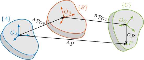
Furthermore, suppose the position vector of a point $P$ of the rigid body is given in the final location, that is ${}^CP$ is given, and the position of this point is to be found in the fixed frame $\{A\}$, that is ${}^AP$. Since the locations of the rigid body are known relative to each other, ${}^CP$ can be transformed to ${}^BP$ using ${}^B\bm{T}_C$ using ${}^BP = {}^B\bm{T}_C {}^CP$. Similarly, ${}^BP$ can be transformed into ${}^AP$ using ${}^AP = {}^A\bm{T}_B {}^BP$.
Combining the two relations, Equation eqref:eq:ustation_consecutive_transformations is obtained. This shows that combining multiple transformations is equivalent as to compute $4 \times 4$ matrix multiplications.
\begin{equation}\label{eq:ustation_consecutive_transformations} {}^AP = _brace{{}^A\bm{T}_B {}^B\bm{T}_C}_{{}^A\bm{T}_C} {}^CP
\end{equation}
Another key advantage of homogeneous transformation is the easy inverse transformation, which can be computed using Equation eqref:eq:ustation_inverse_homogeneous_transformation.
\begin{equation}\label{eq:ustation_inverse_homogeneous_transformation} {}^B\bm{T}_A = {}^A\bm{T}_B-1 = ≤ft[ \begin{array}{ccc|c} & & & \\ & {}^A\bm{R}_B^T & & -{}^A \bm{R}_B^T {}^AP_{O_B} \\ & & & \cr \hline 0 & 0 & 0 & 1 \\ \end{array} \right]
\end{equation}
Micro-Station Kinematics
<<ssec:ustation_kinematics>>
Each stage is described by two frames; one is attached to the fixed platform $\{A\}$ while the other is fixed to the mobile platform $\{B\}$. At "rest" position, the two have the same pose and coincide with the point of interest ($O_A = O_B$). An example of the tilt stage is shown in Figure ref:fig:ustation_stage_motion. The mobile frame of the translation stage is equal to the fixed frame of the tilt stage: $\{B_{D_y}\} = \{A_{R_y}\}$. Similarly, the mobile frame of the tilt stage is equal to the fixed frame of the spindle: $\{B_{R_y}\} = \{A_{R_z}\}$.

The motion induced by a positioning stage can be described by a homogeneous transformation matrix from frame $\{A\}$ to frame $\{B\}$ as explain in Section ref:ssec:ustation_kinematics. As any motion stage induces parasitic motion in all 6 DoF, the transformation matrix representing its induced motion can be written as in eqref:eq:ustation_translation_stage_errors.
\begin{equation}\label{eq:ustation_translation_stage_errors} {}^A\bm{T}_B(D_x, D_y, D_z, θ_x, θ_y, θ_z) = ≤ft[ \begin{array}{ccc|c} & & & D_x \\ & \bm{R}_x(\theta_x) \bm{R}_y(\theta_y) \bm{R}_z(\theta_z) & & D_y \\ & & & D_z \cr \hline 0 & 0 & 0 & 1 \end{array} \right]
\end{equation}
The homogeneous transformation matrix corresponding to the micro-station $\bm{T}_{\mu\text{-station}}$ is simply equal to the matrix multiplication of the homogeneous transformation matrices of the individual stages as shown in Equation eqref:eq:ustation_transformation_station.
\begin{equation}\label{eq:ustation_transformation_station} \bm{T}_{μ\text{-station}} = \bm{T}D_y ⋅ \bm{T}R_y ⋅ \bm{T}R_z ⋅ \bm{T}_{μ\text{-hexapod}}
\end{equation}
$\bm{T}_{\mu\text{-station}}$ represents the pose of the sample (supposed to be rigidly fixed on top of the positioning-hexapod) with respect to the granite.
If the transformation matrices of the individual stages are each representing a perfect motion (i.e. the stages are supposed to have no parasitic motion), $\bm{T}_{\mu\text{-station}}$ then represent the pose setpoint of the sample with respect to the granite. The transformation matrices for the translation stage, tilt stage, spindle, and positioning hexapod can be written as shown in Equation eqref:eq:ustation_transformation_matrices_stages.
\begin{equation}\label{eq:ustation_transformation_matrices_stages}
\begin{align} \bm{T}_{D_y} &= \begin{bmatrix} 1 & 0 & 0 & 0 \\ 0 & 1 & 0 & D_y \\ 0 & 0 & 1 & 0 \\ 0 & 0 & 0 & 1 \end{bmatrix} \quad \bm{T}_{\mu\text{-hexapod}} = \left[ \begin{array}{ccc|c} & & & D_{\mu x} \\ & \bm{R}_x(\theta_{\mu x}) \bm{R}_y(\theta_{\mu y}) \bm{R}_{z}(\theta_{\mu z}) & & D_{\mu y} \\ & & & D_{\mu z} \cr \hline 0 & 0 & 0 & 1 \end{array} \right] \\ \bm{T}_{R_z} &= \begin{bmatrix} \cos(\theta_z) & -\sin(\theta_z) & 0 & 0 \\ \sin(\theta_z) & \cos(\theta_z) & 0 & 0 \\ 0 & 0 & 1 & 0 \\ 0 & 0 & 0 & 1 \end{bmatrix} \quad \bm{T}_{R_y} = \begin{bmatrix} \cos(\theta_y) & 0 & \sin(\theta_y) & 0 \\ 0 & 1 & 0 & 0 \\ -\sin(\theta_y) & 0 & \cos(\theta_y) & 0 \\ 0 & 0 & 0 & 1 \end{bmatrix} \end{align}\end{equation}
Micro-Station Dynamics
<<sec:ustation_modeling>>
Introduction
In this section, the multi-body model of the micro-station is presented. Such model consists of several rigid bodies connected by springs and dampers. The inertia of the solid bodies and the stiffness properties of the guiding mechanisms were first estimated based on the CAD model and data-sheets (Section ref:ssec:ustation_model_simscape).
The obtained dynamics is then compared with the modal analysis performed on the micro-station (Section ref:ssec:ustation_model_comp_dynamics).
As the dynamics of the nano-hexapod is impacted by the micro-station compliance, the most important dynamical characteristic that should be well modeled is the overall compliance of the micro-station. To do so, the 6-DoF compliance of the micro-station is measured and then compared with the 6-DoF compliance extracted from the multi-body model (Section ref:ssec:ustation_model_compliance).
Multi-Body Model
<<ssec:ustation_model_simscape>>
By performing a modal analysis of the micro-station, it was verified that in the frequency range of interest, each stage behaved as a rigid body. This confirms that a multi-body model can be used to properly model the micro-station.
A multi-body model consists of several solid bodies connected by joints. Each solid body can be represented by its inertia properties (most of the time computed automatically from the 3D model and material density). Joints are used to impose kinematic constraints between solid bodies and to specify dynamical properties (i.e. spring stiffness and damping coefficient). External forces can be used to model disturbances, and "sensors" can be used to measure the relative pose between two defined frames.

Therefore, the micro-station is modeled by several solid bodies connected by joints. A typical stage (here the tilt-stage) is modeled as shown in Figure ref:fig:ustation_simscape_stage_example where two solid bodies (the fixed part and the mobile part) are connected by a 6-DoF joint. One DoF of the 6-DoF joint is "imposed" by a setpoint (i.e. modeled as infinitely stiff), while the other 5 are each modeled by a spring and damper. Additional forces can be used to model disturbances induced by the stage motion. The obtained 3D representation of the multi-body model is shown in Figure ref:fig:ustation_simscape_model.
The ground is modeled by a solid body connected to the "world frame" through a joint only allowing 3 translations. The granite was then connected to the ground using a 6-DoF joint. The translation stage is connected to the granite by a 6-DoF joint, but the $D_y$ motion is imposed. Similarly, the tilt-stage and the spindle are connected to the stage below using a 6-DoF joint, with 1 imposed DoF each time. Finally, the positioning hexapod has 6-DoF.
The total number of "free" degrees of freedom is 27, so the model has 54 states. The springs and dampers values were first estimated from the joint/stage specifications and were later fined-tuned based on the measurements. The spring values are summarized in Table ref:tab:ustation_6dof_stiffness_values.
| Stage | $D_x$ | $D_y$ | $D_z$ | $R_x$ | $R_y$ | $R_z$ |
|---|---|---|---|---|---|---|
| Granite | $5\,kN/\mu m$ | $5\,kN/\mu m$ | $5\,kN/\mu m$ | $25\,Nm/\mu\text{rad}$ | $25\,Nm/\mu\text{rad}$ | $10\,Nm/\mu\text{rad}$ |
| Translation | $200\,N/\mu m$ | - | $200\,N/\mu m$ | $60\,Nm/\mu\text{rad}$ | $90\,Nm/\mu\text{rad}$ | $60\,Nm/\mu\text{rad}$ |
| Tilt | $380\,N/\mu m$ | $400\,N/\mu m$ | $380\,N/\mu m$ | $120\,Nm/\mu\text{rad}$ | - | $120\,Nm/\mu\text{rad}$ |
| Spindle | $700\,N/\mu m$ | $700\,N/\mu m$ | $2\,kN/\mu m$ | $10\,Nm/\mu\text{rad}$ | $10\,Nm/\mu\text{rad}$ | - |
| Hexapod | $10\,N/\mu m$ | $10\,N/\mu m$ | $100\,N/\mu m$ | $1.5\,Nm/rad$ | $1.5\,Nm/rad$ | $0.27\,Nm/rad$ |
Comparison with the measured dynamics
<<ssec:ustation_model_comp_dynamics>>
The dynamics of the micro-station was measured by placing accelerometers on each stage and by impacting the translation stage with an instrumented hammer in three directions. The obtained FRFs were then projected at the CoM of each stage.
To gain a first insight into the accuracy of the obtained model, the FRFs from the hammer impacts to the acceleration of each stage were extracted from the multi-body model and compared with the measurements in Figure ref:fig:ustation_comp_com_response.
Even though there is some similarity between the model and the measurements (similar overall shapes and amplitudes), it is clear that the multi-body model does not accurately represent the complex micro-station dynamics. Tuning the numerous model parameters to better match the measurements is a highly non-linear optimization problem that is difficult to solve in practice.
Micro-station compliance
<<ssec:ustation_model_compliance>>
As discussed in the previous section, the dynamics of the micro-station is complex, and tuning the multi-body model parameters to obtain a perfect match is difficult.
When considering the NASS, the most important dynamical characteristics of the micro-station is its compliance, as it can affect the plant dynamics. Therefore, the adopted strategy is to accurately model the micro-station compliance.
The micro-station compliance was experimentally measured using the setup illustrated in Figure ref:fig:ustation_compliance_meas. Four 3-axis accelerometers were fixed to the micro-hexapod top platform. The micro-hexapod top platform was impacted at 10 different points. For each impact position, 10 impacts were performed to average and improve the data quality.
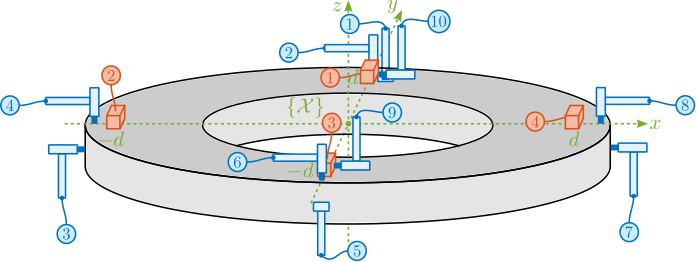
To convert the 12 acceleration signals $a_{\mathcal{L}} = [a_{1x}\ a_{1y}\ a_{1z}\ a_{2x}\ \dots\ a_{4z}]$ to the acceleration expressed in the frame $\{\mathcal{X}\}$ $a_{\mathcal{X}} = [a_{dx}\ a_{dy}\ a_{dz}\ a_{rx}\ a_{ry}\ a_{rz}]$, a Jacobian matrix $\bm{J}_a$ is written based on the positions and orientations of the accelerometers eqref:eq:ustation_compliance_acc_jacobian.
\begin{equation}\label{eq:ustation_compliance_acc_jacobian}
\bm{J}_a = \begin{bmatrix}
1 & 0 & 0 & 0 & 0 &-d
0 & 1 & 0 & 0 & 0 & 0
0 & 0 & 1 & d & 0 & 0
1 & 0 & 0 & 0 & 0 & 0
0 & 1 & 0 & 0 & 0 &-d
0 & 0 & 1 & 0 & d & 0
1 & 0 & 0 & 0 & 0 & d
0 & 1 & 0 & 0 & 0 & 0
0 & 0 & 1 &-d & 0 & 0
1 & 0 & 0 & 0 & 0 & 0
0 & 1 & 0 & 0 & 0 & d
0 & 0 & 1 & 0 &-d & 0
\end{bmatrix}
\end{equation}
Then, the acceleration in the cartesian frame can be computed using eqref:eq:ustation_compute_cart_acc.
\begin{equation}\label{eq:ustation_compute_cart_acc} a_{\mathcal{X}} = \bm{J}_a^† ⋅ a_{\mathcal{L}}
\end{equation}
Similar to what is done for the accelerometers, a Jacobian matrix $\bm{J}_F$ is computed eqref:eq:ustation_compliance_force_jacobian and used to convert the individual hammer forces $F_{\mathcal{L}}$ to force and torques $F_{\mathcal{X}}$ applied at the center of the micro-hexapod top plate (defined by frame $\{\mathcal{X}\}$ in Figure ref:fig:ustation_compliance_meas).
\begin{equation}\label{eq:ustation_compliance_force_jacobian}
\bm{J}_F = \begin{bmatrix}
0 & -1 & 0 & 0 & 0 & 0
0 & 0 & -1 & -d & 0 & 0
1 & 0 & 0 & 0 & 0 & 0
0 & 0 & -1 & 0 & -d & 0
0 & 1 & 0 & 0 & 0 & 0
0 & 0 & -1 & d & 0 & 0
-1 & 0 & 0 & 0 & 0 & 0
0 & 0 & -1 & 0 & d & 0
-1 & 0 & 0 & 0 & 0 & -d
-1 & 0 & 0 & 0 & 0 & d
\end{bmatrix}
\end{equation}
The equivalent forces and torques applied at center of $\{\mathcal{X}\}$ are then computed using eqref:eq:ustation_compute_cart_force.
\begin{equation}\label{eq:ustation_compute_cart_force} F_{\mathcal{X}} = \bm{J}_F^t ⋅ F_{\mathcal{L}}
\end{equation}
Using the two Jacobian matrices, the FRF from the 10 hammer impacts to the 12 accelerometer outputs can be converted to the FRF from 6 forces/torques applied at the origin of frame $\{\mathcal{X}\}$ to the 6 linear/angular accelerations of the top platform expressed with respect to $\{\mathcal{X}\}$. These FRFs were then used for comparison with the multi-body model.
The compliance of the micro-station multi-body model was extracted by computing the transfer function from forces/torques applied on the hexapod's top platform to the "absolute" motion of the top platform. These results are compared with the measurements in Figure ref:fig:ustation_frf_compliance_model. Considering the complexity of the micro-station compliance dynamics, the model compliance matches sufficiently well for the current application.
Estimation of Disturbances
<<sec:ustation_disturbances>>
Introduction
The goal of this section is to obtain a realistic representation of disturbances affecting the micro-station. These disturbance sources are then used during time domain simulations to accurately model the micro-station behavior. The focus on stochastic disturbances because, in principle, it is possible to calibrate the repeatable part of disturbances. Such disturbances include ground motions and vibrations induces by scanning the translation stage and the spindle.
In the multi-body model, stage vibrations are modeled as internal forces applied in the stage joint. In practice, disturbance forces cannot be directly measured. Instead, the vibrations of the micro-station's top platform induced by the disturbances were measured (Section ref:ssec:ustation_disturbances_meas).
To estimate the equivalent disturbance force that induces such vibration, the transfer functions from disturbance sources (i.e. forces applied in the stages' joint) to the displacements of the micro-station's top platform with respect to the granite are extracted from the multi-body model (Section ref:ssec:ustation_disturbances_sensitivity). Finally, the obtained disturbance sources are compared in Section ref:ssec:ustation_disturbances_results.
Disturbance measurements
<<ssec:ustation_disturbances_meas>>
Introduction
In this section, ground motion is directly measured using geophones. Vibrations induced by scanning the translation stage and the spindle are also measured using dedicated setups.
The tilt stage and the micro-hexapod also have positioning errors; however, they are not modeled here because these two stages are only used for pre-positioning and not for scanning. Therefore, from a control perspective, they are not important.
Ground Motion
The ground motion was measured by using a sensitive 3-axis geophone16 placed on the ground. The generated voltages were recorded with a high resolution DAC, and converted to displacement using the Geophone sensitivity transfer function. The obtained ground motion displacement is shown in Figure ref:fig:ustation_ground_disturbance.
\hfill
Ty Stage
To measure the positioning errors of the translation stage, the setup shown in Figure ref:fig:ustation_errors_ty_setup is used. A special optical element (called a "straightness interferometer"17) is fixed on top of the micro-station, while a laser source18 and a straightness reflector are fixed on the ground. A similar setup was used to measure the horizontal deviation (i.e. in the $x$ direction), as well as the pitch and yaw errors of the translation stage.
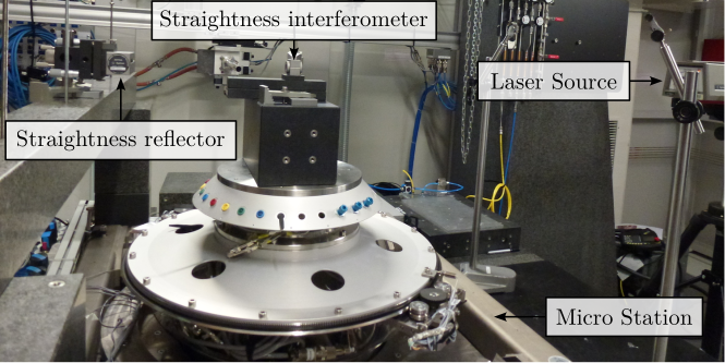
Six scans were performed between $-4.5\,mm$ and $4.5\,mm$. The results for each individual scan are shown in Figure ref:fig:ustation_errors_dy_vertical. The measurement axis may not be perfectly aligned with the translation stage axis; this, a linear fit is removed from the measurement. The remaining vertical displacement is shown in Figure ref:fig:ustation_errors_dy_vertical_remove_mean. A vertical error of $\pm300\,nm$ induced by the translation stage is expected. Similar result is obtained for the $x$ lateral direction.
Spindle
To measure the positioning errors induced by the Spindle, a "Spindle error analyzer"19 is used as shown in Figure ref:fig:ustation_rz_meas_lion_setup. A specific target is fixed on top of the micro-station, which consists of two sphere with 1 inch diameter precisely aligned with the spindle rotation axis. Five capacitive sensors20 are pointing at the two spheres, as shown in Figure ref:fig:ustation_rz_meas_lion_zoom. From the 5 measured displacements $[d_1,\,d_2,\,d_3,\,d_4,\,d_5]$, the translations and rotations $[D_x,\,D_y,\,D_z,\,R_x,\,R_y]$ of the target can be estimated.
A measurement was performed during a constant rotational velocity of the spindle of 60rpm and during 10 turns. The obtained results are shown in Figure ref:fig:ustation_errors_spindle. A large fraction of the radial (Figure ref:fig:ustation_errors_spindle_radial) and tilt (Figure ref:fig:ustation_errors_spindle_tilt) errors is linked to the fact that the two spheres are not perfectly aligned with the rotation axis of the Spindle. This is displayed by the dashed circle. After removing the best circular fit from the data, the vibrations induced by the Spindle may be viewed as stochastic disturbances. However, some misalignment between the "point-of-interest" of the sample and the rotation axis will be considered because the alignment is not perfect in practice. The vertical motion induced by scanning the spindle is in the order of $\pm 30\,nm$ (Figure ref:fig:ustation_errors_spindle_axial).
Sensitivity to disturbances
<<ssec:ustation_disturbances_sensitivity>>
To compute the disturbance source (i.e. forces) that induced the measured vibrations in Section ref:ssec:ustation_disturbances_meas, the transfer function from the disturbance sources to the stage vibration (i.e. the "sensitivity to disturbances") needs to be estimated. This is achieved using the multi-body model presented in Section ref:sec:ustation_modeling. The obtained transfer functions are shown in Figure ref:fig:ustation_model_sensitivity.
Obtained disturbance sources
<<ssec:ustation_disturbances_results>>
From the measured effect of disturbances in Section ref:ssec:ustation_disturbances_meas and the sensitivity to disturbances extracted from the multi-body model in Section ref:ssec:ustation_disturbances_sensitivity, the power spectral density of the disturbance sources (i.e. forces applied in the stage's joint) can be estimated. The obtained power spectral density of the disturbances are shown in Figure ref:fig:ustation_dist_sources.
The disturbances are characterized by their power spectral densities, as shown in Figure ref:fig:ustation_dist_sources. However, to perform time domain simulations, disturbances must be represented by a time domain signal. To generate stochastic time-domain signals with a specific power spectral densities, the discrete inverse Fourier transform is used, as explained in cite:&preumont94_random_vibrat_spect_analy chap. 12.11. Examples of the obtained time-domain disturbance signals are shown in Figure ref:fig:ustation_dist_sources_time.
Simulation of Scientific Experiments
<<sec:ustation_experiments>>
Introduction
To fully validate the micro-station multi-body model, two time-domain simulations corresponding to typical use cases were performed.
First, a tomography experiment (i.e. a constant Spindle rotation) was performed and was compared with experimental measurements (Section ref:sec:ustation_experiments_tomography). Second, a constant velocity scans with the translation stage was performed and also compared with the experimental data (Section ref:sec:ustation_experiments_ty_scans).
Tomography Experiment
<<sec:ustation_experiments_tomography>>
To simulate a tomography experiment, the setpoint of the Spindle is configured to perform a constant rotation with a rotational velocity of 60rpm. Both ground motion and spindle vibration disturbances were simulated based on what was computed in Section ref:sec:ustation_disturbances. A radial offset of $\approx 1\,\mu m$ between the "point-of-interest" and the spindle's rotation axis is introduced to represent what is experimentally observed. During the 10 second simulation (i.e. 10 spindle turns), the position of the "point-of-interest" with respect to the granite was recorded. Results are shown in Figure ref:fig:ustation_errors_model_spindle. A good correlation with the measurements is observed both for radial errors (Figure ref:fig:ustation_errors_model_spindle_radial) and axial errors (Figure ref:fig:ustation_errors_model_spindle_axial).
Raster Scans with the translation stage
<<sec:ustation_experiments_ty_scans>>
A second experiment was performed in which the translation stage was scanned at constant velocity. The translation stage setpoint is configured to have a "triangular" shape with stroke of $\pm 4.5\, mm$. Both ground motion and translation stage vibrations were included in the simulation. Similar to what was performed for the tomography simulation, the PoI position with respect to the granite was recorded and compared with the experimental measurements in Figure ref:fig:ustation_errors_model_dy_vertical. A similar error amplitude was observed, thus indicating that the multi-body model with the included disturbances accurately represented the micro-station behavior in typical scientific experiments.
Conclusion
<<sec:ustation_conclusion>>
In this study, a multi-body model of the micro-station was developed. It was difficult to match the measured dynamics obtained from the modal analysis of the micro-station. However, the most important dynamical characteristic to be modeled is the compliance, as it affects the dynamics of the NASS. After tuning the model parameters, a good match with the measured compliance was obtained (Figure ref:fig:ustation_frf_compliance_model).
The disturbances affecting the sample position should also be well modeled. After experimentally estimating the disturbances (Section ref:sec:ustation_disturbances), the multi-body model was finally validated by performing a tomography simulation (Figure ref:fig:ustation_errors_model_spindle) as well as a simulation in which the translation stage was scanned (Figure ref:fig:ustation_errors_model_dy_vertical).
Nano Hexapod - Multi Body Model
<<sec:nhexa>>
Introduction
Building upon the validated multi-body model of the micro-station presented in previous sections, this section focuses on the development and integration of an active vibration platform model.
A review of existing active vibration platforms is given in Section ref:sec:nhexa_platform_review, leading to the selection of the Stewart platform architecture. This parallel manipulator architecture, described in Section ref:sec:nhexa_stewart_platform, requires specialized analytical tools for kinematic analysis. However, the complexity of its dynamic behavior poses significant challenges for purely analytical approaches.
Consequently, a multi-body modeling approach was adopted (Section ref:sec:nhexa_model), facilitating seamless integration with the existing micro-station model.
The control of the Stewart platform introduces additional complexity due to its multi-input multi-output (MIMO) nature. Section ref:sec:nhexa_control explores how the High Authority Control/Low Authority Control (HAC-LAC) strategy, previously validated on the uniaxial model, can be adapted to address the coupled dynamics of the Stewart platform. This adaptation requires fundamental decisions regarding both the control architecture (centralized versus decentralized) and the control frame (Cartesian versus strut space). Through careful analysis of system interactions and plant characteristics in different frames, a control architecture combining decentralized Integral Force Feedback for active damping with a centralized high authority controller for positioning was developed, with both controllers implemented in the frame of the struts.
Active Vibration Platforms
<<sec:nhexa_platform_review>>
Introduction
The conceptual phase started with the use of simplified models, such as uniaxial and three-degree-of-freedom rotating systems. These models were chosen for their ease of analysis, and despite their simplicity, the principles derived from them usually apply to more complex systems. However, the development of the Nano Active Stabilization System (NASS) now requires the use of a more accurate model that will be integrated with the multi-body representation of the micro-station. To develop this model, the architecture of the active platform must first be determined.
The selection of an appropriate architecture begins with a review of existing positioning stages that incorporate active platforms similar to NASS (Section ref:ssec:nhexa_sample_stages). This review reveals two distinctive features of the NASS that set it apart from existing systems: the fact that the active platform is continuously rotating and its requirement to accommodate variable payload masses. In existing systems, the sample mass is typically negligible compared to the stage mass, whereas in NASS, the sample mass significantly influences the system's dynamic behavior.
These distinctive requirements drive the selection of the active platform architecture. In Section ref:ssec:nhexa_active_platforms, different active platform configurations, including serial and parallel configurations, are evaluated, ultimately leading to the choice of a Stewart platform architecture.
Sample Stages with Active Control
<<ssec:nhexa_sample_stages>>
The positioning of samples with respect to X-ray beam, that can be focused to sizes below 100 nanometers, presents significant challenges, because mechanical positioning systems are typically limited to micron-scale accuracy. To overcome this limitation, external metrology systems have been implemented to measure sample positions with nanometer accuracy, enabling real-time feedback control for sample stabilization.
A review of existing sample stages with active vibration control reveals various approaches to implementing such feedback systems. In many cases, sample position control is limited to translational degrees of freedom. At NSLS-II, for instance, a system capable of $100\,\mu m$ stroke has been developed for payloads up to 500g, utilizing interferometric measurements for position feedback (Figure ref:fig:nhexa_stages_nazaretski). Similarly, at the Sirius facility, a tripod configuration based on voice coil actuators has been implemented for XYZ position control, achieving feedback bandwidths of approximately 100 Hz (Figure ref:fig:nhexa_stages_sapoti).
The integration of $R_z$ rotational capability, which is necessary for tomography experiments, introduces additional complexity. At ESRF's ID16A beamline, a Stewart platform (whose architecture will be presented in Section ref:sec:nhexa_stewart_platform) using piezoelectric actuators has been positioned below the spindle (Figure ref:fig:nhexa_stages_villar). While this configuration enables the correction of spindle motion errors through 5-DoF control based on capacitive sensor measurements, the stroke is limited to $50\,\mu m$ due to the inherent constraints of piezoelectric actuators. In contrast, at PETRA III, an alternative approach places a XYZ-stacked stage above the spindle, offering $100\,\mu m$ stroke (Figure ref:fig:nhexa_stages_schroer). However, attempts to implement real-time feedback using YZ external metrology proved challenging, possibly due to the poor dynamical response of the serial stage configuration.
Table ref:tab:nhexa_sample_stages provides an overview of existing end-stations that incorporate feedback loops based on online metrology for sample positioning. Although direct performance comparisons between these systems are challenging due to their varying experimental requirements, scanning velocities, and specific use cases, several distinctive characteristics of the NASS can be identified.
| Stacked Stages | Specifications | Measured DoFs | Bandwidth | Reference |
|---|---|---|---|---|
| Sample | light | Interferometers | 3 PID, n/a | APS |
| XYZ stage (piezo) | $D_{xyz}: 0.05\,mm$ | $D_{xyz}$ | cite:&nazaretski15_pushin_limit | |
| Sample | light | Capacitive sensors | $\approx 10\,\text{Hz}$ | ESRF |
| Spindle | $R_z: \pm 90\,\text{deg}$ | $D_{xyz},\ R_{xy}$ | ID16a | |
| Hexapod (piezo) | $D_{xyz}: 0.05\,mm$ | cite:&villar18_nanop_esrf_id16a_nano_imagin_beaml | ||
| $R_{xy}: 500\,\mu\text{rad}$ | ||||
| Sample | light | Interferometers | n/a | PETRA III |
| XYZ stage (piezo) | $D_{xyz}: 0.1\,mm$ | $D_{yz}$ | P06 | |
| Spindle | $R_z: 180\,\text{deg}$ | cite:&schroer17_ptynam;&schropp20_ptynam | ||
| Sample | light | Interferometers | PID, n/a | PSI |
| Spindle | $R_z: \pm 182\,\text{deg}$ | $D_{yz},\ R_x$ | OMNY | |
| Tripod (piezo) | $D_{xyz}: 0.4\,mm$ | cite:&holler17_omny_pin_versat_sampl_holder;&holler18_omny_tomog_nano_cryo_stage | ||
| Sample | light | Interferometers | n/a | Soleil |
| (XY stage) | $D_{xyz},\ R_{xy}$ | Nanoprobe | ||
| Spindle | $R_z: 360\,\text{deg}$ | cite:&stankevic17_inter_charac_rotat_stages_x_ray_nanot;&engblom18_nanop_resul | ||
| XYZ linear motors | $D_{xyz}: 0.4\,mm$ | |||
| Sample | up to 0.5kg | Interferometers | n/a | NSLS |
| Spindle | $R_z: 360\,\text{deg}$ | $D_{xyz}$ | SRX | |
| XYZ stage (piezo) | $D_{xyz}: 0.1\,mm$ | cite:&nazaretski22_new_kirkp_baez_based_scann | ||
| Sample | up to 0.35kg | Interferometers | $\approx 100\,\text{Hz}$ | Diamond, I14 |
| Parallel XYZ VC | $D_{xyz}: 3\,mm$ | $D_{xyz}$ | cite:&kelly22_delta_robot_long_travel_nano | |
| Sample | light | Capacitive sensors | $\approx 100\,\text{Hz}$ | LNLS |
| Parallel XYZ VC | $D_{xyz}: 3\,mm$ | and interferometers | CARNAUBA | |
| (Spindle) | $R_z: \pm 110 \,\text{deg}$ | $D_{xyz}$ | cite:&geraldes23_sapot_carnaub_sirius_lnls | |
| Sample | up to 50kg | $D_{xyz},\ R_{xy}$ | ESRF | |
| Active Platform | ID31 | |||
| (Micro-Hexapod) | cite:&dehaeze18_sampl_stabil_for_tomog_exper;&dehaeze21_mechat_approac_devel_nano_activ_stabil_system | |||
| Spindle | $R_z: 360\,\text{deg}$ | |||
| Tilt-Stage | $R_y: \pm 3\,\text{deg}$ | |||
| Translation Stage | $D_y: \pm 10\,mm$ |
The first key distinction of the NASS is in the continuous rotation of the active vibration platform. This feature introduces significant complexity through gyroscopic effects and real-time changes in the platform orientation, which substantially impact both the system's kinematics and dynamics. In addition, NASS implements a unique Long-Stroke/Short-Stroke architecture. In conventional systems, active platforms typically correct spindle positioning errors - for example, unwanted translations or tilts that occur during rotation, whereas the intended rotational motion ($R_z$) is performed by the spindle itself and is not corrected. The NASS, however, faces a more complex task: it must compensate for positioning errors of the translation and tilt stages in real time during their operation, including corrections along their primary axes of motion. For instance, when the translation stage moves along Y, the active platform must not only correct for unwanted motions in other directions but also correct the position along Y, which necessitate some synchronization between the control of the long stroke stages and the control of the active platform.
The second major distinguishing feature of the NASS is its capability to handle payload masses up to 50 kg, exceeding typical capacities in the literature by two orders of magnitude. This substantial increase in payload mass fundamentally alters the system's dynamic behavior, as the sample mass significantly influences the overall system dynamics, in contrast to conventional systems where sample masses are negligible relative to the stage mass. This characteristic introduces significant control challenges, as the feedback system must remain stable and maintain performance across a wide range of payload masses (from a few kilograms to 50 kg), requiring robust control strategies to handle such large plant variations.
The NASS also distinguishes itself through its high mobility and versatility, which are achieved through the use of multiple stacked stages (translation stage, tilt stage, spindle, positioning hexapod) that enable a wide range of experimental configurations. The resulting mechanical structure exhibits complex dynamics with multiple resonance modes in the low frequency range. This dynamic complexity poses significant challenges for the design and control of the active platform.
The primary control requirements focus on $[D_y,\ D_z,\ R_y]$ motions; however, the continuous rotation of the active platform requires the control of $[D_x,\ D_y,\ D_z,\ R_x,\ R_y]$ in the active platform's reference frame.
Active Vibration Platform
<<ssec:nhexa_active_platforms>>
The choice of the active platform architecture for the NASS requires careful consideration of several critical specifications. The platform must provide control over five degrees of freedom ($D_x$, $D_y$, $D_z$, $R_x$, and $R_y$), with strokes exceeding $100\,\mu m$ to correct for micro-station positioning errors, while fitting within a cylindrical envelope of 300 mm diameter and 95 mm height. It must accommodate payloads up to 50 kg while maintaining high dynamical performance. For light samples, the typical design strategy of maximizing actuator stiffness works well because resonance frequencies in the kilohertz range can be achieved, enabling control bandwidths up to 100 Hz. However, achieving such resonance frequencies with a 50 kg payload would require unrealistic stiffness values of approximately $2000\,N/\mu m$. This limitation necessitates alternative control approaches, and the High Authority Control/Low Authority Control (HAC-LAC) strategy is proposed to address this challenge. To this purpose, the design includes force sensors for active damping. Compliant mechanisms must also be used to eliminate friction and backlash, which would otherwise compromise the nano-positioning capabilities.
Two primary categories of positioning platform architectures are considered: serial and parallel mechanisms. Serial robots, characterized by open-loop kinematic chains, typically dedicate one actuator per degree of freedom as shown in Figure ref:fig:nhexa_serial_architecture_kenton. While offering large workspaces and high maneuverability, serial mechanisms suffer from several inherent limitations. These include low structural stiffness, cumulative positioning errors along the kinematic chain, high mass-to-payload ratios due to actuator placement, and limited payload capacity cite:&taghirad13_paral. These limitations generally make serial architectures unsuitable for nano-positioning applications, except when handling very light samples, as was used in cite:&nazaretski15_pushin_limit and shown in Figure ref:fig:nhexa_stages_nazaretski.
In contrast, parallel mechanisms, which connect the mobile platform to the fixed base through multiple parallel struts, offer several advantages for precision positioning. Their closed-loop kinematic structure provides inherently higher structural stiffness, as the platform is simultaneously supported by multiple struts cite:&taghirad13_paral. Although parallel mechanisms typically exhibit limited workspace compared to serial architectures, this limitation is not critical for NASS given its modest stroke requirements. Numerous parallel kinematic architectures have been developed cite:dong07_desig_precis_compl_paral_posit to address various positioning requirements, with designs varying based on the desired degrees of freedom and specific application constraints. Furthermore, hybrid architectures combining both serial and parallel elements have been proposed cite:&shen19_dynam_analy_flexur_nanop_stage, as illustrated in Figure ref:fig:nhexa_serial_parallel_examples, offering potential compromises between the advantages of both approaches.
After evaluating the different options, the Stewart platform architecture was selected for several reasons. In addition to providing control over all required degrees of freedom, its compact design and predictable dynamic characteristics make it particularly suitable for nano-positioning when combined with flexible joints. Stewart platforms have been implemented in a wide variety of configurations, as illustrated in Figure ref:fig:nhexa_stewart_examples, which shows two distinct implementations: one utilizing piezoelectric actuators for nano-positioning applications, and another based on voice coil actuators for vibration isolation. These examples demonstrate the architecture's versatility in terms of geometry, actuator selection, and scale, all of which can be optimized for specific applications. Furthermore, the successful implementation of Integral Force Feedback (IFF) control on Stewart platforms has been well documented cite:&abu02_stiff_soft_stewar_platf_activ;&hanieh03_activ_stewar;&preumont07_six_axis_singl_stage_activ, and the extensive body of research on this architecture enables thorough optimization specifically for the NASS.
The Stewart platform
<<sec:nhexa_stewart_platform>>
Introduction
The Stewart platform, first introduced by Stewart in 1965 cite:&stewart65_platf_with_six_degrees_freed for flight simulation applications, represents a significant milestone in parallel manipulator design. This mechanical architecture has evolved far beyond its original purpose, and has been applied across diverse field, from precision positioning systems to robotic surgery. The fundamental design consists of two platforms connected by six adjustable struts in parallel, creating a fully parallel manipulator capable of six degrees of freedom motion.
Unlike serial manipulators, in which errors worsen through the kinematic chain, parallel architectures distribute loads across multiple actuators, leading to enhanced mechanical stiffness and improved positioning accuracy. This parallel configuration also results in superior dynamic performance because the actuators directly contribute to the platform's motion without intermediate linkages. These characteristics make the Stewart platforms particularly valuable in applications requiring high precision and stiffness.
For the NASS application, the Stewart platform architecture offers three key advantages. First, as a fully parallel manipulator, all the motion errors of the micro-station can be compensated through the coordinated action of the six actuators. Second, its compact design compared to serial manipulators makes it ideal for integration on top micro-station where only $95\,mm$ of height is available. Third, the good dynamical properties should enable high-bandwidth positioning control.
While Stewart platforms excel in precision and stiffness, they typically exhibit a relatively limited workspace compared to serial manipulators. However, this limitation is not significant for the NASS application, as the required motion range corresponds to the positioning errors of the micro-station, which are in the order of $10\,\mu m$.
This section provides a comprehensive analysis of the Stewart platform's properties, focusing on aspects crucial for precision positioning applications. The analysis encompasses the platform's kinematic relationships (Section ref:ssec:nhexa_stewart_platform_kinematics), the use of the Jacobian matrix (Section ref:ssec:nhexa_stewart_platform_jacobian), static behavior (Section ref:ssec:nhexa_stewart_platform_static), and dynamic characteristics (Section ref:ssec:nhexa_stewart_platform_dynamics). These theoretical foundations form the basis for subsequent design decisions and control strategies, which will be elaborated in later sections.
Mechanical Architecture
<<ssec:nhexa_stewart_platform_architecture>>
The Stewart platform consists of two rigid platforms connected by six parallel struts (Figure ref:fig:nhexa_stewart_architecture). Each strut is modelled with an active prismatic joint that allows for controlled length variation, with its ends attached to the fixed and mobile platforms through joints. The typical configuration consists of a universal joint at one end and a spherical joint at the other, providing the necessary degrees of freedom21.
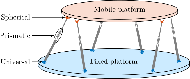
To facilitate the rigorous analysis of the Stewart platform, four reference frames were defined:
- The fixed base frame $\{F\}$, which is located at the center of the base platform's bottom surface, serves as the mounting reference for the support structure.
- The mobile frame $\{M\}$, which is located at the center of the top platform's upper platform, provides a reference for payload mounting.
- The point-of-interest frame $\{A\}$, fixed to the base but positioned at the workspace center.
- The moving point-of-interest frame $\{B\}$, attached to the mobile platform coincides with frame $\{A\}$ in the home position.
Frames $\{F\}$ and $\{M\}$ serve primarily to define the joint locations. In contrast, frames $\{A\}$ and $\{B\}$ are used to describe the relative motion of the two platforms through the position vector ${}^A\bm{P}_B$ of frame $\{B\}$ expressed in frame $\{A\}$ and the rotation matrix ${}^A\bm{R}_B$ expressing the orientation of $\{B\}$ with respect to $\{A\}$. For the nano-hexapod, frames $\{A\}$ and $\{B\}$ are chosen to be located at the theoretical focus point of the X-ray light which is $150\,mm$ above the top platform, i.e. above $\{M\}$.
The location of the joints and the orientation and length of the struts are crucial for subsequent kinematic, static, and dynamic analyses of the Stewart platform. The center of rotation for the joint fixed to the base is noted $\bm{a}_i$, while $\bm{b}_i$ is used for the top platform joints. The struts' orientations are represented by the unit vectors $\hat{\bm{s}}_i$ and their lengths are represented by the scalars $l_i$. This is summarized in Figure ref:fig:nhexa_stewart_notations.
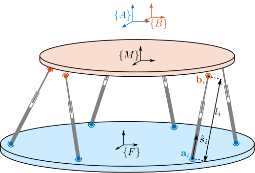
Kinematic Analysis
<<ssec:nhexa_stewart_platform_kinematics>>
Loop Closure
The foundation of the kinematic analysis lies in the geometric constraints imposed by each strut, which can be expressed using loop closure equations. For each strut $i$ (illustrated in Figure ref:fig:nhexa_stewart_loop_closure), the loop closure equation eqref:eq:nhexa_loop_closure can be written.
\begin{equation}\label{eq:nhexa_loop_closure} {}^A\bm{P}_B = {}^A\bm{a}_i + l_i{}^A\hat{\bm{s}}_i - _brace{{}^B\bm{b}_i}_{{}^A\bm{R}_B {}^B\bm{b}_i} \quad \text{for } i=1 \text{ to } 6
\end{equation}
This equation links the pose22 variables ${}^A\bm{P}$ and ${}^A\bm{R}_B$, the position vectors describing the known geometry of the base and the moving platform, $\bm{a}_i$ and $\bm{b}_i$, and the strut vector $l_i {}^A\hat{\bm{s}}_i$:
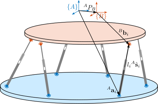
Inverse Kinematics
The inverse kinematic problem involves determining the required strut lengths $\bm{\mathcal{L}} = \left[ l_1, l_2, \ldots, l_6 \right]^T$ for a desired platform pose $\bm{\mathcal{X}}$ (i.e. position ${}^A\bm{P}$ and orientation ${}^A\bm{R}_B$). This problem can be solved analytically using the loop closure equations eqref:eq:nhexa_loop_closure. The obtained strut lengths are given by eqref:eq:nhexa_inverse_kinematics.
\begin{equation}\label{eq:nhexa_inverse_kinematics} l_i = \sqrt{{}^A\bm{P}^T {}^A\bm{P} + {}^B\bm{b}_i^T {}^B\bm{b}_i + {}^A\bm{a}_i^T {}^A\bm{a}_i - 2 {}^A\bm{P}^T {}^A\bm{a}_i + 2 {}^A\bm{P}^T ≤ft[{}^A\bm{R}_B {}^B\bm{b}_i\right] - 2 ≤ft[{}^A\bm{R}_B {}^B\bm{b}_i\right]^T {}^A\bm{a}_i}
\end{equation}
If the position and orientation of the platform lie in the feasible workspace, the solution is unique. While configurations outside this workspace yield complex numbers, this only becomes relevant for large displacements that far exceed the nano-hexapod's operating range.
Forward Kinematics
The forward kinematic problem seeks to determine the platform pose $\bm{\mathcal{X}}$ given a set of strut lengths $\bm{\mathcal{L}}$. Unlike inverse kinematics, this presents a significant challenge because it requires solving a system of nonlinear equations. Although various numerical methods exist for solving this problem, they can be computationally intensive and may not guarantee convergence to the correct solution.
For the nano-hexapod application, where displacements are typically small, an approximate solution based on linearization around the operating point provides a practical alternative. This approximation, which is developed in subsequent sections through the Jacobian matrix analysis, is particularly useful for real-time control applications.
The Jacobian Matrix
<<ssec:nhexa_stewart_platform_jacobian>>
Introduction
The Jacobian matrix plays a central role in analyzing the Stewart platform's behavior, providing a linear mapping between the platform and actuator velocities. While the previously derived kinematic relationships are essential for position analysis, the Jacobian enables velocity analysis and forms the foundation for both static and dynamic studies.
Jacobian Computation
As discussed in Section ref:ssec:nhexa_stewart_platform_kinematics, the strut lengths $\bm{\mathcal{L}}$ and the platform pose $\bm{\mathcal{X}}$ are related through a system of nonlinear algebraic equations representing the kinematic constraints imposed by the struts.
By taking the time derivative of the position loop close eqref:eq:nhexa_loop_closure, equation eqref:eq:nhexa_loop_closure_velocity is obtained23.
\begin{equation}\label{eq:nhexa_loop_closure_velocity} {}^A\bm{v}_p + {}^A \dot{\bm{R}}_B {}^B\bm{b}_i + {}^A\bm{R}_B _brace{{}^B\dot{\bm{b}_i}}=0 = \dot{l}_i {}^A\hat{\bm{s}}_i + l_i {}^A\dot{\hat{\bm{s}}}_i + _brace{{}^A\dot{\bm{a}}_i}=0
\end{equation}
Moreover, we have:
- ${}^A\dot{\bm{R}}_B {}^B\bm{b}_i = {}^A\bm{\omega} \times {}^A\bm{R}_B {}^B\bm{b}_i = {}^A\bm{\omega} \times {}^A\bm{b}_i$ in which ${}^A\bm{\omega}$ denotes the angular velocity of the moving platform expressed in the fixed frame $\{\bm{A}\}$.
- $l_i {}^A\dot{\hat{\bm{s}}}_i = l_i \left( {}^A\bm{\omega}_i \times \hat{\bm{s}}_i \right)$ in which ${}^A\bm{\omega}_i$ is the angular velocity of strut $i$ express in fixed frame $\{\bm{A}\}$.
By multiplying both sides by ${}^A\hat{\bm{s}}_i$, eqref:eq:nhexa_loop_closure_velocity_bis is obtained.
\begin{equation}\label{eq:nhexa_loop_closure_velocity_bis} {}^A\hat{\bm{s}}_i {}^A\bm{v}_p + _brace{{}^A\hat{\bm{s}}_i ({}^A\bm{ω} × {}^A\bm{b}_i)}_{=({}^A\bm{b}_i × {}^A\hat{\bm{s}}_i) {}^A\bm{ω}} = \dot{l}_i + _brace{{}^A\hat{s}_i l_i ≤ft( {}^A\bm{ω}_i × {}^A\hat{\bm{s}}_i \right)}=0
\end{equation}
Equation eqref:eq:nhexa_loop_closure_velocity_bis can be rearranged in matrix form to obtain eqref:eq:nhexa_jacobian_velocities, with $\dot{\bm{\mathcal{L}}} = [ \dot{l}_1 \ \dots \ \dot{l}_6 ]^T$ the vector of strut velocities, and $\dot{\bm{\mathcal{X}}} = [{}^A\bm{v}_p ,\ {}^A\bm{\omega}]^T$ the vector of platform velocity and angular velocity.
\begin{equation}\label{eq:nhexa_jacobian_velocities} \boxed{\dot{\bm{\mathcal{L}}} = \bm{J} \dot{\bm{\mathcal{X}}}}
\end{equation}
The matrix $\bm{J}$ is called the Jacobian matrix and is defined by eqref:eq:nhexa_jacobian, with ${}^A\hat{\bm{s}}_i$ the orientation of the struts expressed in $\{A\}$ and ${}^A\bm{b}_i$ the position of the joints with respect to $O_B$ and express in $\{A\}$.
\begin{equation}\label{eq:nhexa_jacobian}
\bm{J} = \begin{bmatrix}
{{}^A\hat{\bm{s}}_1}^T & ({}^A\bm{b}_1 × {}^A\hat{\bm{s}}_1)^T
{{}^A\hat{\bm{s}}_2}^T & ({}^A\bm{b}_2 × {}^A\hat{\bm{s}}_2)^T
{{}^A\hat{\bm{s}}_3}^T & ({}^A\bm{b}_3 × {}^A\hat{\bm{s}}_3)^T
{{}^A\hat{\bm{s}}_4}^T & ({}^A\bm{b}_4 × {}^A\hat{\bm{s}}_4)^T
{{}^A\hat{\bm{s}}_5}^T & ({}^A\bm{b}_5 × {}^A\hat{\bm{s}}_5)^T
{{}^A\hat{\bm{s}}_6}^T & ({}^A\bm{b}_6 × {}^A\hat{\bm{s}}_6)^T
\end{bmatrix}
\end{equation}
Therefore, the Jacobian matrix $\bm{J}$ links the rate of change of the strut length to the velocity and angular velocity of the top platform with respect to the fixed base through a set of linear equations. However, $\bm{J}$ needs to be recomputed for every Stewart platform pose because it depends on the actual pose of the manipulator.
Approximate solution to the Forward and Inverse Kinematic problems
For small displacements $\delta \bm{\mathcal{X}} = [\delta x, \delta y, \delta z, \delta \theta_x, \delta \theta_y, \delta \theta_z ]^T$ around an operating point $\bm{\mathcal{X}}_0$ (for which the Jacobian was computed), the associated joint displacement $\delta\bm{\mathcal{L}} = [\delta l_1,\,\delta l_2,\,\delta l_3,\,\delta l_4,\,\delta l_5,\,\delta l_6]^T$ can be computed using the Jacobian eqref:eq:nhexa_inverse_kinematics_approximate.
\begin{equation}\label{eq:nhexa_inverse_kinematics_approximate} \boxed{δ\bm{\mathcal{L}} = \bm{J} δ\bm{\mathcal{X}}}
\end{equation}
Similarly, for small joint displacements $\delta\bm{\mathcal{L}}$, it is possible to find the induced small displacement of the mobile platform eqref:eq:nhexa_forward_kinematics_approximate.
\begin{equation}\label{eq:nhexa_forward_kinematics_approximate} \boxed{δ\bm{\mathcal{X}} = \bm{J}-1 δ\bm{\mathcal{L}}}
\end{equation}
These two relations solve the forward and inverse kinematic problems for small displacement in a approximate way. While this approximation offers limited value for inverse kinematics, which can be solved analytically, it proves particularly useful for the forward kinematic problem where exact analytical solutions are difficult to obtain.
Range validity of the approximate inverse kinematics
The accuracy of the Jacobian-based forward kinematics solution was estimated by a simple analysis. For a series of platform positions, the exact strut lengths are computed using the analytical inverse kinematics equation eqref:eq:nhexa_inverse_kinematics. These strut lengths are then used with the Jacobian to estimate the platform pose eqref:eq:nhexa_forward_kinematics_approximate, from which the error between the estimated and true poses can be calculated, both in terms of position $\epsilon_D$ and orientation $\epsilon_R$.
For motion strokes from $1\,\mu m$ to $10\,mm$, the errors are estimated for all direction of motion, and the worst case errors are shown in Figure ref:fig:nhexa_forward_kinematics_approximate_errors. The results demonstrate that for displacements up to approximately $1\,\%$ of the hexapod's size (which corresponds to $100\,\mu m$ as the size of the Stewart platform is here $\approx 100\,mm$), the Jacobian approximation provides excellent accuracy.
Since the maximum required stroke of the nano-hexapod ($\approx 100\,\mu m$) is three orders of magnitude smaller than its overall size ($\approx 100\,mm$), the Jacobian matrix can be considered constant throughout the workspace. It can be computed once at the rest position and used for both forward and inverse kinematics with high accuracy.
Static Forces
The static force analysis of the Stewart platform can be performed using the principle of virtual work. This principle states that for a system in static equilibrium, the total virtual work of all forces acting on the system must be zero for any virtual displacement compatible with the system's constraints.
Let $\bm{f} = [f_1, f_2, \cdots, f_6]^T$ represent the vector of actuator forces applied in each strut, and $\bm{\mathcal{F}} = [\bm{F}, \bm{n}]^T$ denote the external wrench (combined force $\bm{F}$ and torque $\bm{n}$) acting on the mobile platform at point $\bm{O}_B$. The virtual work $\delta W$ consists of two contributions:
- The work performed by the actuator forces through virtual strut displacements $\delta \bm{\mathcal{L}}$: $\bm{f}^T \delta \bm{\mathcal{L}}$
- The work performed by the external wrench through virtual platform displacements $\delta \bm{\mathcal{X}}$: $-\bm{\mathcal{F}}^T \delta \bm{\mathcal{X}}$
Thus, the principle of virtual work can be expressed as:
\begin{equation} \delta W = \bm{f}^T \delta \bm{\mathcal{L}} - \bm{\mathcal{F}}^T \delta \bm{\mathcal{X}} = 0 \end{equation}Using the Jacobian relationship that links virtual displacements eqref:eq:nhexa_inverse_kinematics_approximate, this equation becomes:
\begin{equation} \left( \bm{f}^T \bm{J} - \bm{\mathcal{F}}^T \right) \delta \bm{\mathcal{X}} = 0 \end{equation}Because this equation must hold for any virtual displacement $\delta \bm{\mathcal{X}}$, the force mapping relationships eqref:eq:nhexa_jacobian_forces can be derived.
\begin{equation}\label{eq:nhexa_jacobian_forces} \bm{f}^T \bm{J} - \bm{\mathcal{F}}^T = 0 \quad ⇒ \quad \boxed{\bm{\mathcal{F}} = \bm{J}^T \bm{f}} \quad \text{and} \quad \boxed{\bm{f} = \bm{J}-T \bm{\mathcal{F}}}
\end{equation}
These equations establish that the transpose of the Jacobian matrix maps actuator forces to platform forces and torques, while its inverse transpose maps platform forces and torques to required actuator forces.
Static Analysis
<<ssec:nhexa_stewart_platform_static>>
The static stiffness characteristics of the Stewart platform play a crucial role in its performance, particularly for precision positioning applications. These characteristics are fundamentally determined by both the actuator properties and the platform geometry.
Starting from the individual actuators, the relationship between applied force $f_i$ and resulting displacement $\delta l_i$ for each strut $i$ is characterized by its stiffness $k_i$:
\begin{equation} f_i = k_i \delta l_i, \quad i = 1,\ \dots,\ 6 \end{equation}These individual relationships can be combined into a matrix form using the diagonal stiffness matrix $\bm{\mathcal{K}}$:
\begin{equation} \bm{f} = \bm{\mathcal{K}} \cdot \delta \bm{\mathcal{L}}, \quad \bm{\mathcal{K}} = \text{diag}\left[ k_1,\ \dots,\ k_6 \right] \end{equation}By applying the force mapping relationships eqref:eq:nhexa_jacobian_forces derived in the previous section and the Jacobian relationship for small displacements eqref:eq:nhexa_forward_kinematics_approximate, the relationship between applied wrench $\bm{\mathcal{F}}$ and resulting platform displacement $\delta \bm{\mathcal{X}}$ is obtained eqref:eq:nhexa_stiffness_matrix.
\begin{equation}\label{eq:nhexa_stiffness_matrix} \bm{\mathcal{F}} = _brace{\bm{J}^T \bm{\mathcal{K}} \bm{J}}_{\bm{K}} ⋅ δ \bm{\mathcal{X}}
\end{equation} where $\bm{K} = \bm{J}^T \bm{\mathcal{K}} \bm{J}$ is identified as the platform stiffness matrix.
The inverse relationship is given by the compliance matrix $\bm{C}$:
\begin{equation} \delta \bm{\mathcal{X}} = \underbrace{(\bm{J}^T \bm{\mathcal{K}} \bm{J})^{-1}}_{\bm{C}} \bm{\mathcal{F}} \end{equation}These relationships reveal that the overall platform stiffness and compliance characteristics are determined by two factors:
- The individual actuator stiffnesses represented by $\bm{\mathcal{K}}$
- The geometric configuration embodied in the Jacobian matrix $\bm{J}$
This geometric dependency means that the platform's stiffness varies throughout its workspace, as the Jacobian matrix changes with the platform's position and orientation. For the NASS application, where the workspace is small compared to the platform dimensions, these variations can be considered negligible. However, the initial geometric configuration significantly affects the overall stiffness characteristics. The relationship between maximum stroke and stiffness presents another important design consideration. As both parameters are influenced by the geometric configuration, their optimization involves inherent trade-offs that must be carefully balanced based on the application requirements. The optimization of this configuration to achieve the desired stiffness while having sufficient stroke will be addressed during the detailed design phase.
Dynamical Analysis
<<ssec:nhexa_stewart_platform_dynamics>>
For initial analysis, a simplified representation of the system has been developed. This model assumes perfectly rigid bodies for both the platform and base, connected by massless struts through ideal joints that exhibit neither friction nor compliance.
Under these assumptions, the system dynamics can be expressed in Cartesian space as:
\begin{equation} \bm{M} s^2 \bm{\mathcal{X}} = \Sigma \bm{\mathcal{F}} \end{equation}where $\bm{M}$ represents the platform mass matrix, $\bm{\mathcal{X}}$ the platform pose, and $\Sigma \bm{\mathcal{F}}$ the sum of forces acting on the platform.
The primary forces acting on the system are actuator forces $\bm{f}$, elastic forces due to strut stiffness $-\bm{\mathcal{K}} \bm{\mathcal{L}}$ and damping forces in the struts $\bm{\mathcal{C}} \dot{\bm{\mathcal{L}}}$.
\begin{equation} \Sigma \bm{\mathcal{F}} = \bm{J}^T (\bm{f} - \bm{\mathcal{K}} \bm{\mathcal{L}} - s \bm{\mathcal{C}} \bm{\mathcal{L}}), \quad \bm{\mathcal{K}} = \text{diag}(k_1\,\dots\,k_6),\ \bm{\mathcal{C}} = \text{diag}(c_1\,\dots\,c_6) \end{equation}Combining these forces and using eqref:eq:nhexa_forward_kinematics_approximate yields the complete dynamic equation eqref:eq:nhexa_dynamical_equations.
\begin{equation}\label{eq:nhexa_dynamical_equations} \bm{M} s^2 \bm{\mathcal{X}} = \bm{\mathcal{F}} - \bm{J}^T \bm{\mathcal{K}} \bm{J} \bm{\mathcal{X}} - \bm{J}^T \bm{\mathcal{C}} \bm{J} s \bm{\mathcal{X}}
\end{equation}
The transfer function matrix in the Cartesian frame becomes eqref:eq:nhexa_transfer_function_cart.
\begin{equation}\label{eq:nhexa_transfer_function_cart} \frac{{\mathcal{X}}}{\bm{\mathcal{F}}}(s) = ( \bm{M} s^2 + \bm{J}T \bm{\mathcal{C}} \bm{J} s + \bm{J}T \bm{\mathcal{K}} \bm{J} )-1
\end{equation}
Through coordinate transformation using the Jacobian matrix, the dynamics in the actuator space is obtained eqref:eq:nhexa_transfer_function_struts.
\begin{equation}\label{eq:nhexa_transfer_function_struts} \frac{\bm{\mathcal{L}}}{\bm{f}}(s) = ( \bm{J}-T \bm{M} \bm{J}-1 s^2 + \bm{\mathcal{C}} + \bm{\mathcal{K}} )-1
\end{equation}
Although this simplified model provides useful insights, real Stewart platforms exhibit more complex behaviors. Several factors can significantly increase the model complexity, such as:
- Strut dynamics, including mass distribution and internal resonances cite:&afzali-far16_inert_matrix_hexap_strut_joint_space;&chen04_decoup_contr_flexur_joint_hexap
- Joint compliance and friction effects cite:&mcinroy00_desig_contr_flexur_joint_hexap;&mcinroy02_model_desig_flexur_joint_stewar
- Supporting structure dynamics and payload dynamics, which are both very critical for NASS
These additional effects render analytical modeling impractical for complete system analysis.
Conclusion
The fundamental characteristics of the Stewart platform have been analyzed in this chapter. Essential kinematic relationships were developed through loop closure equations, from which both exact and approximate solutions for the inverse and forward kinematic problems were derived. The Jacobian matrix was established as a central mathematical tool through which crucial insights into velocity relationships, static force transmission, and dynamic behavior of the platform were obtained.
For the NASS application, where displacements are typically limited to the micrometer range, the accuracy of linearized models using a constant Jacobian matrix has been demonstrated, by which both analysis and control can be significantly simplified. However, additional complexities such as strut masses, joint compliance, and supporting structure dynamics must be considered in the full dynamic behavior. This will be performed in the next section using a multi-body model.
All these characteristics (maneuverability, stiffness, dynamics, etc.) are fundamentally determined by the platform's geometry. While a reasonable geometric configuration will be used to validate the NASS during the conceptual phase, the optimization of these geometric parameters will be explored during the detailed design phase.
Multi-Body Model
<<sec:nhexa_model>>
Introduction
The dynamic modeling of Stewart platforms has traditionally relied on analytical approaches. However, these analytical models become increasingly complex when the dynamical behaviors of struts and joints must be captured. To overcome these limitations, a flexible multi-body approach was developed that can be readily integrated into the broader NASS model. Through this multi-body modeling approach, each component model (including joints, actuators, and sensors) can be progressively refined.
The analysis is structured as follows. First, the multi-body model is developed, and the geometric parameters, inertial properties, and actuator characteristics are established (Section ref:ssec:nhexa_model_def). The model is then validated through comparison with the analytical equations in a simplified configuration (Section ref:ssec:nhexa_model_validation). Finally, the validated model is employed to analyze the nano-hexapod dynamics, from which insights for the control system design are derived (Section ref:ssec:nhexa_model_dynamics).
Model Definition
<<ssec:nhexa_model_def>>
Geometry
The Stewart platform's geometry is defined by two principal coordinate frames (Figure ref:fig:nhexa_stewart_model_def): a fixed base frame $\{F\}$ and a moving platform frame $\{M\}$. The joints connecting the actuators to these frames are located at positions ${}^F\bm{a}_i$ and ${}^M\bm{b}_i$ respectively. The point of interest, denoted by frame $\{A\}$, is situated $150\,mm$ above the moving platform frame $\{M\}$.
The geometric parameters of the nano-hexapod are summarized in Table ref:tab:nhexa_stewart_model_geometry. These parameters define the positions of all connection points in their respective coordinate frames. From these parameters, key kinematic properties can be derived: the strut orientations $\hat{\bm{s}}_i$, strut lengths $l_i$, and the system's Jacobian matrix $\bm{J}$.
\hfill
| $\bm{x}$ | $\bm{y}$ | $\bm{z}$ | |
|---|---|---|---|
| ${}^M\bm{O}_B$ | $0$ | $0$ | $150$ |
| ${}^F\bm{O}_M$ | $0$ | $0$ | $95$ |
| ${}^F\bm{a}_1$ | $-92$ | $-77$ | $20$ |
| ${}^F\bm{a}_2$ | $92$ | $-77$ | $20$ |
| ${}^F\bm{a}_3$ | $113$ | $-41$ | $20$ |
| ${}^F\bm{a}_4$ | $21$ | $118$ | $20$ |
| ${}^F\bm{a}_5$ | $-21$ | $118$ | $20$ |
| ${}^F\bm{a}_6$ | $-113$ | $-41$ | $20$ |
| ${}^M\bm{b}_1$ | $-28$ | $-106$ | $-20$ |
| ${}^M\bm{b}_2$ | $28$ | $-106$ | $-20$ |
| ${}^M\bm{b}_3$ | $106$ | $28$ | $-20$ |
| ${}^M\bm{b}_4$ | $78$ | $78$ | $-20$ |
| ${}^M\bm{b}_5$ | $-78$ | $78$ | $-20$ |
| ${}^M\bm{b}_6$ | $-106$ | $28$ | $-20$ |
Inertia of Plates
The fixed base and moving platform were modeled as solid cylindrical bodies. The base platform was characterized by a radius of $120\,mm$ and thickness of $15\,mm$, matching the dimensions of the micro-hexapod's top platform. The moving platform was similarly modeled with a radius of $110\,mm$ and thickness of $15\,mm$. Both platforms were assigned a mass of $5\,kg$.
Joints
The platform's joints play a crucial role in its dynamic behavior. At both the upper and lower connection points, various degrees of freedom can be modeled, including universal joints, spherical joints, and configurations with additional axial and lateral stiffness components. For each degree of freedom, stiffness characteristics can be incorporated into the model.
In the conceptual design phase, a simplified joint configuration is employed: the bottom joints are modeled as two-degree-of-freedom universal joints, while the top joints are represented as three-degree-of-freedom spherical joints. These joints are considered massless and exhibit no stiffness along their degrees of freedom.
Actuators
The actuator model comprises several key elements (Figure ref:fig:nhexa_actuator_model). At its core, each actuator is modeled as a prismatic joint with internal stiffness $k_a$ and damping $c_a$, driven by a force source $f$. Similarly to what was found using the rotating 3-DoF model, a parallel stiffness $k_p$ is added in parallel with the force sensor to ensure stability when considering spindle rotation effects.
Each actuator is equipped with two sensors: a force sensor providing measurements $f_n$ and a relative motion sensor that measures the strut length $l_i$. The actuator parameters used in the conceptual phase are listed in Table ref:tab:nhexa_actuator_parameters.
This modular approach to actuator modeling allows for future refinements as the design evolves, enabling the incorporation of additional dynamic effects or sensor characteristics as needed.
\hfill
| Value | |
|---|---|
| $k_a$ | $1\,N/\mu m$ |
| $c_a$ | $50\,N/(m/s)$ |
| $k_p$ | $0.05\,N/\mu m$ |
Validation of the multi-body model
<<ssec:nhexa_model_validation>>
The developed multi-body model of the Stewart platform is represented schematically in Figure ref:fig:nhexa_stewart_model_input_outputs, highlighting the key inputs and outputs: actuator forces $\bm{f}$, force sensor measurements $\bm{f}_n$, and relative displacement measurements $\bm{\mathcal{L}}$. The frames $\{F\}$ and $\{M\}$ serve as interfaces for integration with other elements in the multi-body system. A three-dimensional visualization of the model is presented in Figure ref:fig:nhexa_simscape_screenshot.
\hfill
The validation of the multi-body model was performed using the simplest Stewart platform configuration, enabling direct comparison with the analytical transfer functions derived in Section ref:ssec:nhexa_stewart_platform_dynamics. This configuration consists of massless universal joints at the base, massless spherical joints at the top platform, and massless struts with stiffness $k_a = 1\,\text{N}/\mu\text{m}$ and damping $c_a = 10\,\text{N}/({\text{m}/\text{s}})$. The geometric parameters remain as specified in Table ref:tab:nhexa_actuator_parameters.
While the moving platform itself is considered massless, a $10\,\text{kg}$ cylindrical payload is mounted on top with a radius of $r = 110\,mm$ and a height $h = 300\,mm$.
For the analytical model, the stiffness, damping, and mass matrices are defined in eqref:eq:nhexa_analytical_matrices.
\begin{subequations}\label{eq:nhexa_analytical_matrices}
\begin{align} \bm{\mathcal{K}} &= \text{diag}(k_a,\ k_a,\ k_a,\ k_a,\ k_a,\ k_a) \\ \bm{\mathcal{C}} &= \text{diag}(c_a,\ c_a,\ c_a,\ c_a,\ c_a,\ c_a) \\ \bm{M} &= \text{diag}\left(m,\ m,\ m,\ \frac{1}{12}m(3r^2 + h^2),\ \frac{1}{12}m(3r^2 + h^2),\ \frac{1}{2}mr^2\right) \end{align}\end{subequations}
The transfer functions from the actuator forces to the strut displacements are computed using these matrices according to equation eqref:eq:nhexa_transfer_function_struts. These analytical transfer functions are then compared with those extracted from the multi-body model. The developed multi-body model yields a state-space representation with 12 states, corresponding to the six degrees of freedom of the moving platform.
Figure ref:fig:nhexa_comp_multi_body_analytical presents a comparison between the analytical and multi-body transfer functions, specifically showing the response from the first actuator force to all six strut displacements. The close agreement between both approaches across the frequency spectrum validates the multi-body model's accuracy in capturing the system's dynamic behavior.
Nano Hexapod Dynamics
<<ssec:nhexa_model_dynamics>>
Following the validation of the multi-body model, a detailed analysis of the nano-hexapod dynamics was performed. The model parameters were set according to the specifications outlined in Section ref:ssec:nhexa_model_def, with a payload mass of $10\,kg$. The transfer functions from actuator forces $\bm{f}$ to both strut displacements $\bm{\mathcal{L}}$ and force measurements $\bm{f}_n$ were derived from the multi-body model.
The transfer functions relating actuator forces to strut displacements are presented in Figure ref:fig:nhexa_multi_body_plant_dL. Due to the system's symmetrical design and identical strut configurations, all diagonal terms (transfer functions from force $f_i$ to displacement $l_i$ of the same strut) exhibit identical behavior. While the system has six degrees of freedom, only four distinct resonance frequencies were observed in the frequency response. This reduction from six to four observable modes is attributed to the system's symmetry, where two pairs of resonances occur at identical frequencies.
The system's behavior can be characterized in three frequency regions. At low frequencies, well below the first resonance, the plant demonstrates good decoupling between actuators, with the response dominated by the strut stiffness: $\bm{G}(j\omega) \xrightarrow[\omega \to 0]{} \bm{\mathcal{K}}^{-1}$. In the mid-frequency range, the system exhibits coupled dynamics through its resonant modes, reflecting the complex interactions between the platform's degrees of freedom. At high frequencies, above the highest resonance, the response is governed by the payload's inertia mapped to the strut coordinates: $\bm{G}(j\omega) \xrightarrow[\omega \to \infty]{} \bm{J} \bm{M}^{-T} \bm{J}^T \frac{-1}{\omega^2}$
The force sensor transfer functions, shown in Figure ref:fig:nhexa_multi_body_plant_fm, display characteristics typical of collocated actuator-sensor pairs. Each actuator's transfer function to its associated force sensor exhibits alternating complex conjugate poles and zeros. The inclusion of parallel stiffness introduces an additional complex conjugate zero at low frequency, which was previously observed in the three-degree-of-freedom rotating model.
Conclusion
The multi-body modeling approach presented in this section provides a comprehensive framework for analyzing the dynamics of the nano-hexapod system. Through comparison with analytical solutions in a simplified configuration, the model's accuracy has been validated, demonstrating its ability to capture the essential dynamic behavior of the Stewart platform.
A key advantage of this modeling approach lies in its flexibility for future refinements. While the current implementation employs idealized joints for the conceptual design phase, the framework readily accommodates the incorporation of joint stiffness and other non-ideal effects. The joint stiffness, which is known to impact the performance of decentralized IFF control strategy cite:&preumont07_six_axis_singl_stage_activ, will be studied and optimized during the detailed design phase. The validated multi-body model will serve as a valuable tool for predicting system behavior and evaluating control performance throughout the design process.
Control of Stewart Platforms
<<sec:nhexa_control>>
Introduction
The control of Stewart platforms presents distinct challenges compared to the uniaxial model due to their multi-input multi-output nature. Although the uniaxial model demonstrated the effectiveness of the HAC-LAC strategy, its extension to Stewart platforms requires careful considerations discussed in this section.
First, the distinction between centralized and decentralized control approaches is discussed in Section ref:ssec:nhexa_control_centralized_decentralized. The impact of the control space selection - either Cartesian or strut space - is then analyzed in Section ref:ssec:nhexa_control_space, highlighting the trade-offs between direction-specific tuning and implementation simplicity.
Building on these analyses, a decentralized active damping strategy using Integral Force Feedback is developed in Section ref:ssec:nhexa_control_iff, followed by the implementation of a centralized High Authority Control for positioning in Section ref:ssec:nhexa_control_hac_lac. This architecture, while simple, will be used to demonstrate the feasibility of the NASS concept and will provide a foundation for more sophisticated control strategies to be developed during the detailed design phase.
Centralized and Decentralized Control
<<ssec:nhexa_control_centralized_decentralized>>
In the control of MIMO systems, and more specifically of Stewart platforms, a fundamental architectural decision lies in the choice between centralized and decentralized control strategies.
In decentralized control, each actuator operates based on feedback from its associated sensor only, creating independent control loops, as illustrated in Figure ref:fig:nhexa_stewart_decentralized_control. While mechanical coupling between the struts exists, control decisions are made locally, with each controller processing information from a single sensor-actuator pair. This approach offers simplicity in implementation and reduces computational requirements.
Conversely, centralized control uses information from all sensors to determine the control action of each actuator. This strategy potentially enables better performance by explicitly accounting for the mechanical coupling between the struts, though at the cost of increased complexity in both design and implementation.
The choice between these approaches depends significantly on the degree of interaction between the different control channels, and also on the available sensors and actuators. For instance, when using external metrology systems that measure the platform's global position, centralized control becomes necessary because each sensor measurement depends on all actuator inputs.
In the context of the nano-hexapod, two distinct control strategies were examined during the conceptual phase:
- Decentralized Integral Force Feedback (IFF), which utilizes collocated force sensors to implement independent control loops for each strut (Section ref:ssec:nhexa_control_iff)
- High-Authority Control (HAC), which employs a centralized approach to achieve precise positioning based on external metrology measurements (Section ref:ssec:nhexa_control_hac_lac)
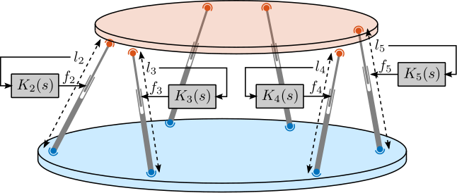
Choice of the Control Space
<<ssec:nhexa_control_space>>
When controlling a Stewart platform using external metrology that measures the pose of frame $\{B\}$ with respect to $\{A\}$, denoted as $\bm{\mathcal{X}}$, the control architecture can be implemented in either Cartesian or strut space. This choice affects both the control design and the obtained performance.
Control in the Strut space
In this approach, as illustrated in Figure ref:fig:nhexa_control_strut, the control is performed in the space of the struts. The Jacobian matrix is used to solve the inverse kinematics in real-time by mapping position errors from Cartesian space $\bm{\epsilon}_{\mathcal{X}}$ to strut space $\bm{\epsilon}_{\mathcal{L}}$. A diagonal controller then processes these strut-space errors to generate force commands for each actuator.
The main advantage of this approach emerges from the plant characteristics in the strut space, as shown in Figure ref:fig:nhexa_plant_frame_struts. The diagonal terms of the plant (transfer functions from force to displacement of the same strut, as measured by the external metrology) are identical due to the system's symmetry. This simplifies the control design because only one controller needs to be tuned. Furthermore, at low frequencies, the plant exhibits good decoupling between the struts, allowing for effective independent control of each axis.
\begin{tikzpicture}
  % Blocs
  \node[block={2.0cm}{2.0cm}] (P) {Plant};
  \coordinate[] (inputF) at ($(P.south west)!0.5!(P.north west)$);
  \coordinate[] (outputX) at ($(P.south east)!0.5!(P.north east)$);

  \node[block={2.0cm}{2.0cm}, left=0.8 of inputF] (K) {\begin{matrix}K_1 & & 0 \\ & \ddots & \\ 0 & & K_6\end{matrix}};
  \node[block, left=0.8 of K] (J) {$\bm{J}$};
  \node[addb={+}{}{}{}{-}, left=0.8 of J] (subr) {};
  % \node[block, align=center, left=0.6 of subr] (J) {Inverse\\Kinematics};

  % Connections and labels
  \draw[->] (outputX) -- ++(0.8, 0);
  \draw[->] ($(outputX) + (0.3, 0)$)node[branch]{} node[above]{$\bm{\mathcal{X}}$} -- ++(0, -1.2) -| (subr.south);
  \draw[->] (subr.east) -- node[midway, above]{$\bm{\epsilon}_{\mathcal{X}}$} (J.west);
  \draw[->] (J.east) -- node[midway, above]{$\bm{\epsilon}_{\mathcal{L}}$} (K.west);
  \draw[->] (K.east) -- node[midway, above]{$\bm{f}$} (inputF);

  \draw[<-] (subr.west)node[above left]{$\bm{r}_{\mathcal{X}}$} -- ++(-0.8, 0);
\end{tikzpicture}\begin{tikzpicture}
% Blocs
\node[block={2.0cm}{2.0cm}] (P) {Plant};
\coordinate[] (inputF) at ($(P.south west)!0.5!(P.north west)$);
\coordinate[] (outputX) at ($(P.south east)!0.5!(P.north east)$);
\node[block, left=0.8 of inputF] (J) {$\bm{J}^{-T}$};
\node[block={2.0cm}{2.0cm}, left=0.8 of J] (K) {\begin{matrix}K_{D_x} & & 0 \\ & \ddots & \\ 0 & & K_{R_z}\end{matrix}};
\node[addb={+}{}{}{}{-}, left=0.8 of K] (subr) {};
% Connections and labels
\draw[->] (outputX) -- ++(0.8, 0);
\draw[->] ($(outputX) + (0.3, 0)$)node[branch]{} node[above]{$\bm{\mathcal{X}}$} -- ++(0, -1.2) -| (subr.south);
\draw[->] (subr.east) -- node[midway, above]{$\bm{\epsilon}_{\mathcal{X}}$} (K.west);
\draw[->] (K.east) -- node[midway, above]{$\bm{\mathcal{F}}$} (J.west);
\draw[->] (J.east) -- node[midway, above]{$\bm{f}$} (inputF.west);
\draw[<-] (subr.west)node[above left]{$\bm{r}_{\mathcal{X}}$} -- ++(-0.8, 0);
\end{tikzpicture}Control in Cartesian Space
Alternatively, control can be implemented directly in Cartesian space, as illustrated in Figure ref:fig:nhexa_control_cartesian. Here, the controller processes Cartesian errors $\bm{\epsilon}_{\mathcal{X}}$ to generate forces and torques $\bm{\mathcal{F}}$, which are then mapped to actuator forces using the transpose of the inverse Jacobian matrix eqref:eq:nhexa_jacobian_forces.
The plant behavior in Cartesian space, illustrated in Figure ref:fig:nhexa_plant_frame_cartesian, reveals interesting characteristics. Some degrees of freedom, particularly the vertical translation and rotation about the vertical axis, exhibit simpler second-order dynamics. A key advantage of this approach is that the control performance can be tuned individually for each direction. This is particularly valuable when performance requirements differ between degrees of freedom - for instance, when higher positioning accuracy is required vertically than horizontally, or when certain rotational degrees of freedom can tolerate larger errors than others.
However, significant coupling exists between certain degrees of freedom, particularly between rotations and translations (e.g., $\epsilon_{R_x}/\mathcal{F}_y$ or $\epsilon_{D_y}/\bm\mathcal{M}_x$).
For the conceptual validation of the nano-hexapod, control in the strut space was selected due to its simpler implementation and the beneficial decoupling properties observed at low frequencies. More sophisticated control strategies will be explored during the detailed design phase.
Active Damping with Decentralized IFF
<<ssec:nhexa_control_iff>>
The decentralized Integral Force Feedback (IFF) control strategy is implemented using independent control loops for each strut, similarly to what is shown in Figure ref:fig:nhexa_stewart_decentralized_control, but using force sensors instead of relative motion sensors.
The corresponding block diagram of the control loop is shown in Figure ref:fig:nhexa_decentralized_iff_schematic, in which the controller $\bm{K}_{\text{IFF}}(s)$ is a diagonal matrix, where each diagonal element is a pure integrator eqref:eq:nhexa_kiff.
\begin{tikzpicture}
  % Blocs
  \node[block={2.0cm}{2.0cm}] (P) {Plant};
  \coordinate[] (input)   at ($(P.south west)!0.5!(P.north west)$);
  \coordinate[] (outputH) at ($(P.south east)!0.2!(P.north east)$);
  \coordinate[] (outputL) at ($(P.south east)!0.8!(P.north east)$);

  \node[block, above=0.2 of P] (Klac) {$\bm{K}_\text{IFF}$};
  \node[addb, left=0.8 of input] (addF) {};

  % Connections and labels
  \draw[->] (outputL) -- ++(0.7, 0) coordinate(eastlac) |- (Klac.east);
  \node[above right] at (outputL){$\bm{f}_n$};
  \draw[->] (Klac.west) -| (addF.north);
  \draw[->] (addF.east) -- (input) node[above left]{$\bm{f}$};

  \draw[->] (outputH) -- ++(1.7, 0) node[above left]{$\bm{\mathcal{L}}$};
  \draw[<-] (addF.west) -- ++(-0.8, 0) node[above right]{$\bm{f}^{\prime}$};

  \begin{scope}[on background layer]
    \node[fit={(Klac.north-|eastlac) (addF.west|-P.south)}, fill=black!20!white, draw, dashed, inner sep=8pt] (Pi) {};
    \node[anchor={north west}] at (Pi.north west){\footnotesize{Damped Plant}};
  \end{scope}
\end{tikzpicture}\begin{equation}\label{eq:nhexa_kiff} \bm{K}_{\text{IFF}}(s) = g ⋅ \begin{bmatrix} K_{\text{IFF}}(s) & & 0 \\ & \ddots & \\ 0 & & K_{\text{IFF}}(s) \end{bmatrix}, \quad K_{\text{IFF}}(s) = \frac{1}{s}
\end{equation}
In this section, the stiffness in parallel with the force sensor was omitted since the Stewart platform is not subjected to rotation. The effect of this parallel stiffness is examined in the next section when the platform is integrated into the complete NASS.
Root Locus analysis, shown in Figure ref:fig:nhexa_decentralized_iff_root_locus, reveals the evolution of the closed-loop poles as the controller gain $g$ varies from $0$ to $\infty$. A key characteristic of force feedback control with collocated sensor-actuator pairs is observed: all closed-loop poles are bounded to the left-half plane, indicating guaranteed stability cite:&preumont08_trans_zeros_struc_contr_with. This property is particularly valuable because the coupling is very large around resonance frequencies, enabling control of modes that would be difficult to include within the bandwidth using position feedback alone.
The bode plot of an individual loop gain (i.e. the loop gain of $K_{\text{IFF}}(s) \cdot \frac{f_{ni}}{f_i}(s)$), presented in Figure ref:fig:nhexa_decentralized_iff_loop_gain, exhibits the typical characteristics of integral force feedback of having a phase bounded between $-90^o$ and $+90^o$. The loop-gain is high around the resonance frequencies, indicating that the decentralized IFF provides significant control authority over these modes. This high gain, combined with the bounded phase, enables effective damping of the resonant modes while maintaining stability.
MIMO High-Authority Control - Low-Authority Control
<<ssec:nhexa_control_hac_lac>>
The design of the High Authority Control positioning loop is now examined. The complete HAC-IFF control architecture is illustrated in Figure ref:fig:nhexa_hac_iff_schematic, where the reference signal $\bm{r}_{\mathcal{X}}$ represents the desired pose, and $\bm{\mathcal{X}}$ is the measured pose by the external metrology system.
Following the analysis from Section ref:ssec:nhexa_control_space, the control is implemented in the strut space. The Jacobian matrix $\bm{J}^{-1}$ performs (approximate) real-time approximate inverse kinematics to map position errors from Cartesian space $\bm{\epsilon}_{\mathcal{X}}$ to strut space $\bm{\epsilon}_{\mathcal{L}}$. A diagonal High Authority Controller $\bm{K}_{\text{HAC}}$ then processes these errors in the frame of the struts.
\begin{tikzpicture}
  % Blocs
  \node[block={2.0cm}{2.0cm}] (P) {Plant};
  \coordinate[] (input)   at ($(P.south west)!0.5!(P.north west)$);
  \coordinate[] (outputH) at ($(P.south east)!0.2!(P.north east)$);
  \coordinate[] (outputL) at ($(P.south east)!0.8!(P.north east)$);

  \node[block, above=0.2 of P] (Klac) {$\bm{K}_\text{IFF}$};
  \node[addb, left=0.8 of input] (addF) {};

  \node[block, left=0.8 of addF] (Khac) {$\bm{K}_\text{HAC}$};
  \node[block, left=0.8 of Khac] (inverseK) {$\bm{J}$};

  \node[addb={+}{}{}{}{-}, left=0.8 of inverseK] (subL) {};

  % Connections and labels
  \draw[->] (outputL) -- ++(0.7, 0) coordinate(eastlac) |- (Klac.east);
  \node[above right] at (outputL){$\bm{f}_n$};
  \draw[->] (Klac.west) -| (addF.north);
  \draw[->] (addF.east) -- (input) node[above left]{$\bm{f}$};

  \draw[->] (outputH) -- ++(1.7, 0) node[above left]{$\bm{\mathcal{X}}$};
  \draw[->] (Khac.east) node[above right]{$\bm{f}^{\prime}$} -- (addF.west);

  \draw[->] ($(outputH) + (1.2, 0)$)node[branch]{} |- ($(subL.south)+(0, -1.2)$) -- (subL.south);
  \draw[->] (subL.east) -- (inverseK.west) node[above left]{$\bm{\epsilon}_\mathcal{X}$};
  \draw[->] (inverseK.east) -- (Khac.west) node[above left]{$\bm{\epsilon}_\mathcal{L}$};

  \draw[<-] (subL.west) -- ++(-0.8, 0) node[above right]{$\bm{r}_\mathcal{X}$};

  \begin{scope}[on background layer]
    \node[fit={(Klac.north-|eastlac) (addF.west|-P.south)}, fill=black!20!white, draw, dashed, inner sep=8pt] (Pi) {};
    \node[anchor={north west}] at (Pi.north west){\footnotesize{Damped Plant}};
  \end{scope}
\end{tikzpicture}The effect of decentralized IFF on the plant dynamics can be observed by comparing two sets of transfer functions. Figure ref:fig:nhexa_decentralized_hac_iff_plant_undamped shows the original transfer functions from actuator forces $\bm{f}$ to strut errors $\bm{\epsilon}_{\mathcal{L}}$, which are characterized by pronounced resonant peaks. When the decentralized IFF is implemented, the transfer functions from modified inputs $\bm{f}^{\prime}$ to strut errors $\bm{\epsilon}_{\mathcal{L}}$ exhibit significantly attenuated resonances (Figure ref:fig:nhexa_decentralized_hac_iff_plant_damped). This damping of structural resonances serves two purposes: it reduces vibrations near resonances and simplifies the design of the high authority controller by providing simpler plant dynamics.
Based upon the damped plant dynamics shown in Figure ref:fig:nhexa_decentralized_hac_iff_plant_damped, a high authority controller was designed with the structure given in eqref:eq:nhexa_khac. The controller combines three elements: an integrator providing high gain at low frequencies, a lead compensator improving stability margins, and a low-pass filter for robustness against unmodeled high-frequency dynamics. The loop gain of an individual control channel is shown in Figure ref:fig:nhexa_decentralized_hac_iff_loop_gain.
\begin{equation}\label{eq:nhexa_khac} \bm{K}_{\text{HAC}}(s) = \begin{bmatrix} K_{\text{HAC}}(s) & & 0 \\ & \ddots & \\ 0 & & K_{\text{HAC}}(s) \end{bmatrix}, \quad K_{\text{HAC}}(s) = g_0 ⋅ _brace{\frac{ω_c}{s}}_{\text{int}} ⋅ _brace{\frac{1}{\sqrt{α}}\frac{1 + \frac{s}{ω_c/\sqrt{α}}}{1 + \frac{s}{ω_c\sqrt{α}}}}_{\text{lead}} ⋅ _brace{\frac{1}{1 + \frac{s}{ω_0}}}_{\text{LPF}}
\end{equation}
The stability of the MIMO feedback loop is analyzed through the characteristic loci method. Such characteristic loci represent the eigenvalues of the loop gain matrix $\bm{G}(j\omega)\bm{K}(j\omega)$ plotted in the complex plane as the frequency varies from $0$ to $\infty$. For MIMO systems, this method generalizes the classical Nyquist stability criterion: with the open-loop system being stable, the closed-loop system is stable if none of the characteristic loci encircle the -1 point cite:&skogestad07_multiv_feedb_contr. As shown in Figure ref:fig:nhexa_decentralized_hac_iff_root_locus, all loci remain to the right of the $-1$ point, validating the stability of the closed-loop system. Additionally, the distance of the loci from the $-1$ point provides information about stability margins of the coupled system.
Conclusion
The control architecture developed for the uniaxial and the rotating models was adapted for the Stewart platform.
Two fundamental choices were first addressed: the selection between centralized and decentralized approaches and the choice of control space. While control in Cartesian space enables direction-specific performance tuning, implementation in strut space was selected for the conceptual design phase due to two key advantages: good decoupling at low frequencies and identical diagonal terms in the plant transfer functions, allowing a single controller design to be replicated across all struts.
The HAC-LAC strategy was then implemented. The inner loop implements decentralized Integral Force Feedback for active damping. The collocated nature of the force sensors ensures stability despite strong coupling between struts at resonance frequencies, enabling effective damping of structural modes. The outer loop implements High Authority Control, enabling precise positioning of the mobile platform.
Conclusion
<<sec:nhexa_conclusion>>
After evaluating various architectures, the Stewart platform was selected for the active platform. The parallel kinematic structure offers superior dynamical characteristics, and its compact design satisfies the strict space constraints of the NASS. The extensive literature on Stewart platforms, including kinematic analysis, dynamic modeling and control, provides a robust theoretical foundation for this choice.
A configurable multi-body model of the Stewart platform was developed and validated against analytical equations. The modular nature of the model allows for progressive refinement of individual components (plates, joints and actuators) and geometry, making it a valuable tool throughout the development process. The validated model will be integrated into the broader multi-body representation of the micro-station, enabling comprehensive analysis of the complete NASS.
The use of this model extends beyond the current conceptual phase. It will serve as a crucial tool during the detailed design phase, where it will be used to optimize the design and guide the development of sophisticated control strategies. Furthermore, during the experimental phase, it will provide a theoretical framework for comparing and understanding measured dynamics.
The control aspects of the Stewart platform were addressed with particular attention to the challenges posed by its multi-input multi-output nature. Although the coupled dynamics of the system suggest the potential benefit of advanced control strategies, a simplified architecture was proposed for the validation of the NASS concept. This approach combines decentralized Integral Force Feedback for active damping with High Authority Control for positioning, which was implemented in the strut space to leverage the natural decoupling observed at low frequencies.
This study establishes the theoretical framework necessary for the subsequent development and validation of the NASS.
Validation of the Concept
<<sec:nass>>
Introduction
The previous chapters have established crucial foundational elements for the development of the Nano Active Stabilization System (NASS). The uniaxial model study demonstrated that very stiff nano-hexapod configurations should be avoided due to their high coupling with the micro-station dynamics. A rotating three-degree-of-freedom model revealed that soft nano-hexapod designs prove unsuitable due to gyroscopic effect induced by the spindle rotation. To further improve the model accuracy, a multi-body model of the micro-station was developed, which was carefully tuned using experimental modal analysis. Furthermore, a multi-body model of the nano-hexapod was created, that can then be seamlessly integrated with the micro-station model, as illustrated in Figure ref:fig:nass_simscape_model.
Building upon these foundations, this chapter presents the validation of the NASS concept. The investigation begins with the previously established nano-hexapod model with actuator stiffness $k_a = 1\,N/\mu m$. A thorough examination of the control kinematics is presented in Section ref:sec:nass_kinematics, detailing how both external metrology and nano-hexapod internal sensors are used in the control architecture. The control strategy is then implemented in two steps: first, the decentralized IFF is used for active damping (Section ref:sec:nass_active_damping), then a High Authority Control is develop to stabilize the sample's position in a large bandwidth (Section ref:sec:nass_hac).
The robustness of the proposed control scheme was evaluated under various operational conditions. Particular attention was paid to system performance under changing payload masses and varying spindle rotational velocities.
This chapter concludes the conceptual design phase, with the simulation of tomography experiments providing strong evidence for the viability of the proposed NASS architecture.
Control Kinematics
<<sec:nass_kinematics>>
Introduction
Figure ref:fig:nass_concept_schematic presents a schematic overview of the NASS. This section focuses on the components of the "Instrumentation and Real-Time Control" block.
As established in the previous section on Stewart platforms, the proposed control strategy combines Decentralized Integral Force Feedback with a High Authority Controller performed in the frame of the struts.
For the Nano Active Stabilization System, computing the positioning errors in the frame of the struts involves three key steps. First, desired sample pose with respect to a fixed reference frame is computed using the micro-station kinematics as detailed in Section ref:ssec:nass_ustation_kinematics. This fixed frame is located at the X-ray beam focal point, as it is where the point of interest needs to be positioned. Second, it measures the actual sample pose relative to the same fix frame, described in Section ref:ssec:nass_sample_pose_error. Finally, it determines the sample pose error and maps these errors to the nano-hexapod struts, as explained in Section ref:ssec:nass_error_struts.
The complete control architecture is described in Section ref:ssec:nass_control_architecture.
Micro Station Kinematics
<<ssec:nass_ustation_kinematics>>
The micro-station kinematics enables the computation of the desired sample pose from the reference signals of each micro-station stage. These reference signals consist of the desired lateral position $r_{D_y}$, tilt angle $r_{R_y}$, and spindle angle $r_{R_z}$. The micro-hexapod pose is defined by six parameters: three translations ($r_{D_{\mu x}}$, $r_{D_{\mu y}}$, $r_{D_{\mu z}}$) and three rotations ($r_{\theta_{\mu x}}$, $r_{\theta_{\mu y}}$, $r_{\theta_{\mu z}}$).
Using these reference signals, the desired sample position relative to the fixed frame is expressed through the homogeneous transformation matrix $\bm{T}_{\mu\text{-station}}$, as defined in equation eqref:eq:nass_sample_ref.
\begin{equation}\label{eq:nass_sample_ref} \bm{T}_{μ\text{-station}} = \bm{T}D_y ⋅ \bm{T}R_y ⋅ \bm{T}R_z ⋅ \bm{T}_{μ\text{-hexapod}}
\end{equation}
\begin{equation}\label{eq:nass_ustation_matrices}
\begin{align} \bm{T}_{D_y} &= \begin{bmatrix} 1 & 0 & 0 & 0 \\ 0 & 1 & 0 & r_{D_y} \\ 0 & 0 & 1 & 0 \\ 0 & 0 & 0 & 1 \end{bmatrix} \quad \bm{T}_{\mu\text{-hexapod}} = \left[ \begin{array}{ccc|c} & & & r_{D_{\mu x}} \\ & \bm{R}_x(r_{\theta_{\mu x}}) \bm{R}_y(r_{\theta_{\mu y}}) \bm{R}_{z}(r_{\theta_{\mu z}}) & & r_{D_{\mu y}} \\ & & & r_{D_{\mu z}} \cr \hline 0 & 0 & 0 & 1 \end{array} \right] \\ \bm{T}_{R_z} &= \begin{bmatrix} \cos(r_{R_z}) & -\sin(r_{R_z}) & 0 & 0 \\ \sin(r_{R_z}) & \cos(r_{R_z}) & 0 & 0 \\ 0 & 0 & 1 & 0 \\ 0 & 0 & 0 & 1 \end{bmatrix} \quad \bm{T}_{R_y} = \begin{bmatrix} \cos(r_{R_y}) & 0 & \sin(r_{R_y}) & 0 \\ 0 & 1 & 0 & 0 \\ -\sin(r_{R_y}) & 0 & \cos(r_{R_y}) & 0 \\ 0 & 0 & 0 & 1 \end{bmatrix} \end{align}\end{equation}
Computation of the sample's pose error
<<ssec:nass_sample_pose_error>>
The external metrology system measures the sample position relative to the fixed granite. Due to the system's symmetry, this metrology provides measurements for five degrees of freedom: three translations ($D_x$, $D_y$, $D_z$) and two rotations ($R_x$, $R_y$).
The sixth degree of freedom ($R_z$) is still required to compute the errors in the frame of the nano-hexapod struts (i.e. to compute the nano-hexapod inverse kinematics). This $R_z$ rotation is estimated by combining measurements from the spindle encoder and the nano-hexapod's internal metrology, which consists of relative motion sensors in each strut (note that the micro-hexapod is not used for $R_z$ rotation, and is therefore ignored for $R_z$ estimation).
The measured sample pose is represented by the homogeneous transformation matrix $\bm{T}_{\text{sample}}$, as shown in equation eqref:eq:nass_sample_pose.
\begin{equation}\label{eq:nass_sample_pose} \bm{T}_{\text{sample}} = ≤ft[ \begin{array}{ccc|c} & & & D_{x} \\ & \bm{R}_x(R_{x}) \bm{R}_y(R_{y}) \bm{R}_{z}(R_{z}) & & D_{y} \\ & & & D_{z} \cr \hline 0 & 0 & 0 & 1 \end{array} \right]
\end{equation}
Position error in the frame of the struts
<<ssec:nass_error_struts>>
The homogeneous transformation formalism enables straightforward computation of the sample position error. This computation involves the previously computed homogeneous $4 \times 4$ matrices: $\bm{T}_{\mu\text{-station}}$ representing the desired pose, and $\bm{T}_{\text{sample}}$ representing the measured pose. Their combination yields $\bm{T}_{\text{error}}$, which expresses the position error of the sample in the frame of the rotating nano-hexapod, as shown in equation eqref:eq:nass_transformation_error.
\begin{equation}\label{eq:nass_transformation_error} \bm{T}_{\text{error}} = \bm{T}_{μ\text{-station}}-1 ⋅ \bm{T}_{\text{sample}}
\end{equation}
The known structure of the homogeneous transformation matrix facilitates efficient real-time inverse computation. From $\bm{T}_{\text{error}}$, the position and orientation errors $\bm{\epsilon}_{\mathcal{X}} = [\epsilon_{D_x},\ \epsilon_{D_y},\ \epsilon_{D_z},\ \epsilon_{R_x},\ \epsilon_{R_y},\ \epsilon_{R_z}]$ of the sample are extracted using equation eqref:eq:nass_compute_errors:
\begin{equation}\label{eq:nass_compute_errors}
\begin{align} \epsilon_{D_x} & = \bm{T}_{\text{error}}(1,4) \\ \epsilon_{D_y} & = \bm{T}_{\text{error}}(2,4) \\ \epsilon_{D_z} & = \bm{T}_{\text{error}}(3,4) \\ \epsilon_{R_y} & = \text{atan2}(\bm{T}_{\text{error}}(1,3), \sqrt{\bm{T}_{\text{error}}(1,1)^2 + \bm{T}_{\text{error}}(1,2)^2}) \\ \epsilon_{R_x} & = \text{atan2}(-\bm{T}_{\text{error}}(2,3)/\cos(\epsilon_{R_y}), \bm{T}_{\text{error}}(3,3)/\cos(\epsilon_{R_y})) \\ \epsilon_{R_z} & = \text{atan2}(-\bm{T}_{\text{error}}(1,2)/\cos(\epsilon_{R_y}), \bm{T}_{\text{error}}(1,1)/\cos(\epsilon_{R_y})) \\ \end{align}\end{equation}
Finally, these errors are mapped to the strut space using the nano-hexapod Jacobian matrix eqref:eq:nass_inverse_kinematics.
\begin{equation}\label{eq:nass_inverse_kinematics} \bm{ε}_{\mathcal{L}} = \bm{J} ⋅ \bm{ε}_{\mathcal{X}}
\end{equation}
Control Architecture - Summary
<<ssec:nass_control_architecture>>
The complete control architecture is summarized in Figure ref:fig:nass_control_architecture. The sample pose is measured using external metrology for five degrees of freedom, while the sixth degree of freedom (Rz) is estimated by combining measurements from the nano-hexapod encoders and spindle encoder.
The sample reference pose is determined by the reference signals of the translation stage, tilt stage, spindle, and micro-hexapod. The position error computation follows a two-step process: first, homogeneous transformation matrices are used to determine the error in the nano-hexapod frame. Then, the Jacobian matrix $\bm{J}$ maps these errors to individual strut coordinates.
For control purposes, force sensors mounted on each strut are used in a decentralized manner for active damping, as detailed in Section ref:sec:nass_active_damping. Then, the high authority controller uses the computed errors in the frame of the struts to provides real-time stabilization of the sample position (Section ref:sec:nass_hac).
\begin{tikzpicture}
  % Blocs
  \node[block={2.0cm}{1.0cm}, fill=colorblue!20!white] (metrology) {Metrology};
  \node[block={2.0cm}{2.0cm}, below=0.1 of metrology, align=center, fill=colorblue!20!white] (nhexa) {Nano\\Hexapod};
  \node[block={3.0cm}{1.5cm}, below=0.1 of nhexa, align=center, fill=colorblue!20!white] (ustation) {Micro\\Station};

  \coordinate[] (inputf)  at ($(nhexa.south west)!0.5!(nhexa.north west)$);
  \coordinate[] (outputfn) at ($(nhexa.south east)!0.3!(nhexa.north east)$);
  \coordinate[] (outputde) at ($(nhexa.south east)!0.7!(nhexa.north east)$);

  \coordinate[] (outputDy) at ($(ustation.south east)!0.1!(ustation.north east)$);
  \coordinate[] (outputRy) at ($(ustation.south east)!0.5!(ustation.north east)$);
  \coordinate[] (outputRz) at ($(ustation.south east)!0.9!(ustation.north east)$);

  \node[block={1.0cm}{1.0cm}, right=0.5 of outputde, fill=colorred!20!white] (Rz_kinematics) {$\bm{J}_{R_z}^{-1}$};
  \node[block={2.0cm}{2.0cm}, right=2.2 of ustation, align=center, fill=colorred!20!white] (ustation_kinematics) {Compute\\Reference\\Position};
  \node[block={2.0cm}{2.0cm}, right=0.8 of ustation_kinematics, align=center, fill=colorred!20!white] (compute_error) {Compute\\Error\\Position};
  \node[block={2.0cm}{2.0cm}, above=0.8 of compute_error, align=center, fill=colorred!20!white] (compute_pos) {Compute\\Sample\\Position};
  \node[block={1.0cm}{1.0cm}, right=0.8 of compute_error, fill=colorred!20!white] (hexa_jacobian) {$\bm{J}$};

  \coordinate[] (inputMetrology) at ($(compute_error.north east)!0.3!(compute_error.north west)$);
  \coordinate[] (inputRz) at ($(compute_error.north east)!0.7!(compute_error.north west)$);

  \node[addb={+}{}{}{}{}, right=0.4 of Rz_kinematics, fill=colorred!20!white] (addRz) {};
  \draw[->] (Rz_kinematics.east) -- (addRz.west);
  \draw[->] (outputRz-|addRz)node[branch]{} -- (addRz.south);

  \draw[->] (outputDy) node[above right]{$r_{D_y}$} -- (outputDy-|ustation_kinematics.west);
  \draw[->] (outputRy) node[above right]{$r_{R_y}$} -- (outputRy-|ustation_kinematics.west);
  \draw[->] (outputRz) node[above right]{$r_{R_z}$} -- (outputRz-|ustation_kinematics.west);

  \draw[->] (metrology.east)node[above right]{$[D_x,\,D_y,\,D_z,\,R_x,\,R_y]$} -- (compute_pos.west|-metrology);
  \draw[->] (addRz.east)node[above right]{$R_z$} -- (compute_pos.west|-addRz);
  \draw[->] (compute_pos.south)node -- (compute_error.north)node[above right]{$\bm{y}_{\mathcal{X}}$};

  \draw[->] (outputde) -- (Rz_kinematics.west) node[above left]{$\bm{\mathcal{L}}$};
  \draw[->] (ustation_kinematics.east) -- (compute_error.west) node[above left]{$\bm{r}_{\mathcal{X}}$};
  \draw[->] (compute_error.east) -- (hexa_jacobian.west) node[above left]{$\bm{\epsilon\mathcal{X}}$};
  \draw[->] (hexa_jacobian.east) -- ++(1.8, 0) node[above left]{$\bm{\epsilon\mathcal{L}}$};

  \draw[->] (outputfn) -- ($(outputfn-|hexa_jacobian.east) + (1.0, 0)$)coordinate(fn) node[above left]{$\bm{f}_n$};

  \begin{scope}[on background layer]
    \node[fit={(metrology.north-|ustation.west) (hexa_jacobian.east|-compute_error.south)}, fill=black!10!white, draw, dashed, inner sep=4pt] (plant) {};
    \node[anchor={north east}] at (plant.north east){$\text{Plant}$};
  \end{scope}

  \node[block, above=0.2 of plant, fill=coloryellow!20!white] (Kiff) {$\bm{K}_{\text{IFF}}$};
  \draw[->] ($(fn)-(0.6,0)$)node[branch]{} |- (Kiff.east);

  \node[addb={+}{}{}{}{}, left=0.8 of inputf] (addf) {};
  \draw[->] (Kiff.west) -| (addf.north);

  \begin{scope}[on background layer]
    \node[fit={(plant.south-|fn) (addf.west|-Kiff.north)}, fill=black!20!white, draw, dashed, inner sep=4pt] (damped_plant) {};
    \node[anchor={north east}] at (damped_plant.north east){$\text{Damped Plant}$};
  \end{scope}

  \begin{scope}[on background layer]
    \node[fit={(metrology.north-|ustation.west) (hexa_jacobian.east|-compute_error.south)}, fill=black!10!white, draw, dashed, inner sep=4pt] (plant) {};
    \node[anchor={north east}] at (plant.north east){$\text{Plant}$};
  \end{scope}

  \node[block, left=0.8 of addf, fill=colorgreen!20!white] (Khac) {$\bm{K}_{\text{HAC}}$};
  \draw[->] ($(hexa_jacobian.east)+(1.4,0)$)node[branch]{} |- ($(Khac.west)+(-0.4, -3.4)$) |- (Khac.west);
  \draw[->] (Khac.east) -- node[midway, above]{$\bm{f}^{\prime}$} (addf.west);
  \draw[->] (addf.east) -- (inputf) node[above left]{$\bm{f}$};
\end{tikzpicture}
Decentralized Active Damping
<<sec:nass_active_damping>>
Introduction
Building on the uniaxial model study, this section implements decentralized Integral Force Feedback (IFF) as the first component of the HAC-LAC strategy. The springs in parallel to the force sensors were used to guarantee the control robustness, as observed with the 3DoF rotating model. The objective here is to design a decentralized IFF controller that provides good damping of the nano-hexapod modes across payload masses ranging from $1$ to $50\,\text{kg}$ and rotational velocity up to $360\,\text{deg/s}$. The payloads used for validation have a cylindrical shape with 250 mm height and with masses of 1 kg, 25 kg, and 50 kg.
IFF Plant
<<ssec:nass_active_damping_plant>>
Transfer functions from actuator forces $f_i$ to force sensor measurements $f_{mi}$ are computed using the multi-body model. Figure ref:fig:nass_iff_plant_effect_kp examines how parallel stiffness affects plant dynamics, with identification performed at maximum spindle velocity $\Omega_z = 360\,\text{deg/s}$ and with a payload mass of 25 kg.
Without parallel stiffness (Figure ref:fig:nass_iff_plant_no_kp), the plant dynamics exhibits non-minimum phase zeros at low frequency, confirming predictions from the three-degree-of-freedom rotating model. Adding parallel stiffness (Figure ref:fig:nass_iff_plant_kp) transforms these into minimum phase complex conjugate zeros, enabling unconditionally stable decentralized IFF implementation.
Although both cases show significant coupling around the resonances, stability is guaranteed by the collocated arrangement of the actuators and sensors cite:&preumont08_trans_zeros_struc_contr_with.
The effect of rotation, as shown in Figure ref:fig:nass_iff_plant_effect_rotation, is negligible as the actuator stiffness ($k_a = 1\,N/\mu m$) is large compared to the negative stiffness induced by gyroscopic effects (estimated from the 3DoF rotating model).
Figure ref:fig:nass_iff_plant_effect_payload illustrate the effect of payload mass on the plant dynamics. The poles and zeros shift in frequency as the payload mass varies. However, their alternating pattern is preserved, which ensures the phase remains bounded between 0 and 180 degrees, thus maintaining robust stability properties.
Controller Design
<<ssec:nass_active_damping_control>>
The previous analysis using the 3DoF rotating model showed that decentralized Integral Force Feedback (IFF) with pure integrators is unstable due to the gyroscopic effects caused by spindle rotation. This finding was also confirmed with the multi-body model of the NASS: the system was unstable when using pure integrators and without parallel stiffness.
This instability can be mitigated by introducing sufficient stiffness in parallel with the force sensors. However, as illustrated in Figure ref:fig:nass_iff_plant_kp, adding parallel stiffness increases the low frequency gain. Using pure integrators would result in high loop gain at low frequencies, adversely affecting the damped plant dynamics, which is undesirable. To resolve this issue, a second-order high-pass filter is introduced to limit the low frequency gain, as shown in Equation eqref:eq:nass_kiff.
\begin{equation}\label{eq:nass_kiff} \bm{K}_{\text{IFF}}(s) = g ⋅ \begin{bmatrix} K_{\text{IFF}}(s) & & 0 \\ & \ddots & \\ 0 & & K_{\text{IFF}}(s) \end{bmatrix}, \quad K_{\text{IFF}}(s) = \frac{1}{s} ⋅ \frac{\frac{s^2}{ω_z^2}}{\frac{s^2}{ω_z^2} + 2 ξ_z \frac{s}{ω_z} + 1}
\end{equation}
The cut-off frequency of the second-order high-pass filter was tuned to be below the frequency of the complex conjugate zero for the highest mass, which is at $5\,\text{Hz}$. The overall gain was then increased to obtain a large loop gain around the resonances to be damped, as illustrated in Figure ref:fig:nass_iff_loop_gain.
To verify stability, the root loci for the three payload configurations were computed, as shown in Figure ref:fig:nass_iff_root_locus. The results demonstrate that the closed-loop poles remain within the left-half plane, indicating the robust stability of the applied decentralized IFF.
Centralized Active Vibration Control
<<sec:nass_hac>>
Introduction
The implementation of high-bandwidth position control for the nano-hexapod presents several technical challenges. The plant dynamics exhibits complex behavior influenced by multiple factors, including payload mass, rotational velocity, and the mechanical coupling between the nano-hexapod and the micro-station. This section presents the development and validation of a centralized control strategy designed to achieve precise sample positioning during high-speed tomography experiments.
First, a comprehensive analysis of the plant dynamics is presented in Section ref:ssec:nass_hac_plant, examining the effects of spindle rotation, payload mass variation, and the implementation of Integral Force Feedback (IFF). Section ref:ssec:nass_hac_stiffness validates previous modeling predictions that both overly stiff and compliant nano-hexapod configurations lead to degraded performance. Building upon these findings, Section ref:ssec:nass_hac_controller presents the design of a robust high-authority controller that maintains stability across varying payload masses while achieving the desired control bandwidth.
The performance of the developed control strategy was validated through simulations of tomography experiments in Section ref:ssec:nass_hac_tomography. These simulations included realistic disturbance sources and were used to evaluate the system performance against the stringent positioning requirements imposed by future beamline specifications. Particular attention was paid to the system's behavior under maximum rotational velocity conditions and its ability to accommodate varying payload masses, demonstrating the practical viability of the proposed control approach.
HAC Plant
<<ssec:nass_hac_plant>>
The plant dynamics from force inputs $\bm{f}$ to the strut errors $\bm{\epsilon}_{\mathcal{L}}$ were first extracted from the multi-body model without the implementation of the decentralized IFF. The influence of spindle rotation on plant dynamics was investigated, and the results are presented in Figure ref:fig:nass_undamped_plant_effect_Wz. While rotational motion introduces coupling effects at low frequencies, these effects remain minimal at operational velocities, owing to the high stiffness characteristics of the nano-hexapod assembly.
Payload mass emerged as a significant parameter affecting system behavior, as illustrated in Figure ref:fig:nass_undamped_plant_effect_mass. As expected, increasing the payload mass decreased the resonance frequencies while amplifying coupling at low frequency. These mass-dependent dynamic changes present considerable challenges for control system design, particularly for configurations with high payload masses.
Additional operational parameters were systematically evaluated, including the $R_y$ tilt angle, $R_z$ spindle position, and micro-hexapod position. These factors were found to exert negligible influence on the plant dynamics, which can be attributed to the effective mechanical decoupling achieved between the plant and micro-station dynamics. This decoupling characteristic ensures consistent performance across various operational configurations. This also validates the developed control strategy.
The Decentralized Integral Force Feedback was implemented in the multi-body model, and transfer functions from force inputs $\bm{f}^\prime$ of the damped plant to the strut errors $\bm{\epsilon}_{\mathcal{L}}$ were extracted from this model.
The effectiveness of the IFF implementation was first evaluated with a $1\,\text{kg}$ payload, as demonstrated in Figure ref:fig:nass_comp_undamped_damped_plant_m1. The results indicate successful damping of the nano-hexapod resonance modes, although a minor increase in low-frequency coupling was observed. This trade-off was considered acceptable, given the overall improvement in system behavior.
The benefits of IFF implementation were further assessed across the full range of payload configurations, and the results are presented in Figure ref:fig:nass_hac_plants. For all tested payloads ($1\,\text{kg}$, $25\,\text{kg}$ and $50\,\text{kg}$), the decentralized IFF significantly damped the nano-hexapod modes and therefore simplified the system dynamics. More importantly, in the vicinity of the desired high authority control bandwidth (i.e. between $10\,\text{Hz}$ and $50\,\text{Hz}$), the damped dynamics (shown in red) exhibited minimal gain and phase variations with frequency. For the undamped plants (shown in blue), achieving robust control with bandwidth above 10Hz while maintaining stability across different payload masses would be practically impossible.
The coupling between the nano-hexapod and the micro-station was evaluated through a comparative analysis of plant dynamics under two mounting conditions. In the first configuration, the nano-hexapod was mounted on an ideally rigid support, while in the second configuration, it was installed on the micro-station with finite compliance.
As illustrated in Figure ref:fig:nass_effect_ustation_compliance, the complex dynamics of the micro-station were found to have little impact on the plant dynamics. The only observable difference manifests as additional alternating poles and zeros above 100Hz, a frequency range sufficiently beyond the control bandwidth to avoid interference with the system performance. This result confirms effective dynamic decoupling between the nano-hexapod and the supporting micro-station structure.
Effect of Nano-Hexapod Stiffness on System Dynamics
<<ssec:nass_hac_stiffness>>
The influence of nano-hexapod stiffness was investigated to validate earlier findings from simplified uniaxial and three-degree-of-freedom (3DoF) models. These models suggest that a moderate stiffness of approximately $1\,N/\mu m$ would provide better performance than either very stiff or very soft configurations.
For the stiff nano-hexapod analysis, a system with an actuator stiffness of $100\,N/\mu m$ was simulated with a $25\,\text{kg}$ payload. The transfer function from $\bm{f}$ to $\bm{\epsilon}_{\mathcal{L}}$ was evaluated under two conditions: mounting on an infinitely rigid base and mounting on the micro-station. As shown in Figure ref:fig:nass_stiff_nano_hexapod_coupling_ustation, significant coupling was observed between the nano-hexapod and micro-station dynamics. This coupling introduces complex behavior that is difficult to model and predict accurately, thus corroborating the predictions of the simplified uniaxial model.
The soft nano-hexapod configuration was evaluated using a stiffness of $0.01\,N/\mu m$ with a $25\,\text{kg}$ payload. The dynamic response was characterized at three rotational velocities: 0, 36, and 360 deg/s. Figure ref:fig:nass_soft_nano_hexapod_effect_Wz demonstrates that rotation substantially affects system dynamics, manifesting as instability at high rotational velocities, increased coupling due to gyroscopic effects, and rotation-dependent resonance frequencies. The current approach of controlling the position in the strut frame is inadequate for soft nano-hexapods; but even shifting control to a frame matching the payload's center of mass would not overcome the substantial coupling and dynamic variations induced by gyroscopic effects.
Controller design
<<ssec:nass_hac_controller>>
A high authority controller was designed to meet two key requirements: stability for all payload masses (i.e. for all the damped plants of Figure ref:fig:nass_hac_plants), and achievement of sufficient bandwidth (targeted at 10Hz) for high performance operation. The controller structure is defined in Equation eqref:eq:nass_robust_hac, incorporating an integrator term for low frequency performance, a lead compensator for phase margin improvement, and a low-pass filter for robustness against high frequency modes.
\begin{equation}\label{eq:nass_robust_hac} K_{\text{HAC}}(s) = g_0 ⋅ _brace{\frac{ω_c}{s}}_{\text{int}} ⋅ _brace{\frac{1}{\sqrt{α}}\frac{1 + \frac{s}{ω_c/\sqrt{α}}}{1 + \frac{s}{ω_c\sqrt{α}}}}_{\text{lead}} ⋅ _brace{\frac{1}{1 + \frac{s}{ω_0}}}_{\text{LPF}}, \quad ≤ft( ω_c = 2π10\,\text{rad/s},\ α = 2,\ ω_0 = 2π80\,\text{rad/s} \right)
\end{equation}
The controller performance was evaluated through two complementary analyses. First, the decentralized loop gain shown in Figure ref:fig:nass_hac_loop_gain, confirms the achievement of the desired 10Hz bandwidth. Second, the characteristic loci analysis presented in Figure ref:fig:nass_hac_loci demonstrates robustness for all payload masses, with adequate stability margins maintained throughout the operating envelope.
Tomography experiment
<<ssec:nass_hac_tomography>>
The Nano Active Stabilization System concept was validated through time-domain simulations of scientific experiments, with a particular focus on tomography scanning because of its demanding performance requirements. Simulations were conducted at the maximum operational rotational velocity of $\Omega_z = 360\,\text{deg/s}$ to evaluate system performance under the most challenging conditions.
Performance metrics were established based on anticipated future beamline specifications, which specify a beam size of 200nm (horizontal) by 100nm (vertical). The primary requirement stipulates that the point of interest must remain within beam dimensions throughout operation. The simulation included two principal disturbance sources: ground motion and spindle vibrations. Additional noise sources, including measurement noise and electrical noise from DAC and voltage amplifiers, were not included in this analysis, as these parameters will be optimized during the detailed design phase.
Figure ref:fig:nass_tomo_1kg_60rpm presents a comparative analysis of positioning errors under both open-loop and closed-loop conditions for a lightweight sample configuration (1kg). The results demonstrate the system's capability to maintain the sample's position within the specified beam dimensions, thus validating the fundamental concept of the stabilization system.
The robustness of the NASS to payload mass variation was evaluated through additional tomography scan simulations with 25 and 50kg payloads, complementing the initial 1kg test case. As illustrated in Figure ref:fig:nass_tomography_hac_iff, system performance exhibits some degradation with increasing payload mass, which is consistent with predictions from the control analysis. While the positioning accuracy for heavier payloads is outside the specified limits, it remains within acceptable bounds for typical operating conditions.
It should be noted that the maximum rotational velocity of 360deg/s is primarily intended for lightweight payload applications. For higher mass configurations, rotational velocities are expected to be below 36deg/s.
Conclusion
<<sec:nass_conclusion>>
The development and analysis presented in this chapter have successfully validated the Nano Active Stabilization System concept, marking the completion of the conceptual design phase. A comprehensive control strategy has been established, effectively combining external metrology with nano-hexapod sensor measurements to achieve precise position control. The control strategy implements a High Authority Control - Low Authority Control architecture - a proven approach that has been specifically adapted to meet the unique requirements of the rotating NASS.
The decentralized Integral Force Feedback component has been demonstrated to provide robust active damping under various operating conditions. The addition of parallel springs to the force sensors has been shown to ensure stability during spindle rotation. The centralized High Authority Controller, operating in the frame of the struts for simplicity, has successfully achieved the desired performance objectives of maintaining a bandwidth of $10\,\text{Hz}$ while maintaining robustness against payload mass variations. This investigation has confirmed that the moderate actuator stiffness of $1\,N/\mu m$ represents an adequate choice for the nano-hexapod, as both very stiff and very compliant configurations introduce significant performance limitations.
Simulations of tomography experiments have been performed, with positioning accuracy requirements defined by the expected minimum beam dimensions of $200\,\text{nm}$ by $100\,\text{nm}$. The system has demonstrated excellent performance at maximum rotational velocity with lightweight samples. While some degradation in positioning accuracy has been observed with heavier payloads, as anticipated by the control analysis, the overall performance remains sufficient to validate the fundamental concept of the NASS.
These results provide a solid foundation for advancing to the subsequent detailed design phase and experimental implementation.
Conceptual Design - Conclusion
<<sec:concept_conclusion>>
- schema avec chaque modèle et les conclusions pour chaque modèle
Detailed Design
<<chap:detail>> minitoc
Nano-Hexapod Kinematics - Optimal Geometry?
<<sec:detail_kinematics>>
Introduction
The performance of a Stewart platform depends on its geometric configuration, especially the orientation of its struts and the positioning of its joints. During the conceptual design phase of the nano-hexapod, a preliminary geometry was selected based on general principles without detailed optimization. As the project advanced to the detailed design phase, a rigorous analysis of how geometry influences system performance became essential to ensure that the final design would meet the demanding requirements of the Nano Active Stabilization System (NASS).
In this chapter, the nano-hexapod geometry is optimized through careful analysis of how design parameters influence critical performance aspects: attainable workspace, mechanical stiffness, strut-to-strut coupling for decentralized control strategies, and dynamic response in Cartesian coordinates.
The chapter begins with a comprehensive review of existing Stewart platform designs in Section ref:sec:detail_kinematics_stewart_review, surveying various approaches to geometry, actuation, sensing, and joint design from the literature. Section ref:sec:detail_kinematics_geometry develops the analytical framework that connects geometric parameters to performance characteristics, establishing quantitative relationships that guide the optimization process. Section ref:sec:detail_kinematics_cubic examines the cubic configuration, a specific architecture that has gathered significant attention, to evaluate its suitability for the nano-hexapod application. Finally, Section ref:sec:detail_kinematics_nano_hexapod presents the optimized nano-hexapod geometry derived from these analyses and demonstrates how it addresses the specific requirements of the NASS.
Review of Stewart platforms
<<sec:detail_kinematics_stewart_review>>
The first parallel platform similar to the Stewart platform was built in 1954 by Gough cite:&gough62_univer_tyre_test_machin, for a tyre test machine (shown in Figure ref:fig:detail_geometry_gough_paper). Subsequently, Stewart proposed a similar design for a flight simulator (shown in Figure ref:fig:detail_geometry_stewart_flight_simulator) in a 1965 publication cite:&stewart65_platf_with_six_degrees_freed. Since then, the Stewart platform (sometimes referred to as the Stewart-Gough platform) has been utilized across diverse applications cite:&dasgupta00_stewar_platf_manip, including large telescopes cite:&kazezkhan14_dynam_model_stewar_platf_nansh_radio_teles;&yun19_devel_isotr_stewar_platf_teles_secon_mirror, machine tools cite:&russo24_review_paral_kinem_machin_tools, and Synchrotron instrumentation cite:&marion04_hexap_esrf;&villar18_nanop_esrf_id16a_nano_imagin_beaml.
As explained in the conceptual phase, Stewart platforms comprise the following key elements: two plates connected by six struts, with each strut composed of a joint at each end, an actuator, and one or several sensors.
The specific geometry (i.e., position of joints and orientation of the struts) can be selected based on the application requirements, resulting in numerous designs throughout the literature. This discussion focuses primarily on Stewart platforms designed for nano-positioning and vibration control, which necessitates the use of flexible joints. The implementation of these flexible joints, will be discussed when designing the nano-hexapod flexible joints. Long stroke Stewart platforms are not addressed here as their design presents different challenges, such as singularity-free workspace and complex kinematics cite:&merlet06_paral_robot.
In terms of actuation, mainly two types are used: voice coil actuators and piezoelectric actuators. Voice coil actuators, providing stroke ranges from $0.5\,mm$ to $10\,mm$, are commonly implemented in cubic architectures (as illustrated in Figures ref:fig:detail_kinematics_jpl, ref:fig:detail_kinematics_uw_gsp and ref:fig:detail_kinematics_pph) and are mainly used for vibration isolation cite:&spanos95_soft_activ_vibrat_isolat;&rahman98_multiax;&thayer98_stewar;&mcinroy99_dynam;&preumont07_six_axis_singl_stage_activ. For applications requiring short stroke (typically smaller than $500\,\mu m$), piezoelectric actuators present an interesting alternative, as shown in cite:&agrawal04_algor_activ_vibrat_isolat_spacec;&furutani04_nanom_cuttin_machin_using_stewar;&yang19_dynam_model_decoup_contr_flexib. Examples of piezoelectric-actuated Stewart platforms are presented in Figures ref:fig:detail_kinematics_ulb_pz, ref:fig:detail_kinematics_uqp and ref:fig:detail_kinematics_yang19. Although less frequently encountered, magnetostrictive actuators have been successfully implemented in cite:&zhang11_six_dof (Figure ref:fig:detail_kinematics_zhang11).
The sensors integrated in these platforms are selected based on specific control requirements, as different sensors offer distinct advantages and limitations cite:&hauge04_sensor_contr_space_based_six. Force sensors are typically integrated within the struts in a collocated arrangement with actuators to enhance control robustness. Stewart platforms incorporating force sensors are frequently utilized for vibration isolation cite:&spanos95_soft_activ_vibrat_isolat;&rahman98_multiax and active damping applications cite:&geng95_intel_contr_system_multip_degree;&abu02_stiff_soft_stewar_platf_activ, as exemplified in Figure ref:fig:detail_kinematics_ulb_pz.
Inertial sensors (accelerometers and geophones) are commonly employed in vibration isolation applications cite:&chen03_payload_point_activ_vibrat_isolat;&chi15_desig_exper_study_vcm_based. These sensors are predominantly aligned with the struts cite:&hauge04_sensor_contr_space_based_six;&li01_simul_fault_vibrat_isolat_point;&thayer02_six_axis_vibrat_isolat_system;&zhang11_six_dof;&jiao18_dynam_model_exper_analy_stewar;&tang18_decen_vibrat_contr_voice_coil, although they may also be fixed to the top platform cite:&wang16_inves_activ_vibrat_isolat_stewar.
For high-precision positioning applications, various displacement sensors are implemented, including LVDTs cite:&thayer02_six_axis_vibrat_isolat_system;&kim00_robus_track_contr_desig_dof_paral_manip;&li01_simul_fault_vibrat_isolat_point;&thayer98_stewar, capacitive sensors cite:&ting07_measur_calib_stewar_microm_system;&ting13_compos_contr_desig_stewar_nanos_platf, eddy current sensors cite:&chen03_payload_point_activ_vibrat_isolat;&furutani04_nanom_cuttin_machin_using_stewar, and strain gauges cite:&du14_piezo_actuat_high_precis_flexib. Notably, some designs incorporate external sensing methodologies rather than integrating sensors within the struts cite:&li01_simul_fault_vibrat_isolat_point;&chen03_payload_point_activ_vibrat_isolat;&ting13_compos_contr_desig_stewar_nanos_platf. A recent design cite:&naves20_desig, although not strictly speaking a Stewart platform, has demonstrated the use of 3-phase rotary motors with rotary encoders for achieving long-stroke and highly repeatable positioning, as illustrated in Figure ref:fig:detail_kinematics_naves.
Two primary categories of Stewart platform geometry can be identified. The first is cubic architecture (examples presented in Figure ref:fig:detail_kinematics_stewart_examples_cubic), wherein struts are positioned along six sides of a cube (and therefore oriented orthogonally to each other). This architecture represents the most prevalent configuration for vibration isolation applications in the literature. Its distinctive properties will be examined in Section ref:sec:detail_kinematics_cubic. The second category comprises non-cubic architectures (Figure ref:fig:detail_kinematics_stewart_examples_non_cubic), where strut orientation and joint positioning can be optimized according to defined performance criteria. The influence of strut orientation and joint positioning on Stewart platform properties is analyzed in Section ref:sec:detail_kinematics_geometry.
Effect of geometry on Stewart platform properties
<<sec:detail_kinematics_geometry>>
Introduction
As was demonstrated during the conceptual phase, the geometry of the Stewart platform impacts the stiffness and compliance characteristics, the mobility (or workspace), the force authority, and the dynamics of the manipulator. It is therefore essential to understand how the geometry impacts these properties, and to develop methodologies for optimizing the geometry for specific applications.
A useful analytical tool for this study is the Jacobian matrix, which depends on $\bm{b}_i$ (joints' position with respect to the top platform) and $\hat{\bm{s}}_i$ (struts' orientation). The choice of $\{A\}$ and $\{B\}$ frames, independently of the physical Stewart platform geometry, impacts the obtained kinematics and stiffness matrix, as these are defined for forces and motion evaluated at the chosen frame.
Platform Mobility / Workspace
<<ssec:detail_kinematics_geometry_mobility>>
The mobility of the Stewart platform (or any manipulator) is defined as the range of motion that it can perform. It corresponds to the set of possible poses (i.e., combined translation and rotation) of frame $\{B\}$ with respect to frame $\{A\}$. This represents a six-dimensional property which is difficult to represent. Depending on the applications, only the translation mobility (i.e., fixed orientation workspace) or the rotation mobility may be represented. This approach is equivalent to projecting the six-dimensional value into a three-dimensional space, which is easier to represent.
Mobility of parallel manipulators is inherently difficult to study as the translational and orientation workspace are coupled cite:&merlet02_still. The analysis is significantly simplified when considering small motions, as the Jacobian matrix can be used to link the strut motion to the motion of frame $\{B\}$ with respect to $\{A\}$ through eqref:eq:detail_kinematics_jacobian, which is a linear equation.
\begin{equation}\label{eq:detail_kinematics_jacobian} \begin{bmatrix} \delta l_1 \\ \delta l_2 \\ \delta l_3 \\ \delta l_4 \\ \delta l_5 \\ \delta l_6 \end{bmatrix} = \underbrace{\begin{bmatrix} {{}^A\hat{\bm{s}}_1}^T & ({}^A\bm{b}_1 \times {}^A\hat{\bm{s}}_1)^T \\ {{}^A\hat{\bm{s}}_2}^T & ({}^A\bm{b}_2 \times {}^A\hat{\bm{s}}_2)^T \\ {{}^A\hat{\bm{s}}_3}^T & ({}^A\bm{b}_3 \times {}^A\hat{\bm{s}}_3)^T \\ {{}^A\hat{\bm{s}}_4}^T & ({}^A\bm{b}_4 \times {}^A\hat{\bm{s}}_4)^T \\ {{}^A\hat{\bm{s}}_5}^T & ({}^A\bm{b}_5 \times {}^A\hat{\bm{s}}_5)^T \\ {{}^A\hat{\bm{s}}_6}^T & ({}^A\bm{b}_6 \times {}^A\hat{\bm{s}}_6)^T \end{bmatrix}}_{\bm{J}} \begin{bmatrix} \delta x \\ \delta y \\ \delta z \\ \delta \theta_x \\ \delta \theta_y \\ \delta \theta_z \end{bmatrix} = _brace{\begin{bmatrix} {{}^A\hat{\bm{s}}_1}^T & ({}^A\bm{b}_1 \times {}^A\hat{\bm{s}}_1)^T \\ {{}^A\hat{\bm{s}}_2}^T & ({}^A\bm{b}_2 \times {}^A\hat{\bm{s}}_2)^T \\ {{}^A\hat{\bm{s}}_3}^T & ({}^A\bm{b}_3 \times {}^A\hat{\bm{s}}_3)^T \\ {{}^A\hat{\bm{s}}_4}^T & ({}^A\bm{b}_4 \times {}^A\hat{\bm{s}}_4)^T \\ {{}^A\hat{\bm{s}}_5}^T & ({}^A\bm{b}_5 \times {}^A\hat{\bm{s}}_5)^T \\ {{}^A\hat{\bm{s}}_6}^T & ({}^A\bm{b}_6 \times {}^A\hat{\bm{s}}_6)^T \end{bmatrix}}_{\bm{J}} \begin{bmatrix} \delta x \\ \delta y \\ \delta z \\ \delta \theta_x \\ \delta \theta_y \\ \delta \theta_z \end{bmatrix}}_{\bm{J}} \begin{bmatrix} \delta x \\ \delta y \\ \delta z \\ \delta \theta_x \\ \delta \theta_y \\ \delta \theta_z \end{bmatrix}
\end{equation}
Therefore, the mobility of the Stewart platform (defined as the set of achievable $[\delta x\ \delta y\ \delta z\ \delta \theta_x\ \delta \theta_y\ \delta \theta_z]$) depends on two key factors: the stroke of each strut and the geometry of the Stewart platform (embodied in the Jacobian matrix). More specifically, the XYZ mobility only depends on the $\hat{\bm{s}}_i$ (orientation of struts), while the mobility in rotation also depends on $\bm{b}_i$ (position of top joints).
For simplicity, only translations are first considered (i.e., the Stewart platform is considered to have fixed orientation). In the general case, the translational mobility can be represented by a 3D shape having 12 faces, where each actuator limits the stroke along its axis in positive and negative directions. The faces are therefore perpendicular to the strut direction. The obtained mobility for the Stewart platform geometry shown in Figure ref:fig:detail_kinematics_mobility_trans_arch is computed and represented in Figure ref:fig:detail_kinematics_mobility_trans_result.
With the previous interpretations of the 12 faces making the translational mobility 3D shape, it can be concluded that for a strut stroke of $\pm d$, a sphere with radius $d$ is contained in the 3D shape and touches it in directions defined by the strut axes, as illustrated in Figure ref:fig:detail_kinematics_mobility_trans_result. This means that the mobile platform can be translated in any direction with a stroke equal to the strut stroke.
To better understand how the geometry of the Stewart platform impacts the translational mobility, two configurations are compared with struts oriented vertically (Figure ref:fig:detail_kinematics_stewart_mobility_vert_struts) and struts oriented horizontally (Figure ref:fig:detail_kinematics_stewart_mobility_hori_struts). The vertically oriented struts configuration leads to greater stroke in the horizontal direction and reduced stroke in the vertical direction (Figure ref:fig:detail_kinematics_mobility_translation_strut_orientation). Conversely, horizontal oriented struts configuration provides more stroke in the vertical direction.
It may seem counterintuitive that less stroke is available in the direction of the struts. This phenomenon occurs because the struts form a lever mechanism that amplifies the motion. The amplification factor increases when the struts have a high angle with the direction of motion and equals one (i.e. is minimal) when aligned with the direction of motion.
As shown by equation eqref:eq:detail_kinematics_jacobian, the rotational mobility depends both on the orientation of the struts and on the location of the top joints. Similarly to the translational case, to increase the rotational mobility in one direction, it is advantageous to have the struts more perpendicular to the rotational direction.
For instance, having the struts more vertical (Figure ref:fig:detail_kinematics_stewart_mobility_vert_struts) provides less rotational stroke along the vertical direction than having the struts oriented more horizontally (Figure ref:fig:detail_kinematics_stewart_mobility_hori_struts).
Two cases are considered with the same strut orientation but with different top joint positions: struts positioned close to each other (Figure ref:fig:detail_kinematics_stewart_mobility_close_struts) and struts positioned further apart (Figure ref:fig:detail_kinematics_stewart_mobility_space_struts). The mobility for pure rotations is compared in Figure ref:fig:detail_kinematics_mobility_angle_strut_distance. Having struts further apart decreases the "lever arm" and therefore reduces the rotational mobility.
It is possible to consider combined translations and rotations, although displaying such mobility becomes more complex. For a fixed geometry and a desired mobility (combined translations and rotations), it is possible to estimate the required minimum actuator stroke. This analysis is conducted in Section ref:sec:detail_kinematics_nano_hexapod to estimate the required actuator stroke for the nano-hexapod geometry.
Stiffness
<<ssec:detail_kinematics_geometry_stiffness>>
The stiffness matrix defines how the top platform of the Stewart platform (i.e. frame $\{B\}$) deforms with respect to its fixed base (i.e. frame $\{A\}$) due to static forces/torques applied between frames $\{A\}$ and $\{B\}$. It depends on the Jacobian matrix (i.e., the geometry) and the strut axial stiffness as shown in equation eqref:eq:detail_kinematics_stiffness_matrix. The contribution of joints stiffness is not considered here, as the joints were optimized after the geometry was fixed. However, theoretical frameworks for evaluating flexible joint contribution to the stiffness matrix have been established in the literature cite:&mcinroy00_desig_contr_flexur_joint_hexap;&mcinroy02_model_desig_flexur_joint_stewar.
\begin{equation}\label{eq:detail_kinematics_stiffness_matrix} \bm{K} = \bm{J}^T \bm{\mathcal{K}} \bm{J}
\end{equation}
It is assumed that the stiffness of all struts is the same: $\bm{\mathcal{K}} = k \cdot \mathbf{I}_6$. In that case, the obtained stiffness matrix linearly depends on the strut stiffness $k$, and is structured as shown in equation eqref:eq:detail_kinematics_stiffness_matrix_simplified.
\begin{equation}\label{eq:detail_kinematics_stiffness_matrix_simplified}
\bm{K} = k \bm{J}^T \bm{J} =
k ≤ft[
\begin{array}{c|c}
Σi = 06 \hat{\bm{s}}_i ⋅ \hat{\bm{s}}_i^T & Σi = 06 \bm{\hat{s}}_i ⋅ ({}^A\bm{b}_i × {}^A\hat{\bm{s}}_i)^T
\hline
Σi = 06 ({}^A\bm{b}_i × {}^A\hat{\bm{s}}_i) ⋅ \hat{\bm{s}}_i^T & Σi = 06 ({}^A\bm{b}_i × {}^A\hat{\bm{s}}_i) ⋅ ({}^A\bm{b}_i × {}^A\hat{\bm{s}}_i)^T\\
\end{array} \right]
\end{equation}
As shown by equation eqref:eq:detail_kinematics_stiffness_matrix_simplified, the translation stiffnesses (the $3 \times 3$ top left terms of the stiffness matrix) only depend on the orientation of the struts and not their location: $\hat{\bm{s}}_i \cdot \hat{\bm{s}}_i^T$. In the extreme case where all struts are vertical ($s_i = [0\ 0\ 1]$), a vertical stiffness of $6k$ is achieved, but with null stiffness in the horizontal directions. If two struts are aligned with the X axis, two struts with the Y axis, and two struts with the Z axis, then $\hat{\bm{s}}_i \cdot \hat{\bm{s}}_i^T = 2 \bm{I}_3$, resulting in well-distributed stiffness along all directions. This configuration corresponds to the cubic architecture presented in Section ref:sec:detail_kinematics_cubic.
When the struts are oriented more vertically, as shown in Figure ref:fig:detail_kinematics_stewart_mobility_vert_struts, the vertical stiffness increases while the horizontal stiffness decreases. Additionally, $R_x$ and $R_y$ stiffness increases while $R_z$ stiffness decreases. The opposite conclusions apply if struts are oriented more horizontally, illustrated in Figure ref:fig:detail_kinematics_stewart_mobility_hori_struts.
The rotational stiffnesses depend both on the orientation of the struts and on the location of the top joints with respect to the considered center of rotation (i.e., the location of frame $\{A\}$). With the same orientation but increased distances to the frame $\{A\}$ by a factor of 2, the rotational stiffness is increased by a factor of 4. Therefore, the compact Stewart platform depicted in Figure ref:fig:detail_kinematics_stewart_mobility_close_struts has less rotational stiffness than the Stewart platform shown in Figure ref:fig:detail_kinematics_stewart_mobility_space_struts.
Having a diagonal stiffness matrix $\bm{K}$ can be beneficial for control purposes as it would make the plant in the Cartesian frame decoupled at low frequency. This property depends on both the geometry and the chosen $\{A\}$ frame. For specific geometry and choice of $\{A\}$ frame, it is possible to achieve a diagonal $K$ matrix. This is discussed in Section ref:ssec:detail_kinematics_cubic_static.
Dynamical properties
<<ssec:detail_kinematics_geometry_dynamics>>
The dynamical equations (both in the Cartesian frame and in the frame of the struts) for the Stewart platform were derived during the conceptual phase with simplifying assumptions (massless struts and perfect joints). The dynamics depends both on the geometry (Jacobian matrix) and on the payload being placed on top of the platform.
Under very specific conditions, the equations of motion in the Cartesian frame, given by equation eqref:eq:detail_kinematics_transfer_function_cart, can be decoupled. These conditions are studied in Section ref:ssec:detail_kinematics_cubic_dynamic.
\begin{equation}\label{eq:detail_kinematics_transfer_function_cart} \frac{{\mathcal{X}}}{\bm{\mathcal{F}}}(s) = ( \bm{M} s^2 + \bm{J}T \bm{\mathcal{C}} \bm{J} s + \bm{J}T \bm{\mathcal{K}} \bm{J} )-1
\end{equation}
In the frame of the struts, the equations of motion eqref:eq:detail_kinematics_transfer_function_struts are well decoupled at low frequency. This is why most Stewart platforms are controlled in the frame of the struts: below the resonance frequency, the system is well decoupled and SISO control may be applied for each strut, independently of the payload being used.
\begin{equation}\label{eq:detail_kinematics_transfer_function_struts} \frac{\bm{\mathcal{L}}}{\bm{f}}(s) = ( \bm{J}-T \bm{M} \bm{J}-1 s^2 + \bm{\mathcal{C}} + \bm{\mathcal{K}} )-1
\end{equation}
Coupling between sensors (force sensors, relative position sensors or inertial sensors) in different struts may also be important for decentralized control. In section ref:ssec:detail_kinematics_decentralized_control, it will be studied whether the Stewart platform geometry can be optimized to have lower coupling between the struts.
Conclusion
The effects of two changes in the manipulator's geometry, namely the position and orientation of the struts, are summarized in Table ref:tab:detail_kinematics_geometry. These results could have been easily deduced based on mechanical principles, but thanks to the kinematic analysis, they can be quantified. These trade-offs provide important guidelines when choosing the Stewart platform geometry.
| Struts | Vertically Oriented | Increased separation |
|---|---|---|
| Vertical stiffness | $\nearrow$ | $=$ |
| Horizontal stiffness | $\searrow$ | $=$ |
| Vertical rotation stiffness | $\searrow$ | $\nearrow$ |
| Horizontal rotation stiffness | $\nearrow$ | $\nearrow$ |
| Vertical mobility | $\searrow$ | $=$ |
| Horizontal mobility | $\nearrow$ | $=$ |
| Vertical rotation mobility | $\nearrow$ | $\searrow$ |
| Horizontal rotation mobility | $\searrow$ | $\searrow$ |
The Cubic Architecture
<<sec:detail_kinematics_cubic>>
Introduction
The Cubic configuration for the Stewart platform was first proposed by Dr. Gough in a comment to the original paper by Dr. Stewart cite:&stewart65_platf_with_six_degrees_freed. This configuration is characterized by active struts arranged in a mutually orthogonal configuration connecting the corners of a cube, as shown in Figure ref:fig:detail_kinematics_cubic_architecture_example.
Typically, the struts have similar length to the cube's edges, as illustrated in Figure ref:fig:detail_kinematics_cubic_architecture_example. Practical implementations of such configurations can be observed in Figures ref:fig:detail_kinematics_jpl, ref:fig:detail_kinematics_uw_gsp and ref:fig:detail_kinematics_uqp. It is also possible to implement designs with strut lengths smaller than the cube's edges (Figure ref:fig:detail_kinematics_cubic_architecture_example_small), as exemplified in Figure ref:fig:detail_kinematics_ulb_pz.
Several advantageous properties attributed to the cubic configuration have contributed to its widespread adoption cite:&geng94_six_degree_of_freed_activ;&preumont07_six_axis_singl_stage_activ;&jafari03_orthog_gough_stewar_platf_microm: simplified kinematics relationships and dynamical analysis cite:&geng94_six_degree_of_freed_activ; uniform stiffness in all directions cite:&hanieh03_activ_stewar; uniform mobility cite:&preumont18_vibrat_contr_activ_struc_fourt_edition, chapt.8.5.2; and minimization of the cross coupling between actuators and sensors in different struts cite:&preumont07_six_axis_singl_stage_activ. This minimization is attributed to the fact that the struts are orthogonal to each other, and is said to facilitate collocated sensor-actuator control system design, i.e., the implementation of decentralized control cite:&geng94_six_degree_of_freed_activ;&thayer02_six_axis_vibrat_isolat_system.
These properties are examined in this section to assess their relevance for the nano-hexapod. The mobility and stiffness properties of the cubic configuration are analyzed in Section ref:ssec:detail_kinematics_cubic_static. Dynamical decoupling is investigated in Section ref:ssec:detail_kinematics_cubic_dynamic, while decentralized control, crucial for the NASS, is examined in Section ref:ssec:detail_kinematics_decentralized_control. Given that the cubic architecture imposes strict geometric constraints, alternative designs are proposed in Section ref:ssec:detail_kinematics_cubic_design. The ultimate objective is to determine the suitability of the cubic architecture for the nano-hexapod.
Static Properties
<<ssec:detail_kinematics_cubic_static>>
Consider the cubic architecture shown in Figure ref:fig:detail_kinematics_cubic_schematic_full. The unit vectors corresponding to the edges of the cube are described by equation eqref:eq:detail_kinematics_cubic_s.
\begin{equation}\label{eq:detail_kinematics_cubic_s} \hat{\bm{s}}_1 = \begin{bmatrix} \frac{\sqrt{2}}{\sqrt{3}} \\ 0 \\ \frac{1}{\sqrt{3}} \end{bmatrix} \quad \hat{\bm{s}}_2 = \begin{bmatrix} \frac{-1}{\sqrt{6}} \\ \frac{-1}{\sqrt{2}} \\ \frac{1}{\sqrt{3}} \end{bmatrix} \quad \hat{\bm{s}}_3 = \begin{bmatrix} \frac{-1}{\sqrt{6}} \\ \frac{ 1}{\sqrt{2}} \\ \frac{1}{\sqrt{3}} \end{bmatrix} \quad \hat{\bm{s}}_4 = \begin{bmatrix} \frac{\sqrt{2}}{\sqrt{3}} \\ 0 \\ \frac{1}{\sqrt{3}} \end{bmatrix} \quad \hat{\bm{s}}_5 = \begin{bmatrix} \frac{-1}{\sqrt{6}} \\ \frac{-1}{\sqrt{2}} \\ \frac{1}{\sqrt{3}} \end{bmatrix} \quad \hat{\bm{s}}_6 = \begin{bmatrix} \frac{-1}{\sqrt{6}} \\ \frac{ 1}{\sqrt{2}} \\ \frac{1}{\sqrt{3}} \end{bmatrix} \quad \hat{\bm{s}}_2 = \begin{bmatrix} \frac{-1}{\sqrt{6}} \\ \frac{-1}{\sqrt{2}} \\ \frac{1}{\sqrt{3}} \end{bmatrix} \quad \hat{\bm{s}}_3 = \begin{bmatrix} \frac{-1}{\sqrt{6}} \\ \frac{ 1}{\sqrt{2}} \\ \frac{1}{\sqrt{3}} \end{bmatrix} \quad \hat{\bm{s}}_4 = \begin{bmatrix} \frac{\sqrt{2}}{\sqrt{3}} \\ 0 \\ \frac{1}{\sqrt{3}} \end{bmatrix} \quad \hat{\bm{s}}_5 = \begin{bmatrix} \frac{-1}{\sqrt{6}} \\ \frac{-1}{\sqrt{2}} \\ \frac{1}{\sqrt{3}} \end{bmatrix} \quad \hat{\bm{s}}_6 = \begin{bmatrix} \frac{-1}{\sqrt{6}} \\ \frac{ 1}{\sqrt{2}} \\ \frac{1}{\sqrt{3}} \end{bmatrix} \quad \hat{\bm{s}}_3 = \begin{bmatrix} \frac{-1}{\sqrt{6}} \\ \frac{ 1}{\sqrt{2}} \\ \frac{1}{\sqrt{3}} \end{bmatrix} \quad \hat{\bm{s}}_4 = \begin{bmatrix} \frac{\sqrt{2}}{\sqrt{3}} \\ 0 \\ \frac{1}{\sqrt{3}} \end{bmatrix} \quad \hat{\bm{s}}_5 = \begin{bmatrix} \frac{-1}{\sqrt{6}} \\ \frac{-1}{\sqrt{2}} \\ \frac{1}{\sqrt{3}} \end{bmatrix} \quad \hat{\bm{s}}_6 = \begin{bmatrix} \frac{-1}{\sqrt{6}} \\ \frac{ 1}{\sqrt{2}} \\ \frac{1}{\sqrt{3}} \end{bmatrix} \quad \hat{\bm{s}}_4 = \begin{bmatrix} \frac{\sqrt{2}}{\sqrt{3}} \\ 0 \\ \frac{1}{\sqrt{3}} \end{bmatrix} \quad \hat{\bm{s}}_5 = \begin{bmatrix} \frac{-1}{\sqrt{6}} \\ \frac{-1}{\sqrt{2}} \\ \frac{1}{\sqrt{3}} \end{bmatrix} \quad \hat{\bm{s}}_6 = \begin{bmatrix} \frac{-1}{\sqrt{6}} \\ \frac{ 1}{\sqrt{2}} \\ \frac{1}{\sqrt{3}} \end{bmatrix} \quad \hat{\bm{s}}_5 = \begin{bmatrix} \frac{-1}{\sqrt{6}} \\ \frac{-1}{\sqrt{2}} \\ \frac{1}{\sqrt{3}} \end{bmatrix} \quad \hat{\bm{s}}_6 = \begin{bmatrix} \frac{-1}{\sqrt{6}} \\ \frac{ 1}{\sqrt{2}} \\ \frac{1}{\sqrt{3}} \end{bmatrix} \quad \hat{\bm{s}}_6 = \begin{bmatrix} \frac{-1}{\sqrt{6}} \\ \frac{ 1}{\sqrt{2}} \\ \frac{1}{\sqrt{3}} \end{bmatrix}
\end{equation}
  \begin{tikzpicture}
    \begin{scope}[rotate={45}, shift={(0, 0, -4)}]
      % We first define the coordinate of the points of the Cube
      \coordinate[] (bot) at (0,0,4);
      \coordinate[] (top) at (4,4,0);
      \coordinate[] (A1) at (0,0,0);
      \coordinate[] (A2) at (4,0,4);
      \coordinate[] (A3) at (0,4,4);
      \coordinate[] (B1) at (4,0,0);
      \coordinate[] (B2) at (4,4,4);
      \coordinate[] (B3) at (0,4,0);

      % Center of the Cube
      \coordinate[] (cubecenter) at ($0.5*(bot) + 0.5*(top)$);

      % We draw parts of the cube that corresponds to the Stewart platform
      \draw[] (A1)node[]{$\bullet$} -- (B1)node[]{$\bullet$} -- (A2)node[]{$\bullet$} -- (B2)node[]{$\bullet$} -- (A3)node[]{$\bullet$} -- (B3)node[]{$\bullet$} -- (A1);

      % ai and bi are computed
      \def\lfrom{0.0}
      \def\lto{1.0}

      \coordinate(a1) at ($(A1) - \lfrom*(A1) + \lfrom*(B1)$);
      \coordinate(b1) at ($(A1) - \lto*(A1)   + \lto*(B1)$);
      \coordinate(a2) at ($(A2) - \lfrom*(A2) + \lfrom*(B1)$);
      \coordinate(b2) at ($(A2) - \lto*(A2)   + \lto*(B1)$);
      \coordinate(a3) at ($(A2) - \lfrom*(A2) + \lfrom*(B2)$);
      \coordinate(b3) at ($(A2) - \lto*(A2)   + \lto*(B2)$);
      \coordinate(a4) at ($(A3) - \lfrom*(A3) + \lfrom*(B2)$);
      \coordinate(b4) at ($(A3) - \lto*(A3)   + \lto*(B2)$);
      \coordinate(a5) at ($(A3) - \lfrom*(A3) + \lfrom*(B3)$);
      \coordinate(b5) at ($(A3) - \lto*(A3)   + \lto*(B3)$);
      \coordinate(a6) at ($(A1) - \lfrom*(A1) + \lfrom*(B3)$);
      \coordinate(b6) at ($(A1) - \lto*(A1)   + \lto*(B3)$);

      % We draw the fixed and mobiles platforms
      \path[fill=colorblue, opacity=0.2] (a1) -- (a2) -- (a3) -- (a4) -- (a5) -- (a6) -- cycle;
      \path[fill=colorblue, opacity=0.2] (b1) -- (b2) -- (b3) -- (b4) -- (b5) -- (b6) -- cycle;
      \draw[color=colorblue, dashed] (a1) -- (a2) -- (a3) -- (a4) -- (a5) -- (a6) -- cycle;
      \draw[color=colorblue, dashed] (b1) -- (b2) -- (b3) -- (b4) -- (b5) -- (b6) -- cycle;

      % The legs of the hexapod are drawn
      \draw[color=colorblue] (a1)node{$\bullet$} -- (b1)node{$\bullet$};
      \draw[color=colorblue] (a2)node{$\bullet$} -- (b2)node{$\bullet$};
      \draw[color=colorblue] (a3)node{$\bullet$} -- (b3)node{$\bullet$};
      \draw[color=colorblue] (a4)node{$\bullet$} -- (b4)node{$\bullet$};
      \draw[color=colorblue] (a5)node{$\bullet$} -- (b5)node{$\bullet$};
      \draw[color=colorblue] (a6)node{$\bullet$} -- (b6)node{$\bullet$};

      % Unit vector
      \draw[color=colorred, ->] ($0.9*(a1)+0.1*(b1)$)node{$\bullet$} -- ($0.65*(a1)+0.35*(b1)$)node[right]{$\hat{\bm{s}}_3$};
      \draw[color=colorred, ->] ($0.9*(a2)+0.1*(b2)$)node{$\bullet$} -- ($0.65*(a2)+0.35*(b2)$)node[left]{$\hat{\bm{s}}_4$};
      \draw[color=colorred, ->] ($0.9*(a3)+0.1*(b3)$)node{$\bullet$} -- ($0.65*(a3)+0.35*(b3)$)node[below]{$\hat{\bm{s}}_5$};
      \draw[color=colorred, ->] ($0.9*(a4)+0.1*(b4)$)node{$\bullet$} -- ($0.65*(a4)+0.35*(b4)$)node[below]{$\hat{\bm{s}}_6$};
      \draw[color=colorred, ->] ($0.9*(a5)+0.1*(b5)$)node{$\bullet$} -- ($0.65*(a5)+0.35*(b5)$)node[left]{$\hat{\bm{s}}_1$};
      \draw[color=colorred, ->] ($0.9*(a6)+0.1*(b6)$)node{$\bullet$} -- ($0.65*(a6)+0.35*(b6)$)node[right]{$\hat{\bm{s}}_2$};

      % Labels
      \node[above=0.1 of B1] {$\tilde{\bm{b}}_3 = \tilde{\bm{b}}_4$};
      \node[above=0.1 of B2] {$\tilde{\bm{b}}_5 = \tilde{\bm{b}}_6$};
      \node[above=0.1 of B3] {$\tilde{\bm{b}}_1 = \tilde{\bm{b}}_2$};
    \end{scope}

    % Height of the Hexapod
    \coordinate[] (sizepos) at ($(a2)+(0.2, 0)$);
    \coordinate[] (origin) at (0,0,0);

    \draw[->, color=colorgreen] (cubecenter.center) node[above right]{$\{B\}$} -- ++(0,0,1);
    \draw[->, color=colorgreen] (cubecenter.center) -- ++(1,0,0);
    \draw[->, color=colorgreen] (cubecenter.center) -- ++(0,1,0);

    \node[] at (cubecenter.center){$\bullet$};
    \node[above left] at (cubecenter.center){$\{C\}$};

    % Useful part of the cube
    \draw[<->, dashed] ($(A2)+(0.5,0)$) -- node[midway, right]{$H_{C}$} ($(B1)+(0.5,0)$);
\end{tikzpicture} \begin{tikzpicture}
\begin{scope}[rotate={45}, shift={(0, 0, -4)}]
% We first define the coordinate of the points of the Cube
\coordinate[] (bot) at (0,0,4);
\coordinate[] (top) at (4,4,0);
\coordinate[] (A1) at (0,0,0);
\coordinate[] (A2) at (4,0,4);
\coordinate[] (A3) at (0,4,4);
\coordinate[] (B1) at (4,0,0);
\coordinate[] (B2) at (4,4,4);
\coordinate[] (B3) at (0,4,0);
% Center of the Cube
\coordinate[] (cubecenter) at ($0.5*(bot) + 0.5*(top)$);
% We draw parts of the cube that corresponds to the Stewart platform
\draw[] (A1)node[]{$\bullet$} -- (B1)node[]{$\bullet$} -- (A2)node[]{$\bullet$} -- (B2)node[]{$\bullet$} -- (A3)node[]{$\bullet$} -- (B3)node[]{$\bullet$} -- (A1);
% ai and bi are computed
\def\lfrom{0.2}
\def\lto{0.8}
\coordinate(a1) at ($(A1) - \lfrom*(A1) + \lfrom*(B1)$);
\coordinate(b1) at ($(A1) - \lto*(A1) + \lto*(B1)$);
\coordinate(a2) at ($(A2) - \lfrom*(A2) + \lfrom*(B1)$);
\coordinate(b2) at ($(A2) - \lto*(A2) + \lto*(B1)$);
\coordinate(a3) at ($(A2) - \lfrom*(A2) + \lfrom*(B2)$);
\coordinate(b3) at ($(A2) - \lto*(A2) + \lto*(B2)$);
\coordinate(a4) at ($(A3) - \lfrom*(A3) + \lfrom*(B2)$);
\coordinate(b4) at ($(A3) - \lto*(A3) + \lto*(B2)$);
\coordinate(a5) at ($(A3) - \lfrom*(A3) + \lfrom*(B3)$);
\coordinate(b5) at ($(A3) - \lto*(A3) + \lto*(B3)$);
\coordinate(a6) at ($(A1) - \lfrom*(A1) + \lfrom*(B3)$);
\coordinate(b6) at ($(A1) - \lto*(A1) + \lto*(B3)$);
% We draw the fixed and mobiles platforms
\path[fill=colorblue, opacity=0.2] (a1) -- (a2) -- (a3) -- (a4) -- (a5) -- (a6) -- cycle;
\path[fill=colorblue, opacity=0.2] (b1) -- (b2) -- (b3) -- (b4) -- (b5) -- (b6) -- cycle;
\draw[color=colorblue, dashed] (a1) -- (a2) -- (a3) -- (a4) -- (a5) -- (a6) -- cycle;
\draw[color=colorblue, dashed] (b1) -- (b2) -- (b3) -- (b4) -- (b5) -- (b6) -- cycle;
% The legs of the hexapod are drawn
\draw[color=colorblue] (a1)node{$\bullet$} -- (b1)node{$\bullet$}node[below right]{$\bm{b}_3$};
\draw[color=colorblue] (a2)node{$\bullet$} -- (b2)node{$\bullet$}node[right]{$\bm{b}_4$};
\draw[color=colorblue] (a3)node{$\bullet$} -- (b3)node{$\bullet$}node[above right]{$\bm{b}_5$};
\draw[color=colorblue] (a4)node{$\bullet$} -- (b4)node{$\bullet$}node[above left]{$\bm{b}_6$};
\draw[color=colorblue] (a5)node{$\bullet$} -- (b5)node{$\bullet$}node[left]{$\bm{b}_1$};
\draw[color=colorblue] (a6)node{$\bullet$} -- (b6)node{$\bullet$}node[below left]{$\bm{b}_2$};
\end{scope}
% Height of the Hexapod
\coordinate[] (sizepos) at ($(a2)+(0.2, 0)$);
\coordinate[] (origin) at (0,0,0);
\draw[->, color=colorgreen] ($(cubecenter.center)+(0,2.0,0)$) node[above right]{$\{B\}$} -- ++(0,0,1);
\draw[->, color=colorgreen] ($(cubecenter.center)+(0,2.0,0)$) -- ++(1,0,0);
\draw[->, color=colorgreen] ($(cubecenter.center)+(0,2.0,0)$) -- ++(0,1,0);
\node[] at (cubecenter.center){$\bullet$};
\node[right] at (cubecenter.center){$\{C\}$};
\draw[<->, dashed] (cubecenter.center) -- node[midway, right]{$H$} ($(cubecenter.center)+(0,2.0,0)$);
\end{tikzpicture}Coordinates of the cube's vertices relevant for the top joints, expressed with respect to the cube's center, are shown in equation eqref:eq:detail_kinematics_cubic_vertices.
\begin{equation}\label{eq:detail_kinematics_cubic_vertices} ~{\bm{b}}_1 = ~{\bm{b}}_2 = H_c \begin{bmatrix} \frac{1}{\sqrt{2}} \\ \frac{-\sqrt{3}}{\sqrt{2}} \\ \frac{1}{2} \end{bmatrix}, \quad \tilde{\bm{b}}_3 = \tilde{\bm{b}}_4 = H_c \begin{bmatrix} \frac{1}{\sqrt{2}} \\ \frac{ \sqrt{3}}{\sqrt{2}} \\ \frac{1}{2} \end{bmatrix}, \quad \tilde{\bm{b}}_5 = \tilde{\bm{b}}_6 = H_c \begin{bmatrix} \frac{-2}{\sqrt{2}} \\ 0 \\ \frac{1}{2} \end{bmatrix}, \quad ~{\bm{b}}_3 = ~{\bm{b}}_4 = H_c \begin{bmatrix} \frac{1}{\sqrt{2}} \\ \frac{ \sqrt{3}}{\sqrt{2}} \\ \frac{1}{2} \end{bmatrix}, \quad \tilde{\bm{b}}_5 = \tilde{\bm{b}}_6 = H_c \begin{bmatrix} \frac{-2}{\sqrt{2}} \\ 0 \\ \frac{1}{2} \end{bmatrix}, \quad ~{\bm{b}}_5 = ~{\bm{b}}_6 = H_c \begin{bmatrix} \frac{-2}{\sqrt{2}} \\ 0 \\ \frac{1}{2} \end{bmatrix}
\end{equation}
In the case where top joints are positioned at the cube's vertices, a diagonal stiffness matrix is obtained as shown in equation eqref:eq:detail_kinematics_cubic_stiffness. Translation stiffness is twice the stiffness of the struts, and rotational stiffness is proportional to the square of the cube's size $H_c$.
\begin{equation}\label{eq:detail_kinematics_cubic_stiffness}
\bm{K}_{\{B\} = \{C\}} = k \begin{bmatrix}
2 & 0 & 0 & 0 & 0 & 0
0 & 2 & 0 & 0 & 0 & 0
0 & 0 & 2 & 0 & 0 & 0
0 & 0 & 0 & \frac{3}{2} H_c^2 & 0 & 0
0 & 0 & 0 & 0 & \frac{3}{2} H_c^2 & 0
0 & 0 & 0 & 0 & 0 & 6 H_c^2 \\
\end{bmatrix}
\end{equation}
However, typically, the top joints are not placed at the cube's vertices but at positions along the cube's edges (Figure ref:fig:detail_kinematics_cubic_schematic). In that case, the location of the top joints can be expressed by equation eqref:eq:detail_kinematics_cubic_edges, yet the computed stiffness matrix remains identical to Equation eqref:eq:detail_kinematics_cubic_stiffness.
\begin{equation}\label{eq:detail_kinematics_cubic_edges} \bm{b}_i = ~{\bm{b}}_i + α \hat{\bm{s}}_i
\end{equation}
The stiffness matrix is therefore diagonal when the considered $\{B\}$ frame is located at the center of the cube (shown by frame $\{C\}$). This means that static forces (resp torques) applied at the cube's center will induce pure translations (resp rotations around the cube's center). This specific location where the stiffness matrix is diagonal is referred to as the "Center of Stiffness" (analogous to the "Center of Mass" where the mass matrix is diagonal).
When the reference frames $\{A\}$ and $\{B\}$ are shifted from the cube's center, off-diagonal elements emerge in the stiffness matrix.
Considering a vertical shift as shown in Figure ref:fig:detail_kinematics_cubic_schematic, the stiffness matrix transforms into that shown in Equation eqref:eq:detail_kinematics_cubic_stiffness_off_centered. Off-diagonal elements increase proportionally with the height difference between the cube's center and the considered $\{B\}$ frame.
\begin{equation}\label{eq:detail_kinematics_cubic_stiffness_off_centered}
\bm{K}_{\{B\} ≠ \{C\}} = k \begin{bmatrix}
2 & 0 & 0 & 0 & -2 H & 0
0 & 2 & 0 & 2 H & 0 & 0
0 & 0 & 2 & 0 & 0 & 0
0 & 2 H & 0 & \frac{3}{2} H_c^2 + 2 H^2 & 0 & 0
-2 H & 0 & 0 & 0 & \frac{3}{2} H_c^2 + 2 H^2 & 0
0 & 0 & 0 & 0 & 0 & 6 H_c^2 \\
\end{bmatrix}
\end{equation}
This stiffness matrix structure is characteristic of Stewart platforms exhibiting symmetry, and is not an exclusive property of cubic architectures. Therefore, the stiffness characteristics of the cubic architecture are only distinctive when considering a reference frame located at the cube's center. This poses a practical limitation, as in most applications, the relevant frame (where motion is of interest and forces are applied) is located above the top platform.
It should be noted that for the stiffness matrix to be diagonal, the cube's center doesn't need to coincide with the geometric center of the Stewart platform. This observation leads to the interesting alternative architectures presented in Section ref:ssec:detail_kinematics_cubic_design.
The translational mobility of the Stewart platform with constant orientation was analyzed. Considering limited actuator stroke (elongation of each strut), the maximum achievable positions in XYZ space were estimated. The resulting mobility in X, Y, and Z directions for the cubic architecture is illustrated in Figure ref:fig:detail_kinematics_cubic_mobility_translations.
The translational workspace analysis reveals that for the cubic architecture, the achievable positions form a cube whose axes align with the struts, with the cube's edge length corresponding to the strut axial stroke. These findings suggest that the mobility pattern is more subtle than sometimes described in the literature cite:&mcinroy00_desig_contr_flexur_joint_hexap, exhibiting uniformity primarily along directions aligned with the cube's edges rather than uniform spherical distribution in all XYZ directions. This configuration still offers more consistent mobility characteristics compared to alternative architectures illustrated in Figure ref:fig:detail_kinematics_mobility_trans.
The rotational mobility, illustrated in Figure ref:fig:detail_kinematics_cubic_mobility_rotations, exhibits greater achievable angular stroke in the $R_x$ and $R_y$ directions compared to the $R_z$ direction. Furthermore, an inverse relationship exists between the cube's dimension and rotational mobility, with larger cube sizes corresponding to more limited angular displacement capabilities.
Dynamical Decoupling
<<ssec:detail_kinematics_cubic_dynamic>>
This section examines the dynamics of the cubic architecture in the Cartesian frame which corresponds to the transfer function from forces and torques $\bm{\mathcal{F}}$ to translations and rotations $\bm{\mathcal{X}}$ of the top platform. When relative motion sensors are integrated in each strut (measuring $\bm{\mathcal{L}}$), the pose $\bm{\mathcal{X}}$ is computed using the Jacobian matrix as shown in Figure ref:fig:detail_kinematics_centralized_control.
\begin{tikzpicture}
  \node[block] (Jt) at (0, 0) {$\bm{J}^{-T}$};
  \node[block, right= of Jt] (G) {$\bm{G}$};
  \node[block, right= of G] (J) {$\bm{J}^{-1}$};
  \node[block, left= of Jt] (Kx) {$\bm{K}_{\mathcal{X}}$};

  \draw[->] (Kx.east) -- node[midway, above]{$\bm{\mathcal{F}}$} (Jt.west);
  \draw[->] (Jt.east) -- (G.west) node[above left]{$\bm{\tau}$};
  \draw[->] (G.east) -- (J.west) node[above left]{$\bm{\mathcal{L}}$};
  \draw[->] (J.east) -- ++(1.0, 0);
  \draw[->] ($(J.east) + (0.5, 0)$)node[]{$\bullet$} node[above]{$\bm{\mathcal{X}}$} -- ++(0, -1) -| ($(Kx.west) + (-0.5, 0)$) -- (Kx.west);

  \begin{scope}[on background layer]
    \node[fit={(Jt.south west) (J.north east)}, fill=black!20!white, draw, dashed, inner sep=4pt] (Px) {};
    \node[anchor={south}] at (Px.north){\small{Cartesian Plant}};
  \end{scope}
\end{tikzpicture}As derived during the conceptual design phase, the dynamics from $\bm{\mathcal{F}}$ to $\bm{\mathcal{X}}$ is described by Equation eqref:eq:detail_kinematics_transfer_function_cart. At low frequency, the behavior of the platform depends on the stiffness matrix eqref:eq:detail_kinematics_transfer_function_cart_low_freq.
\begin{equation}\label{eq:detail_kinematics_transfer_function_cart_low_freq} \frac{{\mathcal{X}}}{\bm{\mathcal{F}}}(j ω) \xrightarrow[ω → 0]{} \bm{K}-1
\end{equation}
In Section ref:ssec:detail_kinematics_cubic_static, it was demonstrated that for the cubic configuration, the stiffness matrix is diagonal if frame $\{B\}$ is positioned at the cube's center. In this case, the "Cartesian" plant is decoupled at low frequency. At high frequency, the behavior is governed by the mass matrix (evaluated at frame $\{B\}$) eqref:eq:detail_kinematics_transfer_function_high_freq.
\begin{equation}\label{eq:detail_kinematics_transfer_function_high_freq} \frac{{\mathcal{X}}}{\bm{\mathcal{F}}}(j ω) \xrightarrow[ω → ∞]{} - ω^2 \bm{M}-1
\end{equation}
To achieve a diagonal mass matrix, the center of mass of the mobile components must coincide with the $\{B\}$ frame, and the principal axes of inertia must align with the axes of the $\{B\}$ frame.
To verify these properties, a cubic Stewart platform with a cylindrical payload was analyzed (Figure ref:fig:detail_kinematics_cubic_payload). Transfer functions from $\bm{\mathcal{F}}$ to $\bm{\mathcal{X}}$ were computed for two specific locations of the $\{B\}$ frames. When the $\{B\}$ frame was positioned at the center of mass, coupling at low frequency was observed due to the non-diagonal stiffness matrix (Figure ref:fig:detail_kinematics_cubic_cart_coupling_com). Conversely, when positioned at the center of stiffness, coupling occurred at high frequency due to the non-diagonal mass matrix (Figure ref:fig:detail_kinematics_cubic_cart_coupling_cok).
An effective strategy for improving dynamical performances involves aligning the cube's center (center of stiffness) with the center of mass of the moving components cite:&li01_simul_fault_vibrat_isolat_point. This can be achieved by positioning the payload below the top platform, such that the center of mass of the moving body coincides with the cube's center (Figure ref:fig:detail_kinematics_cubic_centered_payload). This approach was physically implemented in several studies cite:&mcinroy99_dynam;&jafari03_orthog_gough_stewar_platf_microm, as shown in Figure ref:fig:detail_kinematics_uw_gsp. The resulting dynamics are indeed well-decoupled (Figure ref:fig:detail_kinematics_cubic_cart_coupling_com_cok), taking advantage from diagonal stiffness and mass matrices. The primary limitation of this approach is that, for many applications including the nano-hexapod, the payload must be positioned above the top platform. If a design similar to Figure ref:fig:detail_kinematics_cubic_centered_payload were employed for the nano-hexapod, the X-ray beam would intersect with the struts during spindle rotation.
The analysis of dynamical properties of the cubic architecture yields several important conclusions. Static decoupling, characterized by a diagonal stiffness matrix, is achieved when reference frames $\{A\}$ and $\{B\}$ are positioned at the cube's center. Note that this property can also be obtained with non-cubic architectures that exhibit symmetrical strut arrangements. Dynamic decoupling requires both static decoupling and coincidence of the mobile platform's center of mass with reference frame $\{B\}$. While this configuration offers powerful control advantages, it requires positioning the payload at the cube's center, which is highly restrictive and often impractical.
Decentralized Control
<<ssec:detail_kinematics_decentralized_control>>
The orthogonal arrangement of struts in the cubic architecture suggests a potential minimization of inter-strut coupling, which could theoretically create favorable conditions for decentralized control. Two sensor types integrated in the struts are considered: displacement sensors and force sensors. The control architecture is illustrated in Figure ref:fig:detail_kinematics_decentralized_control, where $\bm{K}_{\mathcal{L}}$ represents a diagonal transfer function matrix.
\begin{tikzpicture}
  \node[block] (G) at (0,0) {$\bm{G}$};

  \node[block, left= of G] (Kl) {$\bm{K}_{\mathcal{L}}$};

  \draw[->] (Kl.east) -- node[midway, above]{$\bm{\tau}$} (G.west);
  \draw[->] (G.east) -- ++(1.0, 0);
  \draw[->] ($(G.east) + (0.5, 0)$)node[]{$\bullet$} node[above]{$\bm{\mathcal{L}}$} -- ++(0, -1) -| ($(Kl.west) + (-0.5, 0)$) -- (Kl.west);

  \begin{scope}[on background layer]
    \node[fit={(G.south west) (G.north east)}, fill=black!20!white, draw, dashed, inner sep=4pt] (Pl) {};
    \node[anchor={south}] at (Pl.north){\small{Strut Plant}};
  \end{scope}
\end{tikzpicture}The obtained plant dynamics in the frame of the struts are compared for two Stewart platforms. The first employs a cubic architecture shown in Figure ref:fig:detail_kinematics_cubic_payload. The second uses a non-cubic Stewart platform shown in Figure ref:fig:detail_kinematics_non_cubic_payload, featuring identical payload and strut dynamics but with struts oriented more vertically to differentiate it from the cubic architecture.
The transfer functions from actuator force in each strut to the relative motion of the struts are presented in Figure ref:fig:detail_kinematics_decentralized_dL. As anticipated from the equations of motion from $\bm{f}$ to $\bm{\mathcal{L}}$ eqref:eq:detail_kinematics_transfer_function_struts, the $6 \times 6$ plant is decoupled at low frequency. At high frequency, coupling is observed as the mass matrix projected in the strut frame is not diagonal.
No significant advantage is evident for the cubic architecture (Figure ref:fig:detail_kinematics_cubic_decentralized_dL) compared to the non-cubic architecture (Figure ref:fig:detail_kinematics_non_cubic_decentralized_dL). The resonance frequencies differ between the two cases because the more vertical strut orientation in the non-cubic architecture alters the stiffness properties of the Stewart platform, consequently shifting the frequencies of various modes.
Similarly, the transfer functions from actuator force to force sensors in each strut were analyzed for both cubic and non-cubic Stewart platforms. The results are presented in Figure ref:fig:detail_kinematics_decentralized_fn. The system demonstrates good decoupling at high frequency in both cases, with no clear advantage for the cubic architecture.
The presented results do not demonstrate the pronounced decoupling advantages often associated with cubic architectures in the literature. Both the cubic and non-cubic configurations exhibited similar coupling characteristics, suggesting that the benefits of orthogonal strut arrangement for decentralized control is less obvious than often reported in the literature.
Cubic architecture with Cube's center above the top platform
<<ssec:detail_kinematics_cubic_design>>
As demonstrated in Section ref:ssec:detail_kinematics_cubic_dynamic, the cubic architecture can exhibit advantageous dynamical properties when the center of mass of the moving body coincides with the cube's center, resulting in diagonal mass and stiffness matrices. As shown in Section ref:ssec:detail_kinematics_cubic_static, the stiffness matrix is diagonal when the considered $\{B\}$ frame is located at the cube's center. However, the $\{B\}$ frame is typically positioned above the top platform where forces are applied and displacements are measured.
This section proposes modifications to the cubic architecture to enable positioning the payload above the top platform while still leveraging the advantageous dynamical properties of the cubic configuration.
Three key parameters define the geometry of the cubic Stewart platform: $H$, the height of the Stewart platform (distance from fixed base to mobile platform); $H_c$, the height of the cube, as shown in Figure ref:fig:detail_kinematics_cubic_schematic_full; and $H_{CoM}$, the height of the center of mass relative to the mobile platform (coincident with the cube's center).
Depending on the cube's size $H_c$ in relation to $H$ and $H_{CoM}$, different designs emerge. In the following examples, $H = 100\,mm$ and $H_{CoM} = 20\,mm$.
When the cube size $H_c$ is smaller than twice the height of the CoM $H_{CoM}$ eqref:eq:detail_kinematics_cube_small, the resulting design is shown in Figure ref:fig:detail_kinematics_cubic_above_small.
\begin{equation}\label{eq:detail_kinematics_cube_small} H_c < 2 HCoM
\end{equation}
This configuration is similar to that described in cite:&furutani04_nanom_cuttin_machin_using_stewar, although they do not explicitly identify it as a cubic configuration. Adjacent struts are parallel to each other, differing from the typical architecture where parallel struts are positioned opposite to each other.
This approach yields a compact architecture, but the small cube size may result in insufficient rotational stiffness.
Increasing the cube's size such that eqref:eq:detail_kinematics_cube_medium is verified produces an architecture with intersecting struts (Figure ref:fig:detail_kinematics_cubic_above_medium).
\begin{equation}\label{eq:detail_kinematics_cube_medium} 2 HCoM < H_c < 2 (HCoM + H)
\end{equation}
This configuration resembles the design proposed in cite:&yang19_dynam_model_decoup_contr_flexib (Figure ref:fig:detail_kinematics_yang19), although their design is not strictly cubic.
When the cube's height exceeds twice the sum of the platform height and CoM height eqref:eq:detail_kinematics_cube_large, the architecture shown in Figure ref:fig:detail_kinematics_cubic_above_large is obtained.
\begin{equation}\label{eq:detail_kinematics_cube_large} 2 (HCoM + H) < H_c
\end{equation}
For the proposed configuration, the top joints $\bm{b}_i$ (resp. the bottom joints $\bm{a}_i$) and are positioned on a circle with radius $R_{b_i}$ (resp. $R_{a_i}$) described by Equation eqref:eq:detail_kinematics_cube_joints.
\begin{subequations}\label{eq:detail_kinematics_cube_joints}
\begin{align} R_{b_i} &= \sqrt{\frac{3}{2} H_c^2 + 2 H_{CoM}^2} \label{eq:detail_kinematics_cube_top_joints} \\ R_{a_i} &= \sqrt{\frac{3}{2} H_c^2 + 2 (H_{CoM} + H)^2} \label{eq:detail_kinematics_cube_bot_joints} \end{align}\end{subequations}
Since the rotational stiffness for the cubic architecture scales with the square of the cube's height eqref:eq:detail_kinematics_cubic_stiffness, the cube's size can be determined based on rotational stiffness requirements. Subsequently, using Equation eqref:eq:detail_kinematics_cube_joints, the dimensions of the top and bottom platforms can be calculated.
Conclusion
The analysis of the cubic architecture for Stewart platforms yielded several important findings. While the cubic configuration provides uniform stiffness in the XYZ directions, it stiffness property becomes particularly advantageous when forces and torques are applied at the cube's center. Under these conditions, the stiffness matrix becomes diagonal, resulting in a decoupled Cartesian plant at low frequencies.
Regarding mobility, the translational capabilities of the cubic configuration exhibit uniformity along the directions of the orthogonal struts, rather than complete uniformity in the Cartesian space. This understanding refines the characterization of cubic architecture mobility commonly presented in literature.
The analysis of decentralized control in the frame of the struts revealed more nuanced results than expected. While cubic architectures are frequently associated with reduced coupling between actuators and sensors, this study showed that these benefits may be more subtle or context-dependent than commonly described. Under the conditions analyzed, the coupling characteristics of cubic and non-cubic configurations, in the frame of the struts, appeared similar.
Fully decoupled dynamics in the Cartesian frame can be achieved when the center of mass of the moving body coincides with the cube's center. However, this arrangement presents practical challenges, as the cube's center is traditionally located between the top and bottom platforms, making payload placement problematic for many applications.
To address this limitation, modified cubic architectures have been proposed with the cube's center positioned above the top platform. Three distinct configurations have been identified, each with different geometric arrangements but sharing the common characteristic that the cube's center is positioned above the top platform. This structural modification enables the alignment of the moving body's center of mass with the center of stiffness, resulting in beneficial decoupling properties in the Cartesian frame.
Nano Hexapod
<<sec:detail_kinematics_nano_hexapod>>
Introduction
Based on previous analysis, this section aims to determine the nano-hexapod optimal geometry. For the NASS, the chosen reference frames $\{A\}$ and $\{B\}$ coincide with the sample's point of interest, which is positioned $150\,mm$ above the top platform. This is the location where precise control of the sample's position is required, as it is where the x-ray beam is focused.
Requirements
<<ssec:detail_kinematics_nano_hexapod_requirements>>
The design of the nano-hexapod must satisfy several constraints. The device should fit within a cylinder with radius of $120\,mm$ and height of $95\,mm$. Based on the measured errors of all stages of the micro-stations, and incorporating safety margins, the required mobility should enable combined translations in any direction of $\pm 50\,\mu m$. At any position, the system should be capable of performing $R_x$ and $R_y$ rotations of $\pm 50\,\mu \text{rad}$. Regarding stiffness, the resonance frequencies should be well above the maximum rotational velocity of $2\pi\,\text{rad/s}$ to minimize gyroscopic effects, while remaining below the problematic modes of the micro-station to ensure decoupling from its complex dynamics. In terms of dynamics, the design should facilitate implementation of Integral Force Feedback (IFF) in a decentralized manner, and provide good decoupling for the high authority controller in the frame of the struts.
Obtained Geometry
<<ssec:detail_kinematics_nano_hexapod_geometry>>
Based on the previous analysis of Stewart platform configurations, while the geometry can be optimized to achieve the desired trade-off between stiffness and mobility in different directions, the wide range of potential payloads, with masses ranging from 1kg to 50kg, makes it impossible to develop a single geometry that provides optimal dynamical properties for all possible configurations.
For the nano-hexapod design, the struts were oriented more vertically compared to a cubic architecture due to several considerations. First, the performance requirements in the vertical direction are more stringent than in the horizontal direction. This vertical strut orientation decreases the amplification factor in the vertical direction, providing greater resolution and reducing the effects of actuator noise. Second, the micro-station's vertical modes exhibit higher frequencies than its lateral modes. Therefore, higher resonance frequencies of the nano-hexapod in the vertical direction compared to the horizontal direction enhance the decoupling properties between the micro-station and the nano-hexapod.
Regarding dynamical properties, particularly for control in the frame of the struts, no specific optimization was implemented since the analysis revealed that strut orientation has minimal impact on the resulting coupling characteristics.
Consequently, the geometry was selected according to practical constraints. The height between the two plates is maximized and set at $95\,mm$. Both platforms utilize the maximum available size, with joints offset by $15\,mm$ from the plate surfaces and positioned along circles with radii of $120\,mm$ for the fixed joints and $110\,mm$ for the mobile joints. The positioning angles, as shown in Figure ref:fig:detail_kinematics_nano_hexapod_top, are $[255,\ 285,\ 15,\ 45,\ 135,\ 165]$ degrees for the top joints and $[220,\ 320,\ 340,\ 80,\ 100,\ 200]$ degrees for the bottom joints.
The resulting geometry is illustrated in Figure ref:fig:detail_kinematics_nano_hexapod. While minor refinements may occur during detailed mechanical design to address manufacturing and assembly considerations, the fundamental geometry will remain consistent with this configuration. This geometry serves as the foundation for estimating required actuator stroke (Section ref:ssec:detail_kinematics_nano_hexapod_actuator_stroke), determining flexible joint stroke requirements (Section ref:ssec:detail_kinematics_nano_hexapod_joint_stroke), performing noise budgeting for instrumentation selection, and developing control strategies.
Implementing a cubic architecture as proposed in Section ref:ssec:detail_kinematics_cubic_design was considered. However, positioning the cube's center $150\,mm$ above the top platform would have resulted in platform dimensions exceeding the maximum available size. Additionally, to benefit from the cubic configuration's dynamical properties, each payload would require careful calibration of inertia before placement on the nano-hexapod, ensuring that its center of mass coincides with the cube's center. Given the impracticality of consistently aligning the center of mass with the cube's center, the cubic architecture was deemed unsuitable for the nano-hexapod application.
Required Actuator stroke
<<ssec:detail_kinematics_nano_hexapod_actuator_stroke>>
With the geometry established, the actuator stroke necessary to achieve the desired mobility can be determined.
The required mobility parameters include combined translations in the XYZ directions of $\pm 50\,\mu m$ (essentially a cubic workspace). Additionally, at any point within this workspace, combined $R_x$ and $R_y$ rotations of $\pm 50\,\mu \text{rad}$, with $R_z$ maintained at 0, should be possible.
Calculations based on the selected geometry indicate that an actuator stroke of $\pm 94\,\mu m$ is required to achieve the desired mobility. This specification will be used during the actuator selection process.
Figure ref:fig:detail_kinematics_nano_hexapod_mobility illustrates both the desired mobility (represented as a cube) and the calculated mobility envelope of the nano-hexapod with an actuator stroke of $\pm 94\,\mu m$. The diagram confirms that the required workspace fits within the system's capabilities.
Required Joint angular stroke
<<ssec:detail_kinematics_nano_hexapod_joint_stroke>>
With the nano-hexapod geometry and mobility requirements established, the flexible joint angular stroke necessary to avoid limiting the achievable workspace can be determined.
This analysis focuses solely on bending stroke, as the torsional stroke of the flexible joints is expected to be minimal given the absence of vertical rotation requirements. The required angular stroke for both fixed and mobile joints is estimated to be equal to $1\,\text{mrad}$. This specification will guide the design of the flexible joints.
Conclusion
<<sec:detail_kinematics_conclusion>>
This section has explored the optimization of the nano-hexapod geometry for the Nano Active Stabilization System (NASS).
First, a review of existing Stewart platforms revealed two main geometric categories: cubic architectures, characterized by mutually orthogonal struts arranged along the edges of a cube, and non-cubic architectures with varied strut orientations. While cubic architectures are prevalent in the literature and attributed with beneficial properties such as simplified kinematics, uniform stiffness, and reduced cross-coupling, the performed analysis revealed that some of these advantages should be more nuanced or context-dependent than commonly described.
The analytical relationships between Stewart platform geometry and its mechanical properties were established, enabling a better understanding of the trade-offs between competing requirements such as mobility and stiffness along different axes. These insights were useful during the nano-hexapod geometry optimization.
For the cubic configuration, complete dynamical decoupling in the Cartesian frame can be achieved when the center of mass of the moving body coincides with the cube's center, but this arrangement is often impractical for real-world applications. Modified cubic architectures with the cube's center positioned above the top platform were proposed as a potential solution, but proved unsuitable for the nano-hexapod due to size constraints and the impracticality of ensuring that different payloads' centers of mass would consistently align with the cube's center.
For the nano-hexapod design, a key challenge was addressing the wide range of potential payloads (1 to 50kg), which made it impossible to optimize the geometry for consistent dynamic performance across all usage scenarios. This led to a practical design approach where struts were oriented more vertically than in cubic configurations to address several application-specific needs: achieving higher resolution in the vertical direction by reducing amplification factors and better matching the micro-station's modal characteristics with higher vertical resonance frequencies.
Optimization using Finite Element Models
Introduction
During the nano-hexapod's detailed design phase, a hybrid modeling approach combining finite element analysis with multi-body dynamics was developed. This methodology, utilizing reduced-order flexible bodies, was created to enable both detailed component optimization and efficient system-level simulation, addressing the impracticality of a full FEM for real-time control scenarios.
The theoretical foundations and implementation are presented in Section ref:sec:detail_fem_super_element, where experimental validation was performed using an Amplified Piezoelectric Actuator. The framework was then applied to optimize two critical nano-hexapod elements: the actuators (Section ref:sec:detail_fem_actuator) and the flexible joints (Section ref:sec:detail_fem_joint). Through this approach, system-level dynamic behavior under closed-loop control conditions could be successfully predicted while detailed component-level optimization was facilitated.
Reduced order flexible bodies
<<sec:detail_fem_super_element>>
Introduction
Components exhibiting complex dynamical behavior are frequently found to be unsuitable for direct implementation within multi-body models. These components are traditionally analyzed using Finite Element Analysis (FEA) software. However, a methodological bridge between these two analytical approaches has been established, whereby components whose dynamical properties have been determined through FEA can be successfully integrated into multi-body models cite:&hatch00_vibrat_matlab_ansys. This combined multibody-FEA modeling approach presents significant advantages, as it enables the accurate FE modeling to specific elements while maintaining the computational efficiency of multi-body analysis for the broader system cite:&rankers98_machin.
The investigation of this hybrid modeling approach is structured in three sections. First, the fundamental principles and methodological approaches of this modeling framework are introduced (Section ref:ssec:detail_fem_super_element_theory). It is then illustrated through its practical application to the modelling of an Amplified Piezoelectric Actuator (APA) (Section ref:ssec:detail_fem_super_element_example). Finally, the validity of this modeling approach is demonstrated through experimental validation, wherein the obtained dynamics from the hybrid modelling approach is compared with measurements (Section ref:ssec:detail_fem_super_element_validation).
Procedure
<<ssec:detail_fem_super_element_theory>>
In this modeling approach, some components within the multi-body framework are represented as reduced-order flexible bodies, wherein their modal behavior is characterized through reduced mass and stiffness matrices derived from finite element analysis (FEA) models. These matrices are generated via modal reduction techniques, specifically through the application of component mode synthesis (CMS), thus establishing this design approach as a combined multibody-FEA methodology.
Standard FEA implementations typically involve thousands or even hundreds of thousands of DoF, rendering direct integration into multi-body simulations computationally prohibitive. The objective of modal reduction is therefore to substantially decrease the number of DoF while preserving the essential dynamic characteristics of the component.
The procedure for implementing this reduction involves several distinct stages. Initially, the component is modeled in a finite element software with appropriate material properties and boundary conditions. Subsequently, interface frames are defined at locations where the multi-body model will establish connections with the component. These frames serve multiple functions, including connecting to other parts, applying forces and torques, and measuring relative motion between defined frames.
Following the establishment of these interface parameters, modal reduction is performed using the Craig-Bampton method cite:&craig68_coupl_subst_dynam_analy (also known as the "fixed-interface method"), a technique that significantly reduces the number of DoF while while still presenting the main dynamical characteristics. This transformation typically reduces the model complexity from hundreds of thousands to fewer than 100 DoF. The number of degrees of freedom in the reduced model is determined by eqref:eq:detail_fem_model_order where $n$ represents the number of defined frames and $p$ denotes the number of additional modes to be modeled. The outcome of this procedure is an $m \times m$ set of reduced mass and stiffness matrices, $m$ being the total retained number of degrees of freedom, which can subsequently be incorporated into the multi-body model to represent the component's dynamic behavior.
\begin{equation}\label{eq:detail_fem_model_order} m = 6 × n + p
\end{equation}
Example with an Amplified Piezoelectric Actuator
<<ssec:detail_fem_super_element_example>>
Introduction
The presented modeling framework was first applied to an Amplified Piezoelectric Actuator (APA) for several reasons. Primarily, this actuator represents an excellent candidate for implementation within the nano-hexapod, as will be elaborated in Section ref:sec:detail_fem_actuator. Additionally, an Amplified Piezoelectric Actuator (the APA95ML shown in Figure ref:fig:detail_fem_apa95ml_picture) was available in the laboratory for experimental testing.
The APA consists of multiple piezoelectric stacks arranged horizontally (depicted in blue in Figure ref:fig:detail_fem_apa95ml_picture) and of an amplifying shell structure (shown in red) that serves two purposes: the application of pre-stress to the piezoelectric elements and the amplification of their displacement in the vertical direction cite:&claeyssen07_amplif_piezoel_actuat. The selection of the APA for validation purposes was further justified by its capacity to simultaneously demonstrate multiple aspects of the modeling framework. The specific design of the APA allows for the simultaneous modeling of a mechanical structure analogous to a flexible joint, piezoelectric actuation, and piezoelectric sensing, thereby encompassing the principal elements requiring validation.
\hfill
| Parameter | Value |
|---|---|
| Nominal Stroke | $100\,\mu m$ |
| Blocked force | $2100\,N$ |
| Stiffness | $21\,N/\mu m$ |
Finite Element Model
The development of the finite element model for the APA95ML required the knowledge of the material properties, as summarized in Table ref:tab:detail_fem_material_properties. The finite element mesh, shown in Figure ref:fig:detail_fem_apa95ml_mesh, was then generated.
| $E$ | $\nu$ | $\rho$ | |
|---|---|---|---|
| Stainless Steel | $190\,GPa$ | $0.31$ | $7800\,\text{kg}/m^3$ |
| Piezoelectric Ceramics (PZT) | $49.5\,GPa$ | $0.31$ | $7800\,\text{kg}/m^3$ |
The definition of interface frames constitutes a critical aspect of the model preparation. Seven frames were established: one frame at the two ends of each piezoelectric stack to facilitate strain measurement and force application, and additional frames at the top and bottom of the structure to enable connection with external elements in the multi-body simulation.
Six additional modes were considered, resulting in total model order of $48$. The modal reduction procedure was then executed, yielding the reduced mass and stiffness matrices that form the foundation of the component's representation in the multi-body simulation environment.
Super Element in the Multi-Body Model
Previously computed reduced order mass and stiffness matrices were imported in a multi-body model block called "Reduced Order Flexible Solid". This block has several interface frames corresponding to the ones defined in the FEA software. Frame $\{4\}$ was connected to the "world" frame, while frame $\{6\}$ was coupled to a vertically guided payload. In this example, two piezoelectric stacks were used for actuation while one piezoelectric stack was used as a force sensor. Therefore, a force source $F_a$ operating between frames $\{3\}$ and $\{2\}$ was used, while a displacement sensor $d_L$ between frames $\{1\}$ and $\{7\}$ was used for the sensor stack. This is illustrated in Figure ref:fig:detail_fem_apa_model_schematic.
However, to have access to the physical voltage input of the actuators stacks $V_a$ and to the generated voltage by the force sensor $V_s$, conversion between the electrical and mechanical domains need to be determined.
Sensor and Actuator "constants"
To link the electrical domain to the mechanical domain, an "actuator constant" $g_a$ and a "sensor constant" $g_s$ were introduced as shown in Figure ref:fig:detail_fem_apa_model_schematic.
From cite:&fleming14_desig_model_contr_nanop_system p. 123, the relation between relative displacement $d_L$ of the sensor stack and generated voltage $V_s$ is given by eqref:eq:detail_fem_dl_to_vs.
\begin{equation}\label{eq:detail_fem_dl_to_vs} V_s = g_s ⋅ d_L, \quad g_s = \frac{d33}{ε^T s^D n}
\end{equation}
From cite:&fleming10_integ_strain_force_feedb_high the relation between the force $F_a$ and the applied voltage $V_a$ is given by eqref:eq:detail_fem_va_to_fa.
\begin{equation}\label{eq:detail_fem_va_to_fa} F_a = g_a ⋅ V_a, \quad g_a = d33 n k_a, \quad k_a = \frac{cE A}{L}
\end{equation}
Unfortunately, it is difficult to know exactly which material is used for the piezoelectric stacks24. Yet, based on the available properties of the stacks in the data-sheet (summarized in Table ref:tab:detail_fem_stack_parameters), the soft Lead Zirconate Titanate "THP5H" from Thorlabs seemed to match quite well the observed properties.
| Parameter | Unit | Value |
|---|---|---|
| Nominal Stroke | $\mu m$ | 20 |
| Blocked force | $N$ | 4700 |
| Stiffness | $N/\mu m$ | 235 |
| Voltage Range | $V$ | -20 to 150 |
| Capacitance | $\mu F$ | 4.4 |
| Length | $mm$ | 20 |
| Stack Area | $mm^2$ | 10x10 |
The properties of this "THP5H" material used to compute $g_a$ and $g_s$ are listed in Table ref:tab:detail_fem_piezo_properties. From these parameters, $g_s = 5.1\,V/\mu m$ and $g_a = 26\,N/V$ were obtained.
| Parameter | Value | Description |
|---|---|---|
| $d_{33}$ | $680 \cdot 10^{-12}\,m/V$ | Piezoelectric constant |
| $\epsilon^{T}$ | $4.0 \cdot 10^{-8}\,F/m$ | Permittivity under constant stress |
| $s^{D}$ | $21 \cdot 10^{-12}\,m^2/N$ | Elastic compliance understand constant electric displacement |
| $c^{E}$ | $48 \cdot 10^{9}\,N/m^2$ | Young's modulus of elasticity |
| $L$ | $20\,mm$ per stack | Length of the stack |
| $A$ | $10^{-4}\,m^2$ | Area of the piezoelectric stack |
| $n$ | $160$ per stack | Number of layers in the piezoelectric stack |
Identification of the APA Characteristics
Initial validation of the finite element model and its integration as a reduced-order flexible model within the multi-body model was accomplished through comparative analysis of key actuator characteristics against manufacturer specifications.
The stiffness of the APA95ML was estimated from the multi-body model by computing the axial compliance of the APA95ML (Figure ref:fig:detail_fem_apa95ml_compliance), which corresponds to the transfer function from a vertical force applied between the two interface frames to the relative vertical displacement between these two frames. The inverse of the DC gain this transfer function corresponds to the axial stiffness of the APA95ML. A value of $23\,N/\mu m$ was found which is close to the specified stiffness in the datasheet of $k = 21\,N/\mu m$.
The multi-body model predicted a resonant frequency under block-free conditions of $\approx 2\,\text{kHz}$ (Figure ref:fig:detail_fem_apa95ml_compliance), which is in agreement with the nominal specification.
In order to estimate the stroke of the APA95ML, the mechanical amplification factor, defined as the ratio between vertical displacement and horizontal stack displacement, was first determined. This characteristic was quantified through analysis of the transfer function relating horizontal stack motion to vertical actuator displacement, from which an amplification factor of $1.5$ was derived.
The piezoelectric stacks, exhibiting a typical strain response of $0.1\,\%$ relative to their length (here equal to $20\,mm$), produce an individual nominal stroke of $20\,\mu m$ (see data-sheet of the piezoelectric stacks on Table ref:tab:detail_fem_stack_parameters, page pageref:tab:detail_fem_stack_parameters). As three stacks are used, the horizontal displacement is $60\,\mu m$. Through the established amplification factor of 1.5, this translates to a predicted vertical stroke of $90\,\mu m$ which falls within the manufacturer-specified range of $80\,\mu m$ and $120\,\mu m$.
The high degree of concordance observed across multiple performance metrics provides a first validation of the ability to include FEM into multi-body model.
Experimental Validation
<<ssec:detail_fem_super_element_validation>>
Introduction
Further validation of the reduced-order flexible body methodology was undertaken through experimental investigation. The goal was to measure the dynamics of the APA95ML and to compare it with predictions derived from the multi-body model incorporating the actuator as a flexible element.
The test bench illustrated in Figure ref:fig:detail_fem_apa95ml_bench_schematic was used, which consists of a $5.7\,kg$ granite suspended on top of the APA95ML. The granite's motion was vertically guided with an air bearing system, and a fibered interferometer was used to measured its vertical displacement $y$. A digital-to-analog converter (DAC) was used to generate the control signal $u$, which was subsequently conditioned through a voltage amplifier with a gain of $20$, ultimately yielding the effective voltage $V_a$ across the two piezoelectric stacks. Measurement of the sensor stack voltage $V_s$ was performed using an analog-to-digital converter (ADC).
Comparison of the dynamics
Frequency domain system identification techniques were used to characterize the dynamic behavior of the APA95ML. The identification procedure required careful choice of the excitation signal cite:&pintelon12_system_ident, chap. 5. During all this experimental work, random noise excitation was predominantly employed.
The designed excitation signal is then generated and both input and output signals are synchronously acquired. From the obtained input and output data, the frequency response functions were derived. To improve the quality of the obtained frequency domain data, averaging and windowing were used cite:&pintelon12_system_ident, chap. 13.
The obtained frequency response functions from $V_a$ to $V_s$ and to $y$ are compared with the theoretical predictions derived from the multi-body model in Figure ref:fig:detail_fem_apa95ml_comp_plant.
The difference in phase between the model and the measurements can be attributed to the sampling time of $0.1\,ms$ and to additional delays induced by electronic instrumentation related to the interferometer. The presence of a non-minimum phase zero in the measured system response (Figure ref:fig:detail_fem_apa95ml_comp_plant_sensor), shall be addressed during the experimental phase.
Regarding the amplitude characteristics, the constants $g_a$ and $g_s$ could be further refined through calibration against the experimental data.
Integral Force Feedback with APA
To further validate this modeling methodology, its ability to predict closed-loop behavior was verified experimentally. Integral Force Feedback (IFF) was implemented using the force sensor stack, and the measured dynamics of the damped system were compared with model predictions across multiple feedback gains.
The IFF controller implementation, defined in equation ref:eq:detail_fem_iff_controller, incorporated a tunable gain parameter $g$ and was designed to provide integral action near the system resonances and to limit the low frequency gain using an high pass filter.
\begin{equation}\label{eq:detail_fem_iff_controller} K_{\text{IFF}}(s) = \frac{g}{s + 2⋅ 2π} ⋅ \frac{s}{s + 0.5 ⋅ 2π}
\end{equation}
The theoretical damped dynamics of the closed-loop system was estimated using the model by computed the root locus plot shown in Figure ref:fig:detail_fem_apa95ml_iff_root_locus. For experimental validation, six gain values were tested: $g = [0,\,10,\,50,\,100,\,500,\,1000]$. The measured frequency responses for each gain configuration were compared with model predictions, as presented in Figure ref:fig:detail_fem_apa95ml_damped_plants.
The close agreement between experimental measurements and theoretical predictions across all gain configurations demonstrates the model's capability to accurately predict both open-loop and closed-loop system dynamics.
Conclusion
The experimental validation with an Amplified Piezoelectric Actuator confirms that this methodology accurately predicts both open-loop and closed-loop dynamic behaviors. This verification establishes its effectiveness for component design and system analysis applications.
The approach will be especially beneficial for optimizing actuators (Section ref:sec:detail_fem_actuator) and flexible joints (Section ref:sec:detail_fem_joint) for the nano-hexapod.
Actuator Selection
<<sec:detail_fem_actuator>>
Choice of the Actuator based on Specifications
<<ssec:detail_fem_actuator_specifications>>
The actuator selection process was driven by several critical requirements derived from previous dynamic analyses. A primary consideration is the actuator stiffness, which significantly impacts system dynamics through multiple mechanisms. The spindle rotation induces gyroscopic effects that modify plant dynamics and increase coupling, necessitating sufficient stiffness. Conversely, the actuator stiffness must be carefully limited to ensure the nano-hexapod's suspension modes remain below the problematic modes of the micro-station to limit the coupling between the two structures. These competing requirements suggest an optimal stiffness of approximately $1\,N/\mu m$.
Additional specifications arise from the control strategy and physical constraints. The implementation of the decentralized Integral Force Feedback (IFF) architecture necessitates force sensors to be collocated with each actuator. The system's geometric constraints limit the actuator height to 50mm, given the nano-hexapod's maximum height of 95mm and the presence of flexible joints at each strut extremity. Furthermore, the actuator stroke must exceed the micro-station positioning errors while providing additional margin for mounting adjustments and operational flexibility. An actuator stroke of $\approx 100\,\mu m$ is therefore required.
Three actuator technologies were evaluated (examples of such actuators are shown in Figure ref:fig:detail_fem_actuator_pictures): voice coil actuators, piezoelectric stack actuators, and amplified piezoelectric actuators. Variable reluctance actuators were not considered despite their superior efficiency compared to voice coil actuators, as their inherent nonlinearity would introduce control complexity.
Voice coil actuators (shown in Figure ref:fig:detail_fem_voice_coil_picture), when combined with flexure guides of wanted stiffness ($\approx 1\,N/\mu m$), would require forces in the order of $100\,N$ to achieve the specified $100\,\mu m$ displacement. While these actuators offer excellent linearity and long strokes capabilities, the constant force requirement would result in significant steady-state current, leading to thermal loads that could compromise system stability. Their advantages (linearity and long stroke) were not considered adapted for this application, diminishing their benefits relative to piezoelectric solutions.
Conventional piezoelectric stack actuators (shown in Figure ref:fig:detail_fem_piezo_picture) present two significant limitations for the current application. Their stroke is inherently limited to approximately $0.1\,\%$ of their length, meaning that even with the maximum allowable height of $50\,mm$, the achievable stroke would only be $50\,\mu m$, insufficient for the application. Additionally, their extremely high stiffness, typically around $100\,N/\mu m$, exceeds the desired specifications by two orders of magnitude.
Amplified Piezoelectric Actuators (APAs) emerged as the optimal solution by addressing these limitations through a specific mechanical design. The incorporation of a shell structure serves multiple purposes: it provides mechanical amplification of the piezoelectric displacement, reduces the effective axial stiffness to more suitable levels for the application, and creates a compact vertical profile. Furthermore, the multi-stack configuration enables one stack to be dedicated to force sensing, ensuring excellent collocation with the actuator stacks, a critical feature for implementing robust decentralized IFF cite:&souleille18_concep_activ_mount_space_applic;&verma20_dynam_stabil_thin_apert_light. Moreover, using APA for active damping has been successfully demonstrated in similar applications cite:&hanieh03_activ_stewar.
Several specific APA models were evaluated against the established specifications (Table ref:tab:detail_fem_piezo_act_models). The APA300ML emerged as the optimal choice. This selection was further reinforced by previous experience with APAs from the same manufacturer25, and particularly by the successful validation of the modeling methodology with a similar actuator (Section ref:ssec:detail_fem_super_element_example). The demonstrated accuracy of the modeling approach for the APA95ML provides confidence in the reliable prediction of the APA300ML's dynamic characteristics, thereby supporting both the selection decision and subsequent dynamical analyses.
| Specification | APA150M | APA300ML | APA400MML | FPA-0500E-P | FPA-0300E-S |
|---|---|---|---|---|---|
| Stroke $> 100\, [\mu m]$ | 187 | 304 | 368 | 432 | 240 |
| Stiffness $\approx 1\, [N/\mu m]$ | 0.7 | 1.8 | 0.55 | 0.87 | 0.58 |
| Resolution $< 2\, [nm]$ | 2 | 3 | 4 | ||
| Blocked Force $> 100\, [N]$ | 127 | 546 | 201 | 376 | 139 |
| Height $< 50\, [mm]$ | 22 | 30 | 24 | 27 | 16 |
APA300ML - Reduced Order Flexible Body
<<ssec:detail_fem_actuator_apa300ml>>
The validation of the APA300ML started by incorporating a "reduced order flexible body" into the multi-body model as explained in Section ref:sec:detail_fem_super_element. The FEA model was developed with particular attention to the placement of reference frames, as illustrated in Figure ref:fig:detail_fem_apa300ml_frames. Seven distinct frames were defined, with blue frames designating the force sensor stack interfaces for strain measurement, red frames denoting the actuator stack interfaces for force application and green frames for connecting to other elements. 120 additional modes were added during the modal reduction for a total order of 162. While this high order provides excellent accuracy for validation purposes, it proves computationally intensive for simulations.
The sensor and actuator "constants" ($g_s$ and $g_a$) derived in Section ref:ssec:detail_fem_super_element_example for the APA95ML were used for the APA300ML model, as both actuators employ identical piezoelectric stacks.
Simpler 2DoF Model of the APA300ML
<<ssec:detail_fem_actuator_apa300ml_2dof>>
To facilitate efficient time-domain simulations while maintaining essential dynamic characteristics, a simplified two-degree-of-freedom model, adapted from cite:&souleille18_concep_activ_mount_space_applic, was developed.
This model, illustrated in Figure ref:fig:detail_fem_apa_2dof_model, comprises three components. The mechanical shell is characterized by its axial stiffness $k_1$ and damping $c_1$. The actuator is modelled with stiffness $k_a$ and damping $c_a$, incorporating a force source $f$. This force is related to the applied voltage $V_a$ through the actuator constant $g_a$. The sensor stack is modeled with stiffness $k_e$ and damping $c_e$, with its deformation $d_L$ being converted to the output voltage $V_s$ through the sensor sensitivity $g_s$.
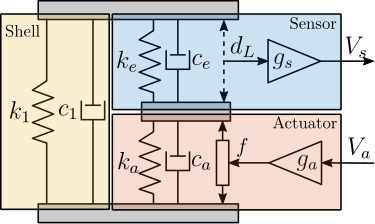
While providing computational efficiency, this simplified model has inherent limitations. It considers only axial behavior, treating the actuator as infinitely rigid in other directions. Several physical characteristics are not explicitly represented, including the mechanical amplification factor and the actual stress the piezoelectric stacks. Nevertheless, the model's primary advantage lies in its simplicity, adding only four states to the system model.
The model requires tuning of 8 parameters ($k_1$, $c_1$, $k_e$, $c_e$, $k_a$, $c_a$, $g_s$, and $g_a$) to match the dynamics extracted from the finite element analysis.
The shell parameters $k_1$ and $c_1$ were determined first through analysis of the zero in the $V_a$ to $V_s$ transfer function. The physical interpretation of this zero can be understood through Root Locus analysis: as controller gain increases, the poles of a closed-loop system converge to the open-loop zeros. The open-loop zero therefore corresponds to the poles of the system with a theoretical infinite-gain controller that ensures zero force in the sensor stack. This condition effectively represents the dynamics of an APA without the force sensor stack (i.e. an APA with only the shell). This physical interpretation enables straightforward parameter tuning: $k_1$ determines the frequency of the zero, while $c_1$ defines its damping characteristic.
The stack parameters ($k_a$, $c_a$, $k_e$, $c_e$) were then derived from the first pole of the $V_a$ to $y$ response. Given that identical piezoelectric stacks are used for both sensing and actuation, the relationships $k_e = 2k_a$ and $c_e = 2c_a$ were enforced, reflecting the series configuration of the dual actuator stacks. Finally, the sensitivities $g_s$ and $g_a$ were adjusted to match the DC gains of the respective transfer functions.
The resulting parameters, listed in Table ref:tab:detail_fem_apa300ml_2dof_parameters, yield dynamic behavior that closely matches the high-order finite element model, as demonstrated in Figure ref:fig:detail_fem_apa300ml_comp_fem_2dof_fem_2dof. While higher-order modes and non-axial flexibility are not captured, the model accurately represents the fundamental dynamics within the operational frequency range.
| Parameter | Value |
|---|---|
| $k_1$ | $0.30\,N/\mu m$ |
| $k_e$ | $4.3\, N/\mu m$ |
| $k_a$ | $2.15\,N/\mu m$ |
| $c_1$ | $18\,Ns/m$ |
| $c_e$ | $0.7\,Ns/m$ |
| $c_a$ | $0.35\,Ns/m$ |
| $g_a$ | $2.7\,N/V$ |
| $g_s$ | $0.53\,V/\mu m$ |
Electrical characteristics of the APA
<<ssec:detail_fem_actuator_apa300ml_electrical>>
The behavior of piezoelectric actuators is characterized by coupled constitutive equations that establish relationships between electrical properties (charges, voltages) and mechanical properties (stress, strain) cite:&schmidt20_desig_high_perfor_mechat_third_revis_edition, chapter 5.5.
To evaluate the impact of electrical boundary conditions on the system dynamics, experimental measurements were conducted using the APA95ML, comparing the transfer function from $V_a$ to $y$ under two distinct configurations. With the force sensor stack in open-circuit condition (analogous to voltage measurement with high input impedance) and in short-circuit condition (similar to charge measurement with low output impedance). As demonstrated in Figure ref:fig:detail_fem_apa95ml_effect_electrical_boundaries, short-circuiting the force sensor stack results in a minor decrease in resonance frequency. The developed models of the APA do not represent such behavior, but as this effect is quite small, this validates the simplifying assumption made in the models.
However, the electrical characteristics of the APA remain crucial for instrumentation design. Proper consideration must be given to voltage amplifier specifications and force sensor signal conditioning requirements. These aspects will be addressed in the instrumentation chapter.
Validation with the Nano-Hexapod
<<ssec:detail_fem_actuator_apa300ml_validation>>
The integration of the APA300ML model within the nano-hexapod simulation framework served two validation objectives: to validate the APA300ML choice through analysis of system dynamics with APA modelled as flexible bodies, and to validate the simplified 2DoF model through comparative analysis with the full FEM implementation.
The dynamics predicted using the flexible body model align well with the design requirements established during the conceptual phase. The dynamics from $\bm{u}$ to $\bm{V}_s$ exhibits the desired alternating pole-zero pattern (Figure ref:fig:detail_fem_actuator_fem_vs_perfect_hac_plant), a critical characteristic for implementing robust decentralized Integral Force Feedback. Additionally, the model predicts no problematic high-frequency modes in the dynamics from $\bm{u}$ to $\bm{\epsilon}_{\mathcal{L}}$ (Figure ref:fig:detail_fem_actuator_fem_vs_perfect_iff_plant), maintaining consistency with earlier conceptual simulations. These findings suggest that the control performance targets established during the conceptual phase remain achievable with the selected actuator.
Comparative analysis between the high-order FEM implementation and the simplified 2DoF model (Figure ref:fig:detail_fem_actuator_fem_vs_perfect_plants) demonstrates remarkable agreement in the frequency range of interest. This validates the use of the simplified model for time-domain simulations. The reduction in model order is substantial: while the FEM implementation results in approximately 300 states (36 states per actuator plus 12 additional states), the 2DoF model requires only 24 states for the complete nano-hexapod.
These results validate both the selection of the APA300ML and the effectiveness of the simplified modeling approach for the nano-hexapod.
Flexible Joint Design
<<sec:detail_fem_joint>>
Introduction
High-precision position control at the nanometer scale requires systems to be free from friction and backlash, as these nonlinear phenomena severely limit achievable positioning accuracy. This fundamental requirement prevents the use of conventional joints, necessitating instead the implementation of flexible joints that achieve motion through elastic deformation. For Stewart platforms requiring nanometric precision, numerous flexible joint designs have been developed and successfully implemented, as illustrated in Figure ref:fig:detail_fem_joints_examples. For design simplicity and component standardization, identical joints are employed at both ends of the nano-hexapod struts.
While ideally these joints would permit free rotation about defined axes while maintaining infinite rigidity in other degrees of freedom, practical implementations exhibit parasitic stiffness that can impact control performance cite:&mcinroy02_model_desig_flexur_joint_stewar. This section examines how these non-ideal characteristics affect system behavior, focusing particularly on bending/torsional stiffness (Section ref:ssec:detail_fem_joint_bending) and axial compliance (Section ref:ssec:detail_fem_joint_axial).
The analysis of bending and axial stiffness effects enables the establishment of comprehensive specifications for the flexible joints. These specifications guide the development and optimization of a flexible joint design through finite element analysis (Section ref:ssec:detail_fem_joint_specs). The validation process, detailed in Section ref:ssec:detail_fem_joint_validation, begins with the integration of the joints as "reduced order flexible bodies" in the nano-hexapod model, followed by the development of computationally efficient lower-order models that preserve the essential dynamic characteristics of the flexible joints.
Bending and Torsional Stiffness
<<ssec:detail_fem_joint_bending>>
The presence of bending stiffness in flexible joints causes the forces applied by the struts to deviate from the strut direction cite:&mcinroy02_model_desig_flexur_joint_stewar and can affect system dynamics.
To quantify these effects, simulations were conducted with the micro-station considered rigid and using simplified 1DoF actuators (stiffness of $1\,N/\mu m$) without parallel stiffness to the force sensors. Flexible joint bending stiffness was varied from 0 (ideal case) to $500\,Nm/\text{rad}$.
Analysis of the plant dynamics reveals two significant effects. For the transfer function from $\bm{f}$ to $\bm{\epsilon}_{\mathcal{L}}$, bending stiffness increases low-frequency coupling, though this remains small for realistic stiffness values (Figure ref:fig:detail_fem_joints_bending_stiffness_hac_plant). In cite:&mcinroy02_model_desig_flexur_joint_stewar, it is established that forces remain effectively aligned with the struts when the flexible joint bending stiffness is much small than the actuator stiffness multiplied by the square of the strut length. For the nano-hexapod, this corresponds to having the bending stiffness much lower than 9000 Nm/rad. This condition is more readily satisfied with the relatively stiff actuators selected, and could be problematic for softer Stewart platforms.
For the force sensor plant, bending stiffness introduces complex conjugate zeros at low frequency (Figure ref:fig:detail_fem_joints_bending_stiffness_iff_plant). This behavior resembles having parallel stiffness to the force sensor as was the case with the APA300ML (see Figure ref:fig:detail_fem_actuator_fem_vs_perfect_iff_plant). However, this time the parallel stiffness does not comes from the considered strut, but from the bending stiffness of the flexible joints of the other five struts. This characteristic impacts the achievable damping using decentralized Integral Force Feedback cite:&preumont07_six_axis_singl_stage_activ. This is confirmed by the Root Locus plot in Figure ref:fig:detail_fem_joints_bending_stiffness_iff_locus_1dof. This effect becomes less significant when using the selected APA300ML actuators (Figure ref:fig:detail_fem_joints_bending_stiffness_iff_locus_apa300ml), which already incorporate parallel stiffness by design which is higher than the one induced by flexible joint stiffness.
A parallel analysis of torsional stiffness revealed similar effects, though these proved less critical for system performance.
Axial Stiffness
<<ssec:detail_fem_joint_axial>>
The limited axial stiffness ($k_a$) of flexible joints introduces an additional compliance between the actuation point and the measurement point. As explained in cite:&preumont18_vibrat_contr_activ_struc_fourt_edition, chapter 6 and in cite:&rankers98_machin (effect called "actuator flexibility"), such intermediate flexibility invariably degrades control performance. Therefore, determining the minimum acceptable axial stiffness that maintains nano-hexapod performance becomes crucial.
The analysis incorporates the strut mass (112g per APA300ML) to accurately model internal resonance effects. A parametric study was conducted by varying the axial stiffness from $1\,N/\mu m$ (matching actuator stiffness) to $1000\,N/\mu m$ (approximating rigid behavior). The resulting frequency responses (Figure ref:fig:detail_fem_joints_axial_stiffness_plants) reveal distinct effects on system dynamics.
The force-sensor (IFF) plant exhibits minimal sensitivity to axial compliance, as evidenced by both frequency response data (Figure ref:fig:detail_fem_joints_axial_stiffness_iff_plant) and root locus analysis (Figure ref:fig:detail_fem_joints_axial_stiffness_iff_locus).
However, the transfer function from $\bm{f}$ to $\bm{\epsilon}_{\mathcal{L}}$ demonstrates significant effects: internal strut modes appear at high frequencies, introducing substantial cross-coupling between axes. This coupling is quantified through RGA analysis of the damped system (Figure ref:fig:detail_fem_joints_axial_stiffness_rga_hac_plant), which confirms increasing interaction between control channels at frequencies above the joint-induced resonance.
Above this resonance frequency, two critical limitations emerge. First, the system exhibits strong coupling between control channels, making decentralized control strategies ineffective. Second, control authority diminishes significantly near the resonant frequencies. These effects fundamentally limit achievable control bandwidth, making high axial stiffness essential for system performance.
Based on this analysis, an axial stiffness specification of $100\,N/\mu m$ was established for the nano-hexapod joints.
Specifications and Design flexible joints
<<ssec:detail_fem_joint_specs>>
The design of flexible joints for precision applications requires careful consideration of multiple mechanical characteristics. Critical specifications include sufficient bending stroke to ensure long-term operation below yield stress, high axial stiffness for precise positioning, low bending and torsional stiffnesses to minimize parasitic forces, adequate load capacity, and well-defined rotational axes. Based on the dynamic analysis presented in previous sections, quantitative specifications were established and are summarized in Table ref:tab:detail_fem_joints_specs.
| Specification | FEM | |
|---|---|---|
| Axial Stiffness $k_a$ | $> 100\,N/\mu m$ | 94 |
| Shear Stiffness $k_s$ | $> 1\,N/\mu m$ | 13 |
| Bending Stiffness $k_f$ | $< 100\,Nm/\text{rad}$ | 5 |
| Torsion Stiffness $k_t$ | $< 500\,Nm/\text{rad}$ | 260 |
| Bending Stroke | $> 1\,\text{mrad}$ | 24.5 |
Among various possible flexible joint architectures, the design shown in Figure ref:fig:detail_fem_joints_design was selected for three key advantages. First, the geometry creates coincident $x$ and $y$ rotation axes, ensuring well-defined kinematic behavior, important for the precise definition of the nano-hexapod Jacobian matrix. Second, the design allows easy tuning of different directional stiffnesses through a limited number of geometric parameters. Third, the architecture inherently provides high axial stiffness while maintaining the required compliance in rotational degrees of freedom.
The joint geometry was optimized through parametric finite element analysis. The optimization process revealed an inherent trade-off between maximizing axial stiffness and achieving sufficiently low bending/torsional stiffness, while maintaining material stresses within acceptable limits. The final design, featuring a neck dimension of 0.25mm, achieves mechanical properties closely matching the target specifications, as verified through finite element analysis and summarized in Table ref:tab:detail_fem_joints_specs.
Validation with the Nano-Hexapod
<<ssec:detail_fem_joint_validation>>
The designed flexible joint was first validated through integration into the nano-hexapod model using reduced-order flexible bodies derived from finite element analysis. This high-fidelity representation was created by defining two interface frames (Figure ref:fig:detail_fem_joints_frames) and extracting six additional modes, resulting in reduced-order mass and stiffness matrices of dimension $18 \times 18$. The computed transfer functions from actuator forces to both force sensor measurements ($\bm{f}$ to $\bm{f}_m$) and external metrology ($\bm{f}$ to $\bm{\epsilon}_{\mathcal{L}}$) demonstrate dynamics consistent with predictions from earlier analyses (Figure ref:fig:detail_fem_joints_fem_vs_perfect_plants), thereby validating the joint design.
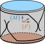
While this detailed modeling approach provides high accuracy, it results in a significant increase in system model order. The complete nano-hexapod model incorporates 240 states: 12 for the payload (6 DOF), 12 for the 2DOF struts, and 216 for the flexible joints (18 states for each of the 12 joints). To improve computational efficiency, a low order representation was developed using simplified joint elements with selective compliance DoF.
After evaluating various configurations, a compromise was achieved by modeling bottom joints with bending and axial stiffness ($k_f$ and $k_a$), and top joints with bending, torsional, and axial stiffness ($k_f$, $k_t$ and $k_a$). This simplification reduces the total model order to 48 states: 12 for the payload, 12 for the struts, and 24 for the joints (12 each for bottom and top joints). While additional degrees of freedom could potentially capture more dynamic features, the selected configuration preserves essential system characteristics while minimizing computational complexity.
Conclusion
<<sec:detail_fem_conclusion>>
In this chapter, the methodology of combining finite element analysis with multi-body modeling has been demonstrated and validated, proving particularly valuable for the detailed design of nano-hexapod components. The approach was first validated using an amplified piezoelectric actuator, where predicted dynamics showed excellent agreement with experimental measurements for both open and closed-loop behavior. This validation established confidence in the method's ability to accurately predict component behavior within a larger system.
The methodology was then successfully applied to optimize two critical components. For the actuators, it enabled validation of the APA300ML selection while providing both high-fidelity and computationally efficient models for system simulation. Similarly, for the flexible joints, the analysis of bending and axial stiffness effects led to clear specifications and an optimized design that balances competing mechanical requirements. In both cases, the ability to seamlessly integrate finite element models into the multi-body framework proved essential for understanding component interactions and their impact on system-level dynamics.
A key outcome of this work is the development of reduced-order models that maintain prediction accuracy while enabling efficient time-domain simulation. Such model reduction, guided by detailed understanding of component behavior, provides the foundation for subsequent control system design and optimization.
Control Optimization
<<sec:detail_control>>
Choice of Instrumentation
<<sec:detail_instrumentation>>
Introduction
This chapter presents an approach to select and validate appropriate instrumentation for the Nano Active Stabilization System (NASS), ensuring each component meets specific performance requirements. Figure ref:fig:detail_instrumentation_plant illustrates the control diagram with all relevant noise sources whose effects on sample position will be evaluated throughout this analysis.
The selection process follows a three-stage methodology. First, dynamic error budgeting is performed in Section ref:sec:detail_instrumentation_dynamic_error_budgeting to establish maximum acceptable noise specifications for each instrumentation component (ADC, DAC, and voltage amplifier). This analysis utilizes the multi-body model with a 2DoF APA model, focusing particularly on the vertical direction due to its more stringent requirements. From the calculated transfer functions, maximum acceptable amplitude spectral densities for each noise source are derived.
Section ref:sec:detail_instrumentation_choice then presents the selection of appropriate components based on these noise specifications and additional requirements.
Finally, Section ref:sec:detail_instrumentation_characterization validates the selected components through experimental testing. Each instrument is characterized individually, measuring actual noise levels and performance characteristics. The measured noise characteristics are then incorporated into the multi-body model to confirm that the combined effect of all instrumentation noise sources remains within acceptable limits.
\begin{tikzpicture}
  % Blocs
  \node[block={2.0cm}{2.0cm}, align=center] (plant) {NASS};

  \coordinate[] (inputVa)  at ($(plant.south west)!0.5!(plant.north west)$);
  \coordinate[] (outputVs) at ($(plant.south east)!0.7!(plant.north east)$);
  \coordinate[] (outputde) at ($(plant.south east)!0.3!(plant.north east)$);

  \node[addb={+}{}{}{}{}, left=0.8 of inputVa] (ampl_noise) {};
  \node[block={1.0cm}{1.0cm}, left=0.4 of ampl_noise] (ampl_tf) {$G_{\text{ampl}}$};

  \node[addb={+}{}{}{}{}, left=0.8 of ampl_tf] (dac_noise) {};
  \node[DAC, left=0.4 of dac_noise] (dac_tf) {};

  \node[addb={+}{}{}{}{}, left=1.0 of dac_tf] (iff_sum) {};

  \node[block={1.0cm}{1.0cm}, above=0.4 of iff_sum] (Kiff) {$\bm{K}_{\text{IFF}}$};
  \node[block={1.0cm}{1.0cm}, left=0.4 of iff_sum] (Khac) {$\bm{K}_{\text{HAC}}$};

  \node[addb={+}{}{}{}{}, right=0.8 of outputVs] (adc_noise) {};
  \node[ADC, right=0.4 of adc_noise] (adc_tf) {};

  \draw[->] (iff_sum.east)    --node[midway, above]{$\bm{u}$} node[near start, sloped]{$/$} (dac_tf.west);
  \draw[->] (dac_tf.east)     -- (dac_noise.west);
  \draw[->] (dac_noise.east)  -- (ampl_tf.west);
  \draw[->] (ampl_tf.east)    -- (ampl_noise.west);
  \draw[->] (ampl_noise.east)    -- (inputVa)node[above left]{$\bm{V}_a$};
  \draw[->] (outputVs)node[above right]{$\bm{V}_s$} -- (adc_noise.west);
  \draw[->] (adc_noise.east)     -- (adc_tf.west);
  \draw[->] (adc_tf.east)  -| ++(0.4, 1.8) -| node[near start, sloped]{$/$} (Kiff.north);
  \draw[->] (Kiff.south)       -- node[sloped]{$/$} (iff_sum.north);
  \draw[->] (outputde)node[above right]{$\bm{\epsilon}_{\mathcal{L}}$} -| ++(0.6, -1.0) -| node[near start, sloped]{$/$} ($(Khac.west)+(-0.6, 0)$) -- (Khac.west);
  \draw[->] (Khac.east)       -- node[sloped]{$/$} (iff_sum.west);

  \draw[<-] (dac_noise.north)  -- ++(0, 0.8)coordinate(dac_noise_input)  node[below left]{$n_{\text{da}}$};
  \draw[<-] (ampl_noise.north) -- ++(0, 0.8)coordinate(ampl_noise_input) node[below left]{$n_{\text{amp}}$};
  \draw[<-] (adc_noise.north)  -- ++(0, 0.8)coordinate(adc_noise_input)  node[below right]{$n_{\text{ad}}$};

  \begin{scope}[on background layer]
    \node[fit={(dac_tf.south west) (dac_noise.east|-dac_noise_input)}, fill=colorblue!20!white, draw, dashed, inner sep=4pt] (dac_system) {};
    \node[anchor={north}] at (dac_system.south){$\text{DAC}$};
  \end{scope}

  \begin{scope}[on background layer]
    \node[fit={(ampl_tf.south west) (ampl_noise.east|-ampl_noise_input)}, fill=colorred!20!white, draw, dashed, inner sep=4pt] (ampl_system) {};
    \node[anchor={north}] at (ampl_system.south){$\text{Amplifier}$};
  \end{scope}

  \begin{scope}[on background layer]
    \node[fit={(adc_noise.south -| adc_noise.west) (adc_tf.east|-adc_noise_input)}, fill=coloryellow!20!white, draw, dashed, inner sep=4pt] (adc_system) {};
    \node[anchor={north}] at (adc_system.south){$\text{ADC}$};
  \end{scope}

  \begin{scope}[on background layer]
    \node[fit={(Khac.south west) (Kiff.north east)}, fill=black!20!white, draw, dashed, inner sep=4pt] (control_system) {};
    \node[anchor={north}] at (control_system.south){$\text{RT Controller}$};
  \end{scope}
\end{tikzpicture}Dynamic Error Budgeting
<<sec:detail_instrumentation_dynamic_error_budgeting>>
Introduction
The primary goal of this analysis is to establish specifications for the maximum allowable noise levels of the instrumentation used for the NASS (ADC, DAC, and voltage amplifier) that would result in acceptable vibration levels in the system.
The procedure involves determining the closed-loop transfer functions from various noise sources to positioning error (Section ref:ssec:detail_instrumentation_cl_sensitivity). This analysis is conducted using the multi-body model with a 2-DoF Amplified Piezoelectric Actuator model that incorporates voltage inputs and outputs. Only the vertical direction is considered in this analysis as it presents the most stringent requirements; the horizontal directions are subject to less demanding constraints.
From these transfer functions, the maximum acceptable Amplitude Spectral Density (ASD) of the noise sources is derived (Section ref:ssec:detail_instrumentation_max_noise_specs). Since the voltage amplifier gain affects the amplification of DAC noise, an assumption of an amplifier gain of 20 was made.
Closed-Loop Sensitivity to Instrumentation Disturbances
<<ssec:detail_instrumentation_cl_sensitivity>>
Several key noise sources are considered in the analysis (Figure ref:fig:detail_instrumentation_plant). These include the output voltage noise of the DAC ($n_{da}$), the output voltage noise of the voltage amplifier ($n_{amp}$), and the voltage noise of the ADC measuring the force sensor stacks ($n_{ad}$).
Encoder noise, which is only used to estimate $R_z$, has been found to have minimal impact on the vertical sample error and is therefore omitted from this analysis for clarity.
The transfer functions from these three noise sources (for one strut) to the vertical error of the sample are estimated from the multi-body model, which includes the APA300ML and the designed flexible joints (Figure ref:fig:detail_instrumentation_noise_sensitivities).
Estimation of maximum instrumentation noise
<<ssec:detail_instrumentation_max_noise_specs>>
The most stringent requirement for the system is maintaining vertical vibrations below the smallest expected beam size of $100\,\text{nm}$, which corresponds to a maximum allowed vibration of $15\,\text{nm RMS}$.
Several assumptions regarding the noise characteristics have been made. The DAC, ADC, and amplifier noise are considered uncorrelated, which is a reasonable assumption. Similarly, the noise sources corresponding to each strut are also assumed to be uncorrelated. This means that the power spectral densities (PSD) of the different noise sources are summed.
Since the effect of each strut on the vertical error is identical due to symmetry, only one strut is considered for this analysis, and the total effect of the six struts is calculated as six times the effect of one strut in terms of power, which translates to a factor of $\sqrt{6} \approx 2.5$ for RMS values.
In order to derive specifications in terms of noise spectral density for each instrumentation component, a white noise profile is assumed, which is typical for these components.
The noise specification is computed such that if all components operate at their maximum allowable noise levels, the specification for vertical error will still be met. While this represents a pessimistic approach, it provides a reasonable estimate of the required specifications.
Based on this analysis, the obtained maximum noise levels are as follows: DAC maximum output noise ASD is established at $14\,\mu V/\sqrt{\text{Hz}}$, voltage amplifier maximum output voltage noise ASD at $280\,\mu V/\sqrt{\text{Hz}}$, and ADC maximum measurement noise ASD at $11\,\mu V/\sqrt{\text{Hz}}$. In terms of RMS noise, these translate to less than $1\,\text{mV RMS}$ for the DAC, less than $20\,\text{mV RMS}$ for the voltage amplifier, and less than $0.8\,\text{mV RMS}$ for the ADC.
If the Amplitude Spectral Density of the noise of the ADC, DAC, and voltage amplifiers all remain below these specified maximum levels, then the induced vertical error will be maintained below 15nm RMS.
Choice of Instrumentation
<<sec:detail_instrumentation_choice>>
Piezoelectric Voltage Amplifier
Introduction
Several characteristics of piezoelectric voltage amplifiers must be considered for this application. To take advantage of the full stroke of the piezoelectric actuator, the voltage output should range between $-20$ and $150\,V$. The amplifier should accept an analog input voltage, preferably in the range of $-10$ to $10\,V$, as this is standard for most DACs.
Small signal Bandwidth and Output Impedance
Small signal bandwidth is particularly important for feedback applications as it can limit the overall bandwidth of the complete feedback system.
A simplified electrical model of a voltage amplifier connected to a piezoelectric stack is shown in Figure ref:fig:detail_instrumentation_amp_output_impedance. This model is valid for small signals and provides insight into the small signal bandwidth limitation cite:&fleming14_desig_model_contr_nanop_system, chap. 14. In this model, $R_o$ represents the output impedance of the amplifier. When combined with the piezoelectric load (represented as a capacitance $C_p$), it forms a first order low pass filter described by eqref:eq:detail_instrumentation_amp_output_impedance.
\begin{equation}\label{eq:detail_instrumentation_amp_output_impedance} \frac{V_a}{V_i}(s) = \frac{1}{1 + \frac{s}{ω_0}}, \quad ω_0 = \frac{1}{R_o C_p}
\end{equation}
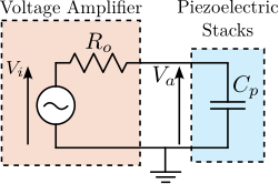
Consequently, the small signal bandwidth depends on the load capacitance and decreases as the load capacitance increases. For the APA300ML, the capacitive load of the two piezoelectric stacks corresponds to $C_p = 8.8\,\mu F$. If a small signal bandwidth of $f_0 = \frac{\omega_0}{2\pi} = 5\,\text{kHz}$ is desired, the voltage amplifier output impedance should be less than $R_0 = 3.6\,\Omega$.
Large signal Bandwidth
Large signal bandwidth relates to the maximum output capabilities of the amplifier in terms of amplitude as a function of frequency.
Since the primary function of the NASS is position stabilization rather than scanning, this specification is less critical than the small signal bandwidth. However, considering potential scanning capabilities, a worst-case scenario of a constant velocity scan (triangular reference signal) with a repetition rate of $f_r = 100\,\text{Hz}$ using the full voltage range of the piezoelectric actuator ($V_{pp} = 170\,V$) is considered.
There are two limiting factors for large signal bandwidth that should be evaluated:
- Slew rate, which should exceed $2 \cdot V_{pp} \cdot f_r = 34\,V/ms$. This requirement is typically easily met by commercial voltage amplifiers.
- Current output capabilities: as the capacitive impedance decreases inversely with frequency, it can reach very low values at high frequencies. To achieve high voltage at high frequency, the amplifier must therefore provide substantial current. The maximum required current can be calculated as $I_{\text{max}} = 2 \cdot V_{pp} \cdot f \cdot C_p = 0.3\,A$.
Therefore, ideally, a voltage amplifier capable of providing $0.3\,A$ of current would be interesting for scanning applications.
Output voltage noise
As established in Section ref:sec:detail_instrumentation_dynamic_error_budgeting, the output noise of the voltage amplifier should be below $20\,\text{mV RMS}$.
It should be noted that the load capacitance of the piezoelectric stack filters the output noise of the amplifier, as illustrated by the low pass filter in Figure ref:fig:detail_instrumentation_amp_output_impedance. Therefore, when comparing noise specifications from different voltage amplifier datasheets, it is essential to verify the capacitance of the load used during the measurement cite:&spengen20_high_voltag_amplif.
For this application, the output noise must remain below $20\,\text{mV RMS}$ with a load of $8.8\,\mu F$ and a bandwidth exceeding $5\,\text{kHz}$.
Choice of voltage amplifier
The specifications are summarized in Table ref:tab:detail_instrumentation_amp_choice. The most critical characteristics are the small signal bandwidth ($>5\,\text{kHz}$) and the output voltage noise ($<20\,\text{mV RMS}$).
Several voltage amplifiers were considered, with their datasheet information presented in Table ref:tab:detail_instrumentation_amp_choice. One challenge encountered during the selection process was that manufacturers typically do not specify output noise as a function of frequency (i.e., the ASD of the noise), but instead provide only the RMS value, which represents the integrated value across all frequencies. This approach does not account for the frequency dependency of the noise, which is crucial for accurate error budgeting.
Additionally, the load conditions used to estimate bandwidth and noise specifications are often not explicitly stated. In many cases, bandwidth is reported with minimal load while noise is measured with substantial load, making direct comparisons between different models more complex.
The PD200 from PiezoDrive was ultimately selected because it meets all the requirements and is accompanied by clear documentation, particularly regarding noise characteristics and bandwidth specifications.
| Specification | PD200 | WMA-200 | LA75B | E-505 |
|---|---|---|---|---|
| PiezoDrive | Falco | Cedrat | PI | |
| Input Voltage Range: $\pm 10\,V$ | $\pm 10\,V$ | $\pm8.75\,V$ | $-1/7.5\,V$ | |
| Output Voltage Range: $-20/150\,V$ | $-50/150\,V$ | $\pm 175\,V$ | $-20/150\,V$ | -30/130 |
| Gain $>15$ | 20 | 20 | 20 | 10 |
| Output Current $> 300\,mA$ | $900\,mA$ | $150\,mA$ | $360\,mA$ | $215\,mA$ |
| Slew Rate $> 34\,V/ms$ | $150\,V/\mu s$ | $80\,V/\mu s$ | n/a | n/a |
| Output noise $< 20\,mV\ \text{RMS}$ | $0.7\,mV\,\text{RMS}$ | $0.05\,mV$ | $3.4\,mV$ | $0.6\,mV$ |
| (10uF load) | ($10\,\mu F$ load) | ($10\,\mu F$ load) | (n/a) | (n/a) |
| Small Signal Bandwidth $> 5\,kHz$ | $6.4\,kHz$ | $300\,Hz$ | $30\,kHz$ | n/a |
| ($10\,\mu F$ load) | ($10\,\mu F$ load) | 26 | (unloaded) | (n/a) |
| Output Impedance: $< 3.6\,\Omega$ | n/a | $50\,\Omega$ | n/a | n/a |
ADC and DAC
Introduction
Analog-to-digital converters and digital-to-analog converters play key roles in the system, serving as the interface between the digital RT controller and the analog physical plant. The proper selection of these components is critical for system performance.
Synchronicity and Jitter
For control systems, synchronous sampling of inputs and outputs of the real-time controller and minimal jitter are essential requirements cite:&abramovitch22_pract_method_real_world_contr_system;&abramovitch23_tutor_real_time_comput_issues_contr_system.
Therefore, the ADC and DAC must be well interfaced with the Speedgoat real-time controller and triggered synchronously with the computation of the control signals. Based on this requirement, priority was given to ADC and DAC components specifically marketed by Speedgoat to ensure optimal integration.
Sampling Frequency, Bandwidth and delays
Several requirements that may initially appear similar are actually distinct in nature.
First, the sampling frequency defines the interval between two sampled points and determines the Nyquist frequency. Then, the bandwidth specifies the maximum frequency of a measured signal (typically defined as the -3dB point) and is often limited by implemented anti-aliasing filters. Finally, delay (or latency) refers to the time interval between the analog signal at the input of the ADC and the digital information transferred to the control system.
Sigma-Delta ADCs can provide excellent noise characteristics, high bandwidth, and high sampling frequency, but often at the cost of poor latency. Typically, the latency can reach 20 times the sampling period cite:&schmidt20_desig_high_perfor_mechat_third_revis_edition, chapt. 8.4. Consequently, while Sigma-Delta ADCs are widely used for signal acquisition applications, they have limited utility in real-time control scenarios where latency is a critical factor.
For real-time control applications, SAR-ADCs (Successive Approximation ADCs) remain the predominant choice due to their single-sample latency characteristics.
ADC Noise
Based on the dynamic error budget established in Section ref:sec:detail_instrumentation_dynamic_error_budgeting, the measurement noise ASD should not exceed $11\,\mu V/\sqrt{\text{Hz}}$.
ADCs are subject to various noise sources. Quantization noise, which results from the discrete nature of digital representation, is one of these sources. To determine the minimum bit depth $n$ required to meet the noise specifications, an ideal ADC where quantization error is the only noise source is considered.
The quantization step size, denoted as $q = \Delta V/2^n$, represents the voltage equivalent of the least significant bit, with $\Delta V$ the full range of the ADC in volts, and $F_s$ the sampling frequency in Hertz.
The quantization noise ranges between $\pm q/2$, and its probability density function is constant across this range (uniform distribution). Since the integral of this probability density function $p(e)$ equals one, its value is $1/q$ for $-q/2 < e < q/2$, as illustrated in Figure ref:fig:detail_instrumentation_adc_quantization.
\begin{tikzpicture}
  \path[fill=black!20!white] (-1, 0) |- (1, 1) |- (-1, 0);

  \draw[->] (-2, 0) -- (2, 0) node[above left]{$e$};
  \draw[->] (0, -0.5) -- (0, 2) node[below right]{$p(e)$};
  \draw[dashed] (-2, 0) -- (-1, 0) |- (1, 1) |- (2, 0);

  \node[below] at (1, 0){$\frac{q}{2}$};
  \node[below] at (-1, 0){$-\frac{q}{2}$};
  \node[right] at (1, 1){$\frac{1}{q}$};
\end{tikzpicture}The variance (or time-average power) of the quantization noise is expressed by eqref:eq:detail_instrumentation_quant_power.
\begin{equation}\label{eq:detail_instrumentation_quant_power} P_q = ∫-q/2q/2 e^2 p(e) de = \frac{q^2}{12}
\end{equation}
To compute the power spectral density of the quantization noise, which is defined as the Fourier transform of the noise's autocorrelation function, it is assumed that noise samples are uncorrelated. Under this assumption, the autocorrelation function approximates a delta function in the time domain. Since the Fourier transform of a delta function equals one, the power spectral density becomes frequency-independent (white noise).
By Parseval's theorem, the power spectral density of the quantization noise $\Phi_q$ can be linked to the ADC sampling frequency and quantization step size eqref:eq:detail_instrumentation_psd_quant_noise.
\begin{equation}\label{eq:detail_instrumentation_psd_quant_noise} ∫-F_s/2F_s/2 Φ_q(f) d f = ∫-q/2q/2 e^2 p(e) de \quad \Longrightarrow \quad Φ_q = \frac{q^2}{12 F_s} = \frac{≤ft(\frac{Δ V}{2^n}\right)^2}{12 F_s} \quad \text{in } ≤ft[ \frac{V^2}{\text{Hz}} \right]
\end{equation}
From a specified noise amplitude spectral density $\Gamma_{\text{max}}$, the minimum number of bits required to keep quantization noise below $\Gamma_{\text{max}}$ is calculated using eqref:eq:detail_instrumentation_min_n.
\begin{equation}\label{eq:detail_instrumentation_min_n} n = \text{log}_2 ≤ft( \frac{Δ V}{\sqrt{12 F_s} ⋅ Γ_{\text{max}}} \right)
\end{equation}
With a sampling frequency $F_s = 10\,\text{kHz}$, an input range $\Delta V = 20\,V$ and a maximum allowed ASD $\Gamma_{\text{max}} = 11\,\mu V/\sqrt{Hz}$, the minimum number of bits is $n_{\text{min}} = 12.4$, which is readily achievable with commercial ADCs.
DAC Output voltage noise
Similar to the ADC requirements, the DAC output voltage noise ASD should not exceed $14\,\mu V/\sqrt{\text{Hz}}$. This specification corresponds to a $\pm 10\,V$ DAC with 13-bit resolution, which is easily attainable with current technology.
Choice of the ADC and DAC Board
Based on the preceding analysis, the selection of suitable ADC and DAC components is straightforward.
For optimal synchronicity, a Speedgoat-integrated solution was chosen. The selected model is the IO131, which features 16 analog inputs based on the AD7609 with 16-bit resolution, $\pm 10\,V$ range, maximum sampling rate of 200kSPS, simultaneous sampling, and differential inputs allowing the use of shielded twisted pairs for enhanced noise immunity. The board also includes 8 analog outputs based on the AD5754R with 16-bit resolution, $\pm 10\,V$ range, conversion time of $10\,\mu s$, and simultaneous update capability.
Although noise specifications are not explicitly provided in the datasheet, the 16-bit resolution should ensure performance well below the established requirements. This will be experimentally verified in Section ref:sec:detail_instrumentation_characterization.
Relative Displacement Sensors
The specifications for the relative displacement sensors include sufficient compactness for integration within each strut, noise levels below $6\,\text{nm RMS}$ (derived from the $15\,\text{nm RMS}$ vertical error requirement for the system divided by the contributions of six struts), and a measurement range exceeding $100\,\mu m$.
Several sensor technologies are capable of meeting these requirements cite:&fleming13_review_nanom_resol_posit_sensor. These include optical encoders (Figure ref:fig:detail_instrumentation_sensor_encoder), capacitive sensors (Figure ref:fig:detail_instrumentation_sensor_capacitive), and eddy current sensors (Figure ref:fig:detail_instrumentation_sensor_eddy_current), each with their own advantages and implementation considerations.
From an implementation perspective, capacitive and eddy current sensors offer a slight advantage as they can be quite compact and can measure in line with the APA, as illustrated in Figure ref:fig:detail_instrumentation_capacitive_implementation. In contrast, optical encoders are bigger and they must be offset from the strut's action line, which introduces potential measurement errors (Abbe errors) due to potential relative rotations between the two ends of the APA, as shown in Figure ref:fig:detail_instrumentation_encoder_implementation.
A significant consideration in the sensor selection process was the fact that sensor signals must pass through an electrical slip-ring due to the continuous spindle rotation. Measurements conducted on the slip-ring integrated in the micro-station revealed substantial cross-talk between different slip-ring channels. To mitigate this issue, preference was given to sensors that transmit displacement measurements digitally, as these are inherently less susceptible to noise and cross-talk. Based on this criterion, an optical encoder with digital output was selected, where signal interpolation is performed directly in the sensor head.
The specifications of the considered relative motion sensor, the Renishaw Vionic, are summarized in Table ref:tab:detail_instrumentation_sensor_specs, alongside alternative options that were considered.
| Specification | Renishaw Vionic | LION CPL190 | Cedrat ECP500 |
|---|---|---|---|
| Technology | Digital Encoder | Capacitive | Eddy Current |
| Bandwidth $> 5\,\text{kHz}$ | $> 500\,\text{kHz}$ | 10kHz | 20kHz |
| Noise $< 6\,nm\,\text{RMS}$ | 1.6 nm rms | 4 nm rms | 15 nm rms |
| Range $> 100\,\mu m$ | Ruler length | 250 um | 500um |
| In line measurement | $\times$ | $\times$ | |
| Digital Output | $\times$ |
Characterization of Instrumentation
<<sec:detail_instrumentation_characterization>>
Analog to Digital Converters
Measured Noise
The measurement of ADC noise was performed by short-circuiting its input with a $50\,\Omega$ resistor and recording the digital values at a sampling rate of $10\,\text{kHz}$. The amplitude spectral density of the recorded values was computed and is presented in Figure ref:fig:detail_instrumentation_adc_noise_measured. The ADC noise exhibits characteristics of white noise with an amplitude spectral density of $5.6\,\mu V/\sqrt{\text{Hz}}$ (equivalent to $0.4\,\text{mV RMS}$), which satisfies the established specifications. All ADC channels demonstrated similar performance, so only one channel's noise profile is shown.
If necessary, oversampling can be applied to further reduce the noise cite:lab13_improv_adc. To gain $w$ additional bits of resolution, the oversampling frequency $f_{os}$ should be set to $f_{os} = 4^w \cdot F_s$. Given that the ADC can operate at 200kSPS while the real-time controller runs at 10kSPS, an oversampling factor of 16 can be employed to gain approximately two additional bits of resolution (reducing noise by a factor of 4). This approach is effective because the noise approximates white noise and its amplitude exceeds 1 LSB (0.3 mV) cite:hauser91_princ_overs_conver.
Reading of piezoelectric force sensor
To further validate the ADC's capability to effectively measure voltage generated by a piezoelectric stack, a test was conducted using the APA95ML. The setup is illustrated in Figure ref:fig:detail_instrumentation_force_sensor_adc_setup, where two stacks are used as actuators (connected in parallel) and one stack serves as a sensor. The voltage amplifier employed in this setup has a gain of 20.

Step signals with an amplitude of $1\,V$ were generated using the DAC, and the ADC signal was recorded. The excitation signal (steps) and the measured voltage across the sensor stack are displayed in Figure ref:fig:detail_instrumentation_step_response_force_sensor.
Two notable observations were made: an offset voltage of $2.26\,V$ was present, and the measured voltage exhibited an exponential decay response to the step input. These phenomena can be explained by examining the electrical schematic shown in Figure ref:fig:detail_instrumentation_force_sensor_adc, where the ADC has an input impedance $R_i$ and an input bias current $i_n$.
The input impedance $R_i$ of the ADC, in combination with the capacitance $C_p$ of the piezoelectric stack sensor, forms an RC circuit with a time constant $\tau = R_i C_p$. The charge generated by the piezoelectric effect across the stack's capacitance gradually discharges into the input resistor of the ADC. Consequently, the transfer function from the generated voltage $V_p$ to the measured voltage $V_{\text{ADC}}$ is a first-order high-pass filter with the time constant $\tau$.
An exponential curve was fitted to the experimental data, yielding a time constant $\tau = 6.5\,s$. With the capacitance of the piezoelectric sensor stack being $C_p = 4.4\,\mu F$, the internal impedance of the Speedgoat ADC was calculated as $R_i = \tau/C_p = 1.5\,M\Omega$, which closely aligns with the specified value of $1\,M\Omega$ found in the datasheet.
The constant voltage offset can be explained by the input bias current $i_n$ of the ADC, represented in Figure ref:fig:detail_instrumentation_force_sensor_adc. At DC, the impedance of the piezoelectric stack is much larger than the input impedance of the ADC, and therefore the input bias current $i_n$ passing through the internal resistance $R_i$ produces a constant voltage offset $V_{\text{off}} = R_i \cdot i_n$. The input bias current $i_n$ is estimated from $i_n = V_{\text{off}}/R_i = 1.5\mu A$.
In order to reduce the input voltage offset and to increase the corner frequency of the high pass filter, a resistor $R_p$ can be added in parallel to the force sensor, as illustrated in Figure ref:fig:detail_instrumentation_force_sensor_adc_R. This modification produces two beneficial effects: a reduction of input voltage offset through the relationship $V_{\text{off}} = (R_p R_i)/(R_p + R_i) i_n$, and an increase in the high pass corner frequency $f_c$ according to the equations $\tau = 1/(2\pi f_c) = (R_i R_p)/(R_i + R_p) C_p$.
To validate this approach, a resistor $R_p \approx 82\,k\Omega$ was added in parallel with the force sensor as shown in Figure ref:fig:detail_instrumentation_force_sensor_adc_R. After incorporating this resistor, the same step response tests were performed, with results displayed in Figure ref:fig:detail_instrumentation_step_response_force_sensor_R. The measurements confirmed the expected improvements, with a substantially reduced offset voltage ($V_{\text{off}} = 0.15\,V$) and a much faster time constant ($\tau = 0.45\,s$). These results validate both the model of the ADC and the effectiveness of the added parallel resistor as a solution.
Instrumentation Amplifier
Because the ADC noise may be too low to measure the noise of other instruments (anything below $5.6\,\mu V/\sqrt{\text{Hz}}$ cannot be distinguished from the noise of the ADC itself), a low noise instrumentation amplifier was employed. A Femto DLPVA-101-B-S amplifier with adjustable gains from 20dB up to 80dB was selected for this purpose.
The first step was to characterize the input27 noise of the amplifier. This was accomplished by short-circuiting its input with a $50\,\Omega$ resistor and measuring the output voltage with the ADC (Figure ref:fig:detail_instrumentation_femto_meas_setup). The maximum amplifier gain of 80dB (equivalent to 10000) was used for this measurement.
The measured voltage $n$ was then divided by 10000 to determine the equivalent noise at the input of the voltage amplifier $n_a$. In this configuration, the noise contribution from the ADC $q_{ad}$ is rendered negligible due to the high gain employed. The resulting amplifier noise amplitude spectral density $\Gamma_{n_a}$ and the (negligible) contribution of the ADC noise are presented in Figure ref:fig:detail_instrumentation_femto_input_noise.
\begin{tikzpicture}
  \node[block={0.6cm}{0.6cm}] (const) {$0$};
  % Pre Amp
  \node[addb, right=0.4 of const] (addna) {};
  \node[block, right=0.3 of addna] (Ga) {$G_a(s)$};

  % ADC
  \node[addb, right=0.8 of Ga] (addqad){};
  \node[ADC, right=0.3 of addqad] (ADC) {ADC};

  \draw[->] (const.east) -- (addna.west);
  \draw[->] (addna.east) -- (Ga.west);
  \draw[->] (Ga.east)    -- (addqad.west);
  \draw[->] (addqad.east) -- (ADC.west);
  \draw[->] (ADC.east)    -- node[sloped]{$/$} ++(0.8, 0) node[above left]{$n$};

  \draw[<-] (addna.north)  -- ++(0, 0.6) node[below right](na){$n_{a}$};
  \draw[<-] (addqad.north) -- ++(0, 0.6) node[below right](qad){$q_{ad}$};

  \coordinate[] (top) at (na.north);
  \coordinate[] (bot) at (Ga.south);

  % 5113
  \begin{scope}[on background layer]
    \node[fit={(addna.west|-bot) (Ga.east|-top)}, inner sep=4pt, draw, dashed, fill=colorgreen!20!white] (P) {};
    \node[above] at (P.north) {Pre Amp};
  \end{scope}

  % ADC
  \begin{scope}[on background layer]
    \node[fit={(addqad.west|-bot) (ADC.east|-top)}, inner sep=4pt, draw, dashed, fill=coloryellow!20!white] (P) {};
    \node[above] at (P.north) {ADC};
  \end{scope}
\end{tikzpicture}
\hfill
Digital to Analog Converters
Output Voltage Noise
To measure the output noise of the DAC, the setup schematically represented in Figure ref:fig:detail_instrumentation_dac_setup was utilized. The DAC was configured to output a constant voltage (zero in this case), and the gain of the pre-amplifier was adjusted such that the measured amplified noise was significantly larger than the noise of the ADC.
The Amplitude Spectral Density $\Gamma_{n_{da}}(\omega)$ of the measured signal was computed, and verification was performed to confirm that the contributions of ADC noise and amplifier noise were negligible in the measurement.
The resulting Amplitude Spectral Density of the DAC's output voltage is displayed in Figure ref:fig:detail_instrumentation_dac_output_noise. The noise profile is predominantly white with an ASD of $0.6\,\mu V/\sqrt{\text{Hz}}$. Minor $50\,\text{Hz}$ noise is present, along with some low frequency $1/f$ noise, but these are not expected to pose issues as they are well within specifications. It should be noted that all DAC channels demonstrated similar performance, so only one channel measurement is presented.
\begin{tikzpicture}
  \node[block={0.6cm}{0.6cm}] (const) {$0$};

  % DAC
  \node[DAC, right=0.4 of const] (DAC) {DAC};
  \node[addb, right=0.3 of DAC] (addnda){};

  % Pre Amp
  \node[addb, right=0.8 of addnda] (addna) {};
  \node[block, right=0.3 of addna] (Ga) {$G_a(s)$};

  % ADC
  \node[addb, right=0.8 of Ga] (addqad){};
  \node[ADC, right=0.3 of addqad] (ADC) {ADC};

  \draw[->] (const.east) -- node[sloped]{$/$} (DAC.west);
  \draw[->] (DAC.east) -- (addnda.west);
  \draw[->] (addnda.east) -- (addna.west);
  \draw[->] (addna.east) -- (Ga.west);
  \draw[->] (Ga.east) -- (addqad.west);
  \draw[->] (addqad.east) -- (ADC.west);
  \draw[->] (ADC.east) -- node[sloped]{$/$} ++(0.8, 0);

  \draw[<-] (addnda.north) -- ++(0, 0.6) node[below left](nda){$n_{da}$};
  \draw[<-] (addna.north)  -- ++(0, 0.6) node[below right](na){$n_{a}$};
  \draw[<-] (addqad.north) -- ++(0, 0.6) node[below right](qad){$q_{ad}$};

  \coordinate[] (top) at (na.north);
  \coordinate[] (bot) at (Ga.south);

  % DAC
  \begin{scope}[on background layer]
    \node[fit={(DAC.west|-bot) (addnda.east|-top)}, inner sep=4pt, draw, dashed, fill=colorblue!20!white] (P) {};
    \node[above] at (P.north) {DAC};
  \end{scope}

  % 5113
  \begin{scope}[on background layer]
    \node[fit={(addna.west|-bot) (Ga.east|-top)}, inner sep=4pt, draw, dashed, fill=colorgreen!20!white] (P) {};
    \node[above] at (P.north) {Pre Amp};
  \end{scope}

  % ADC
  \begin{scope}[on background layer]
    \node[fit={(addqad.west|-bot) (ADC.east|-top)}, inner sep=4pt, draw, dashed, fill=coloryellow!20!white] (P) {};
    \node[above] at (P.north) {ADC};
  \end{scope}
\end{tikzpicture}Delay from ADC to DAC
To measure the transfer function from DAC to ADC and verify that the bandwidth and latency of both instruments is sufficient, a direct connection was established between the DAC output and the ADC input. A white noise signal was generated by the DAC, and the ADC response was recorded.
The resulting frequency response function from the digital DAC signal to the digital ADC signal is presented in Figure ref:fig:detail_instrumentation_dac_adc_tf. The observed frequency response function corresponds to exactly one sample delay, which aligns with the specifications provided by the manufacturer.
Piezoelectric Voltage Amplifier
Output Voltage Noise
The measurement setup for evaluating the PD200 amplifier noise is illustrated in Figure ref:fig:detail_instrumentation_pd200_setup. The input of the PD200 amplifier was shunted with a $50\,\Ohm$ resistor to ensure that only the inherent noise of the amplifier itself was measured. The pre-amplifier gain was increased to produce a signal substantially larger than the noise floor of the ADC. Two piezoelectric stacks from the APA95ML were connected to the PD200 output to provide an appropriate load for the amplifier.
\begin{tikzpicture}
  \node[block={0.6cm}{0.6cm}] (const) {$0$};

  % PD200
  \node[block, right=0.4 of const] (Gp){$G_p(s)$};
  \node[addb, right=0.3 of Gp] (addnp){};

  % Pre Amp
  \node[addb, right=0.8 of addnp] (addna) {};
  \node[block, right=0.3 of addna] (Ga) {$G_a(s)$};

  % ADC
  \node[addb, right=0.8 of Ga] (addqad){};
  \node[ADC, right=0.3 of addqad] (ADC) {ADC};

  \draw[->] (const.east) -- (Gp.west);
  \draw[->] (Gp.east) -- (addnp.west);
  \draw[->] (addnp.east) -- (addna.west);
  \draw[->] (addna.east) -- (Ga.west);
  \draw[->] (Ga.east) -- (addqad.west);
  \draw[->] (addqad.east) -- (ADC.west);
  \draw[->] (ADC.east) -- node[sloped]{$/$} ++(0.8, 0) node[above left]{$n$};

  \draw[<-] (addnp.north) -- ++(0, 0.6) node[below left](np){$n_{p}$};
  \draw[<-] (addna.north) -- ++(0, 0.6) node[below right](na){$n_{a}$};
  \draw[<-] (addqad.north) -- ++(0, 0.6) node[below right](qad){$q_{ad}$};

  \coordinate[] (top) at (na.north);
  \coordinate[] (bot) at (Ga.south);

  % PD200
  \begin{scope}[on background layer]
    \node[fit={(addnp.east|-bot) (Gp.west|-top)}, inner sep=4pt, draw, dashed, fill=colorred!20!white] (P) {};
    \node[above] at (P.north) {PD200};
  \end{scope}

  % 5113
  \begin{scope}[on background layer]
    \node[fit={(addna.west|-bot) (Ga.east|-top)}, inner sep=4pt, draw, dashed, fill=colorgreen!20!white] (P) {};
    \node[above] at (P.north) {Pre Amp};
  \end{scope}

  % ADC
  \begin{scope}[on background layer]
    \node[fit={(addqad.west|-bot) (ADC.east|-top)}, inner sep=4pt, draw, dashed, fill=coloryellow!20!white] (P) {};
    \node[above] at (P.north) {ADC};
  \end{scope}
\end{tikzpicture}The Amplitude Spectral Density $\Gamma_{n}(\omega)$ of the signal measured by the ADC was computed. From this, the Amplitude Spectral Density of the output voltage noise of the PD200 amplifier $n_p$ was derived, accounting for the gain of the pre-amplifier according to eqref:eq:detail_instrumentation_amp_asd.
\begin{equation}\label{eq:detail_instrumentation_amp_asd} Γn_p(ω) = \frac{Γ_n(ω)}{|G_p(jω) G_a(jω)|}
\end{equation}
The computed Amplitude Spectral Density of the PD200 output noise is presented in Figure ref:fig:detail_instrumentation_pd200_noise. Verification was performed to confirm that the measured noise was predominantly from the PD200, with negligible contributions from the pre-amplifier noise or ADC noise. The measurements from all six amplifiers are displayed in this figure.
The noise spectrum of the PD200 amplifiers exhibits several sharp peaks. While the exact cause of these peaks is not fully understood, their amplitudes remain below the specified limits and should not adversely affect system performance.
Small Signal Bandwidth
The small signal dynamics of all six PD200 amplifiers were characterized through frequency response measurements.
A logarithmic sweep sine excitation voltage was generated using the Speedgoat DAC with an amplitude of $0.1\,V$, spanning frequencies from $1\,\text{Hz}$ to $5\,\text{kHz}$. The output voltage of the PD200 amplifier was measured via the monitor voltage output of the amplifier, while the input voltage (generated by the DAC) was measured with a separate ADC channel of the Speedgoat system. This measurement approach eliminates the influence of ADC-DAC-related time delays in the results.
All six amplifiers demonstrated consistent transfer function characteristics. The amplitude response remains constant across a wide frequency range, and the phase shift is limited to less than 1 degree up to 500Hz, well within the specified requirements.
The identified dynamics shown in Figure ref:fig:detail_instrumentation_pd200_tf can be accurately modeled as either a first-order low-pass filter or as a simple constant gain.
Linear Encoders
To measure the noise of the encoder, the head and ruler were rigidly fixed together to ensure that no relative motion would be detected. Under these conditions, any measured signal would correspond solely to the encoder noise.
The measurement setup is shown in Figure ref:fig:detail_instrumentation_vionic_bench. To minimize environmental disturbances, the entire bench was covered with a plastic bubble sheet during measurements.
The amplitude spectral density of the measured displacement (which represents the measurement noise) is presented in Figure ref:fig:detail_instrumentation_vionic_asd. The noise profile exhibits characteristics of white noise with an amplitude of approximately $1\,\text{nm RMS}$, which complies with the system requirements.
\hfill
Noise budgeting from measured instrumentation noise
After characterizing all instrumentation components individually, their combined effect on the sample's vibration was assessed using the multi-body model developed earlier.
The vertical motion induced by the noise sources, specifically the ADC noise, DAC noise, and voltage amplifier noise, is presented in Figure ref:fig:detail_instrumentation_cl_noise_budget.
The total motion induced by all noise sources combined is approximately $1.5\,\text{nm RMS}$, which remains well within the specified limit of $15\,\text{nm RMS}$. This confirms that the selected instrumentation, with its measured noise characteristics, is suitable for the intended application.
Conclusion
<<sec:detail_instrumentation_conclusion>>
This section has presented a comprehensive approach to the selection and characterization of instrumentation for the nano active stabilization system. The multi-body model created earlier served as a key tool for embedding instrumentation components and their associated noise sources within the system analysis. From the most stringent requirement (i.e. the specification on vertical sample motion limited to 15 nm RMS), detailed specifications for each noise source were methodically derived through dynamic error budgeting.
Based on these specifications, appropriate instrumentation components were selected for the system. The selection process revealed certain challenges, particularly with voltage amplifiers, where manufacturer datasheets often lacked crucial information needed for accurate noise budgeting, such as amplitude spectral densities under specific load conditions. Despite these challenges, suitable components were identified that theoretically met all requirements.
The selected instrumentation (including the IO131 ADC/DAC from Speedgoat, PD200 piezoelectric voltage amplifiers from PiezoDrive, and Vionic linear encoders from Renishaw) was procured and thoroughly characterized. Initial measurements of the ADC system revealed an issue with force sensor readout related to input bias current, which was successfully addressed by adding a parallel resistor to optimize the measurement circuit.
All components were found to meet or exceed their respective specifications. The ADC demonstrated noise levels of $5.6\,\mu V/\sqrt{\text{Hz}}$ (versus the $11\,\mu V/\sqrt{\text{Hz}}$ specification), the DAC showed $0.6\,\mu V/\sqrt{\text{Hz}}$ (versus $14\,\mu V/\sqrt{\text{Hz}}$ required), the voltage amplifiers exhibited noise well below the $280\,\mu V/\sqrt{\text{Hz}}$ limit, and the encoders achieved $1\,\text{nm RMS}$ noise (versus the $6\,\text{nm RMS}$ specification).
Finally, the measured noise characteristics of all instrumentation components were included into the multi-body model to predict the actual system performance. The combined effect of all noise sources was estimated to induce vertical sample vibrations of only $1.5\,\text{nm RMS}$, which is substantially below the $15\,\text{nm RMS}$ requirement. This rigorous methodology spanning requirement formulation, component selection, and experimental characterization validates the instrumentation's ability to fulfill the nano active stabilization system's demanding performance specifications.
Obtained Design
<<sec:detail_design>>
- Explain again the different specifications in terms of space, payload, etc..
- CAD view of the nano-hexapod
- Chosen geometry, materials, ease of mounting, cabling, …
- Validation on Simscape with accurate model?
Detailed Design - Conclusion
<<sec:detail_conclusion>>
Experimental Validation
<<chap:test>> minitoc
Amplified Piezoelectric Actuator
<<sec:test_apa>>
Introduction
In this chapter, the goal is to ensure that the received APA300ML (shown in Figure ref:fig:test_apa_received) are complying with the requirements and that the dynamical models of the actuator accurately represent its dynamics.
In section ref:sec:test_apa_basic_meas, the mechanical tolerances of the APA300ML interfaces are checked together with the electrical properties of the piezoelectric stacks and the achievable stroke. The flexible modes of the APA300ML, which were estimated using a finite element model, are compared with measurements.
Using a dedicated test bench, dynamical measurements are performed (Section ref:sec:test_apa_dynamics). The dynamics from the generated DAC voltage (going through the voltage amplifier and then to two actuator stacks) to the induced axial displacement and to the measured voltage across the force sensor stack are estimated. Integral Force Feedback is experimentally applied, and the damped plants are estimated for several feedback gains.
Two different models of the APA300ML are presented. First, in Section ref:sec:test_apa_model_2dof, a two degrees-of-freedom model is presented, tuned, and compared with the measured dynamics. This model is proven to accurately represent the APA300ML's axial dynamics while having low complexity.
Then, in Section ref:sec:test_apa_model_flexible, a super element of the APA300ML is extracted using a finite element model and imported into the multi-body model. This more complex model also captures well capture the axial dynamics of the APA300ML.
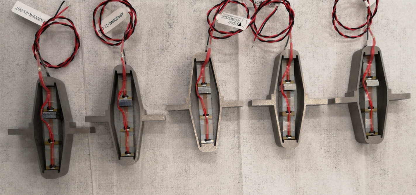
First Basic Measurements
<<sec:test_apa_basic_meas>>
Introduction
Before measuring the dynamical characteristics of the APA300ML, simple measurements are performed. First, the tolerances (especially flatness) of the mechanical interfaces are checked in Section ref:ssec:test_apa_geometrical_measurements. Then, the capacitance of the piezoelectric stacks is measured in Section ref:ssec:test_apa_electrical_measurements. The achievable stroke of the APA300ML is measured using a displacement probe in Section ref:ssec:test_apa_stroke_measurements. Finally, in Section ref:ssec:test_apa_spurious_resonances, the flexible modes of the APA are measured and compared with a finite element model.
Geometrical Measurements
<<ssec:test_apa_geometrical_measurements>>
To measure the flatness of the two mechanical interfaces of the APA300ML, a small measurement bench is installed on top of a metrology granite with excellent flatness. As shown in Figure ref:fig:test_apa_flatness_setup, the APA is fixed to a clamp while a measuring probe28 is used to measure the height of four points on each of the APA300ML interfaces. From the X-Y-Z coordinates of the measured eight points, the flatness is estimated by best fitting29 a plane through all the points. The measured flatness values, summarized in Table ref:tab:test_apa_flatness_meas, are within the specifications.
\hfill
| Flatness $[\mu m]$ | |
|---|---|
| APA 1 | 8.9 |
| APA 2 | 3.1 |
| APA 3 | 9.1 |
| APA 4 | 3.0 |
| APA 5 | 1.9 |
| APA 6 | 7.1 |
| APA 7 | 18.7 |
Electrical Measurements
<<ssec:test_apa_electrical_measurements>>
From the documentation of the APA300ML, the total capacitance of the three stacks should be between $18\,\mu F$ and $26\,\mu F$ with a nominal capacitance of $20\,\mu F$.
The capacitance of the APA300ML piezoelectric stacks was measured with the LCR meter30 shown in Figure ref:fig:test_apa_lcr_meter. The two stacks used as the actuator and the stack used as the force sensor were measured separately. The measured capacitance values are summarized in Table ref:tab:test_apa_capacitance and the average capacitance of one stack is $\approx 5 \mu F$. However, the measured capacitance of the stacks of "APA 3" is only half of the expected capacitance. This may indicate a manufacturing defect.
The measured capacitance is found to be lower than the specified value. This may be because the manufacturer measures the capacitance with large signals ($-20\,V$ to $150\,V$), whereas it was here measured with small signals cite:&wehrsdorfer95_large_signal_measur_piezoel_stack.
\hfill
| Sensor Stack | Actuator Stacks | |
|---|---|---|
| APA 1 | 5.10 | 10.03 |
| APA 2 | 4.99 | 9.85 |
| APA 3 | 1.72 | 5.18 |
| APA 4 | 4.94 | 9.82 |
| APA 5 | 4.90 | 9.66 |
| APA 6 | 4.99 | 9.91 |
| APA 7 | 4.85 | 9.85 |
Stroke and Hysteresis Measurement
<<ssec:test_apa_stroke_measurements>>
To compare the stroke of the APA300ML with the datasheet specifications, one side of the APA is fixed to the granite, and a displacement probe31 is located on the other side as shown in Figure ref:fig:test_apa_stroke_bench.
The voltage across the two actuator stacks is varied from $-20\,V$ to $150\,V$ using a DAC32 and a voltage amplifier33. Note that the voltage is slowly varied as the displacement probe has a very low measurement bandwidth (see Figure ref:fig:test_apa_stroke_voltage).
The measured APA displacement is shown as a function of the applied voltage in Figure ref:fig:test_apa_stroke_hysteresis. Typical hysteresis curves for piezoelectric stack actuators can be observed. The measured stroke is approximately $250\,\mu m$ when using only two of the three stacks. This is even above what is specified as the nominal stroke in the data-sheet ($304\,\mu m$, therefore $\approx 200\,\mu m$ if only two stacks are used). For the NASS, this stroke is sufficient because the positioning errors to be corrected using the nano-hexapod are expected to be in the order of $10\,\mu m$.
It is clear from Figure ref:fig:test_apa_stroke_hysteresis that "APA 3" has an issue compared with the other units. This confirms the abnormal electrical measurements made in Section ref:ssec:test_apa_electrical_measurements. This unit was sent sent back to Cedrat, and a new one was shipped back. From now on, only the six remaining amplified piezoelectric actuators that behave as expected will be used.
Flexible Mode Measurement
<<ssec:test_apa_spurious_resonances>>
In this section, the flexible modes of the APA300ML are investigated both experimentally and using a Finite Element Model. To experimentally estimate these modes, the APA is fixed at one end (see Figure ref:fig:test_apa_meas_setup_modes). A Laser Doppler Vibrometer34 is used to measure the difference of motion between two "red" points and an instrumented hammer35 is used to excite the flexible modes. Using this setup, the transfer function from the injected force to the measured rotation can be computed under different conditions, and the frequency and mode shapes of the flexible modes can be estimated.
The flexible modes for the same condition (i.e. one mechanical interface of the APA300ML fixed) are estimated using a finite element software, and the results are shown in Figure ref:fig:test_apa_mode_shapes.
The measured frequency response functions computed from the experimental setups of figures ref:fig:test_apa_meas_setup_X_bending and ref:fig:test_apa_meas_setup_Y_bending are shown in Figure ref:fig:test_apa_meas_freq_compare. The $y$ bending mode is observed at $280\,\text{Hz}$ and the $x$ bending mode is at $412\,\text{Hz}$. These modes are measured at higher frequencies than the frequencies estimated from the Finite Element Model (see frequencies in Figure ref:fig:test_apa_mode_shapes). This is the opposite of what is usually observed (i.e. having lower resonance frequencies in practice than the estimation from a finite element model). This could be explained by underestimation of the Young's modulus of the steel used for the shell (190 GPa was used for the model, but steel with Young's modulus of 210 GPa could have been used). Another explanation is the shape difference between the manufactured APA300ML and the 3D model, for instance thicker blades.
Dynamical measurements
<<sec:test_apa_dynamics>>
Introduction
After the measurements on the APA were performed in Section ref:sec:test_apa_basic_meas, a new test bench was used to better characterize the dynamics of the APA300ML. This test bench, depicted in Figure ref:fig:test_bench_apa, comprises the APA300ML fixed at one end to a stationary granite block and at the other end to a 5kg granite block that is vertically guided by an air bearing. Thus, there is no friction when actuating the APA300ML, and it will be easier to characterize its behavior independently of other factors. An encoder36 is used to measure the relative movement between the two granite blocks, thereby measuring the axial displacement of the APA.
The bench is schematically shown in Figure ref:fig:test_apa_schematic with the associated signals. It will be first used to estimate the hysteresis from the piezoelectric stack (Section ref:ssec:test_apa_hysteresis) as well as the axial stiffness of the APA300ML (Section ref:ssec:test_apa_stiffness). The frequency response functions from the DAC voltage $u$ to the displacement $d_e$ and to the voltage $V_s$ are measured in Section ref:ssec:test_apa_meas_dynamics. The presence of a non-minimum phase zero found on the transfer function from $u$ to $V_s$ is investigated in Section ref:ssec:test_apa_non_minimum_phase. To limit the low-frequency gain of the transfer function from $u$ to $V_s$, a resistor is added across the force sensor stack (Section ref:ssec:test_apa_resistance_sensor_stack). Finally, the Integral Force Feedback is implemented, and the amount of damping added is experimentally estimated in Section ref:ssec:test_apa_iff_locus.
Hysteresis
<<ssec:test_apa_hysteresis>>
Because the payload is vertically guided without friction, the hysteresis of the APA can be estimated from the motion of the payload. A quasi static37 sinusoidal excitation $V_a$ with an offset of $65\,V$ (halfway between $-20\,V$ and $150\,V$) and with an amplitude varying from $4\,V$ up to $80\,V$ is generated using the DAC. For each excitation amplitude, the vertical displacement $d_e$ of the mass is measured and displayed as a function of the applied voltage in Figure ref:fig:test_apa_meas_hysteresis. This is the typical behavior expected from a PZT stack actuator, where the hysteresis increases as a function of the applied voltage amplitude cite:&fleming14_desig_model_contr_nanop_system chap. 1.4.
Axial stiffness
<<ssec:test_apa_stiffness>>
To estimate the stiffness of the APA, a weight with known mass $m_a = 6.4\,\text{kg}$ is added on top of the suspended granite and the deflection $\Delta d_e$ is measured using the encoder. The APA stiffness can then be estimated from equation eqref:eq:test_apa_stiffness, with $g \approx 9.8\,m/s^2$ the acceleration of gravity.
\begin{equation} \label{eq:test_apa_stiffness} k_{\text{apa}} = \frac{m_a g}{Δ d_e}
\end{equation}
The measured displacement $d_e$ as a function of time is shown in Figure ref:fig:test_apa_meas_stiffness_time. It can be seen that there are some drifts in the measured displacement (probably due to piezoelectric creep), and that the displacement does not return to the initial position after the mass is removed (probably due to piezoelectric hysteresis). These two effects induce some uncertainties in the measured stiffness.
The stiffnesses are computed for all APAs from the two displacements $d_1$ and $d_2$ (see Figure ref:fig:test_apa_meas_stiffness_time) leading to two stiffness estimations $k_1$ and $k_2$. These estimated stiffnesses are summarized in Table ref:tab:test_apa_measured_stiffnesses and are found to be close to the specified nominal stiffness of the APA300ML $k = 1.8\,N/\mu m$.
\hfill
| APA | $k_1$ | $k_2$ |
|---|---|---|
| 1 | 1.68 | 1.9 |
| 2 | 1.69 | 1.9 |
| 4 | 1.7 | 1.91 |
| 5 | 1.7 | 1.93 |
| 6 | 1.7 | 1.92 |
| 8 | 1.73 | 1.98 |
The stiffness can also be computed using equation eqref:eq:test_apa_res_freq by knowing the main vertical resonance frequency $\omega_z \approx 95\,\text{Hz}$ (estimated by the dynamical measurements shown in section ref:ssec:test_apa_meas_dynamics) and the suspended mass $m_{\text{sus}} = 5.7\,\text{kg}$.
\begin{equation} \label{eq:test_apa_res_freq} ω_z = \sqrt{\frac{k}{m_{\text{sus}}}}
\end{equation}
The obtained stiffness is $k \approx 2\,N/\mu m$ which is close to the values found in the documentation and using the "static deflection" method.
It is important to note that changes to the electrical impedance connected to the piezoelectric stacks affect the mechanical compliance (or stiffness) of the piezoelectric stack cite:&reza06_piezoel_trans_vibrat_contr_dampin chap. 2.
To estimate this effect for the APA300ML, its stiffness is estimated using the "static deflection" method in two cases:
- $k_{\text{os}}$: piezoelectric stacks left unconnected (or connect to the high impedance ADC)
- $k_{\text{sc}}$: piezoelectric stacks short-circuited (or connected to the voltage amplifier with small output impedance)
The open-circuit stiffness is estimated at $k_{\text{oc}} \approx 2.3\,N/\mu m$ while the closed-circuit stiffness $k_{\text{sc}} \approx 1.7\,N/\mu m$.
Dynamics
<<ssec:test_apa_meas_dynamics>>
In this section, the dynamics from the excitation voltage $u$ to the encoder measured displacement $d_e$ and to the force sensor voltage $V_s$ is identified.
First, the dynamics from $u$ to $d_e$ for the six APA300ML are compared in Figure ref:fig:test_apa_frf_encoder. The obtained frequency response functions are similar to those of a (second order) mass-spring-damper system with:
- A "stiffness line" indicating a static gain equal to $\approx -17\,\mu m/V$. The negative sign comes from the fact that an increase in voltage stretches the piezoelectric stack which reduces the height of the APA
- A lightly damped resonance at $95\,\text{Hz}$
- A "mass line" up to $\approx 800\,\text{Hz}$, above which additional resonances appear. These additional resonances might be due to the limited stiffness of the encoder support or from the limited compliance of the APA support. The flexible modes studied in section ref:ssec:test_apa_spurious_resonances seem not to impact the measured axial motion of the actuator.
The dynamics from $u$ to the measured voltage across the sensor stack $V_s$ for the six APA300ML are compared in Figure ref:fig:test_apa_frf_force.
A lightly damped resonance (pole) is observed at $95\,\text{Hz}$ and a lightly damped anti-resonance (zero) at $41\,\text{Hz}$. No additional resonances are present up to at least $2\,\text{kHz}$ indicating that Integral Force Feedback can be applied without stability issues from high-frequency flexible modes. The zero at $41\,\text{Hz}$ seems to be non-minimum phase (the phase decreases by 180 degrees whereas it should have increased by 180 degrees for a minimum phase zero). This is investigated in Section ref:ssec:test_apa_non_minimum_phase.
As illustrated by the Root Locus plot, the poles of the closed-loop system converges to the zeros of the open-loop plant as the feedback gain increases. The significance of this behavior varies with the type of sensor used, as explained in cite:&preumont18_vibrat_contr_activ_struc_fourt_edition chap. 7.6. Considering the transfer function from $u$ to $V_s$, if a controller with a very high gain is applied such that the sensor stack voltage $V_s$ is kept at zero, the sensor (and by extension, the actuator stacks since they are in series) experiences negligible stress and strain. Consequently, the closed-loop system virtually corresponds to one in which the piezoelectric stacks are absent, leaving only the mechanical shell. From this analysis, it can be inferred that the axial stiffness of the shell is $k_{\text{shell}} = m \omega_0^2 = 5.7 \cdot (2\pi \cdot 41)^2 = 0.38\,N/\mu m$ (which is close to what is found using a finite element model).
All the identified dynamics of the six APA300ML (both when looking at the encoder in Figure ref:fig:test_apa_frf_encoder and at the force sensor in Figure ref:fig:test_apa_frf_force) are almost identical, indicating good manufacturing repeatability for the piezoelectric stacks and the mechanical shell.
Non Minimum Phase Zero?
<<ssec:test_apa_non_minimum_phase>>
It was surprising to observe a non-minimum phase zero on the transfer function from $u$ to $V_s$ (Figure ref:fig:test_apa_frf_force). It was initially thought that this non-minimum phase behavior was an artifact arising from the measurement. A longer measurement was performed using different excitation signals (noise, slow sine sweep, etc.) to determine if the phase behavior of the zero changes (Figure ref:fig:test_apa_non_minimum_phase). The coherence (Figure ref:fig:test_apa_non_minimum_phase_coherence) is good even in the vicinity of the lightly damped zero, and the phase (Figure ref:fig:test_apa_non_minimum_phase_zoom) clearly indicates non-minimum phase behavior.
Such non-minimum phase zero when using load cells has also been observed on other mechanical systems cite:&spanos95_soft_activ_vibrat_isolat;&thayer02_six_axis_vibrat_isolat_system;&hauge04_sensor_contr_space_based_six. It could be induced to small non-linearity in the system, but the reason for this non-minimum phase for the APA300ML is not yet clear.
However, this is not so important here because the zero is lightly damped (i.e. very close to the imaginary axis), and the closed loop poles (see the Root Locus plot in Figure ref:fig:test_apa_iff_root_locus) should not be unstable, except for very large controller gains that will never be applied in practice.
Effect of the resistor on the IFF Plant
<<ssec:test_apa_resistance_sensor_stack>>
A resistor $R \approx 80.6\,k\Omega$ is added in parallel with the sensor stack, which forms a high-pass filter with the capacitance of the piezoelectric stack (capacitance estimated at $\approx 5\,\mu F$).
As explained before, this is done to limit the voltage offset due to the input bias current of the ADC as well as to limit the low frequency gain.
The (low frequency) transfer function from $u$ to $V_s$ with and without this resistor were measured and compared in Figure ref:fig:test_apa_effect_resistance. It is confirmed that the added resistor has the effect of adding a high-pass filter with a cut-off frequency of $\approx 0.39\,\text{Hz}$.
Integral Force Feedback
<<ssec:test_apa_iff_locus>>
To implement the Integral Force Feedback strategy, the measured frequency response function from $u$ to $V_s$ (Figure ref:fig:test_apa_frf_force) is fitted using the transfer function shown in equation eqref:eq:test_apa_iff_manual_fit. The parameters were manually tuned, and the obtained values are $\omega_{\textsc{hpf}} = 0.4\, \text{Hz}$, $\omega_{z} = 42.7\, \text{Hz}$, $\xi_{z} = 0.4\,\%$, $\omega_{p} = 95.2\, \text{Hz}$, $\xi_{p} = 2\,\%$ and $g_0 = 0.64$.
\begin{equation} \label{eq:test_apa_iff_manual_fit} G_{\textsc{iff},m}(s) = g_0 ⋅ \frac{1 + 2 ξ_z \frac{s}{ω_z} + \frac{s^2}{ω_z^2}}{1 + 2 ξ_p \frac{s}{ω_p} + \frac{s^2}{ω_p^2}} ⋅ \frac{s}{ω_{\textsc{hpf}} + s}
\end{equation}
A comparison between the identified plant and the manually tuned transfer function is shown in Figure ref:fig:test_apa_iff_plant_comp_manual_fit.
The implemented Integral Force Feedback Controller transfer function is shown in equation eqref:eq:test_apa_Kiff_formula. It contains a high-pass filter (cut-off frequency of $2\,\text{Hz}$) to limit the low-frequency gain, a low-pass filter to add integral action above $20\,\text{Hz}$, a second low-pass filter to add robustness to high-frequency resonances, and a tunable gain $g$.
\begin{equation} \label{eq:test_apa_Kiff_formula} K_{\textsc{iff}}(s) = -10 ⋅ g ⋅ \frac{s}{s + 2π ⋅ 2} ⋅ \frac{1}{s + 2π ⋅ 20} ⋅ \frac{1}{s + 2π⋅ 2000}
\end{equation}
To estimate how the dynamics of the APA changes when the Integral Force Feedback controller is implemented, the test bench shown in Figure ref:fig:test_apa_iff_schematic is used. The transfer function from the "damped" plant input $u\prime$ to the encoder displacement $d_e$ is identified for several IFF controller gains $g$.
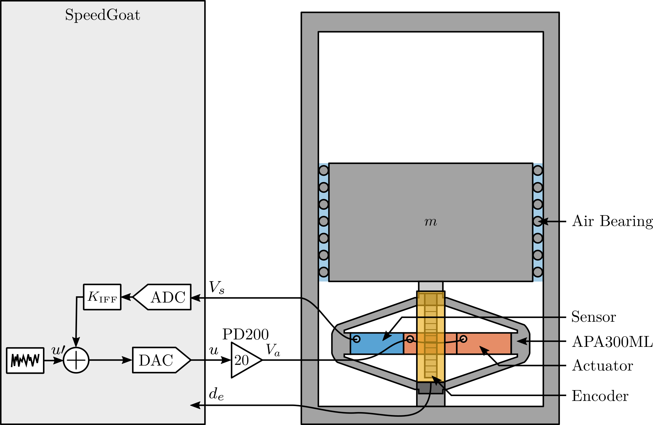
The identified dynamics were then fitted by second order transfer functions38. A comparison between the identified damped dynamics and the fitted second-order transfer functions is shown in Figure ref:fig:test_apa_identified_damped_plants for different gains $g$. It is clear that a large amount of damping is added when the gain is increased and that the frequency of the pole is shifted to lower frequencies.
The evolution of the pole in the complex plane as a function of the controller gain $g$ (i.e. the "root locus") is computed in two cases. First using the IFF plant model eqref:eq:test_apa_iff_manual_fit and the implemented controller eqref:eq:test_apa_Kiff_formula. Second using the fitted transfer functions of the damped plants experimentally identified for several controller gains. The two obtained root loci are compared in Figure ref:fig:test_apa_iff_root_locus and are in good agreement considering that the damped plants were fitted using only a second-order transfer function.
APA300ML - 2 degrees-of-freedom Model
<<sec:test_apa_model_2dof>>
Introduction
In this section, a multi-body model (Figure ref:fig:test_apa_bench_model) of the measurement bench is used to tune the two degrees-of-freedom model of the APA using the measured frequency response functions.
This two degrees-of-freedom model is developed to accurately represent the APA300ML dynamics while having low complexity and a low number of associated states. After the model is presented, the procedure for tuning the model is described, and the obtained model dynamics is compared with the measurements.
Two degrees-of-freedom APA Model
The model of the amplified piezoelectric actuator is shown in Figure ref:fig:test_apa_2dof_model. It can be decomposed into three components:
- the shell whose axial properties are represented by $k_1$ and $c_1$
- the actuator stacks whose contribution to the axial stiffness is represented by $k_a$ and $c_a$. The force source $f$ represents the axial force induced by the force sensor stacks. The sensitivity $g_a$ (in $N/m$) is used to convert the applied voltage $V_a$ to the axial force $f$
- the sensor stack whose contribution to the axial stiffness is represented by $k_e$ and $c_e$. A sensor measures the stack strain $d_e$ which is then converted to a voltage $V_s$ using a sensitivity $g_s$ (in $V/m$)
Such a simple model has some limitations:
- it only represents the axial characteristics of the APA as it is modeled as infinitely rigid in the other directions
- some physical insights are lost, such as the amplification factor and the real stress and strain in the piezoelectric stacks
- the creep and hysteresis of the piezoelectric stacks are not modeled as the model is linear
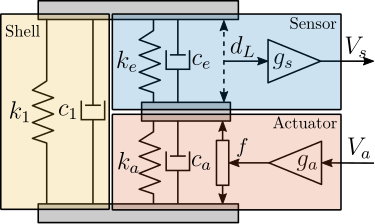
Tuning of the APA model
9 parameters ($m$, $k_1$, $c_1$, $k_e$, $c_e$, $k_a$, $c_a$, $g_s$ and $g_a$) have to be tuned such that the dynamics of the model (Figure ref:fig:test_apa_2dof_model_simscape) well represents the identified dynamics in Section ref:sec:test_apa_dynamics.
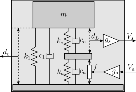
First, the mass $m$ supported by the APA300ML can be estimated from the geometry and density of the different parts or by directly measuring it using a precise weighing scale. Both methods lead to an estimated mass of $m = 5.7\,\text{kg}$.
Then, the axial stiffness of the shell was estimated at $k_1 = 0.38\,N/\mu m$ in Section ref:ssec:test_apa_meas_dynamics from the frequency of the anti-resonance seen on Figure ref:fig:test_apa_frf_force. Similarly, $c_1$ can be estimated from the damping ratio of the same anti-resonance and is found to be close to $5\,Ns/m$.
Then, it is reasonable to assume that the sensor stacks and the two actuator stacks have identical mechanical characteristics39. Therefore, we have $k_e = 2 k_a$ and $c_e = 2 c_a$ as the actuator stack is composed of two stacks in series. In this case, the total stiffness of the APA model is described by eqref:eq:test_apa_2dof_stiffness.
\begin{equation}\label{eq:test_apa_2dof_stiffness} k_{\text{tot}} = k_1 + \frac{k_e k_a}{k_e + k_a} = k_1 + \frac{2}{3} k_a
\end{equation}
Knowing from eqref:eq:test_apa_tot_stiffness that the total stiffness is $k_{\text{tot}} = 2\,N/\mu m$, we get from eqref:eq:test_apa_2dof_stiffness that $k_a = 2.5\,N/\mu m$ and $k_e = 5\,N/\mu m$.
\begin{equation}\label{eq:test_apa_tot_stiffness} ω_0 = \frac{k_{\text{tot}}}{m} \Longrightarrow k_{\text{tot}} = m ω_0^2 = 2\,N/μ m \quad \text{with}\ m = 5.7\,\text{kg}\ \text{and}\ ω_0 = 2π ⋅ 95\, \text{rad}/s
\end{equation}
Then, $c_a$ (and therefore $c_e = 2 c_a$) can be tuned to match the damping ratio of the identified resonance. $c_a = 50\,Ns/m$ and $c_e = 100\,Ns/m$ are obtained.
In the last step, $g_s$ and $g_a$ can be tuned to match the gain of the identified transfer functions.
The obtained parameters of the model shown in Figure ref:fig:test_apa_2dof_model_simscape are summarized in Table ref:tab:test_apa_2dof_parameters.
| Parameter | Value |
|---|---|
| $m$ | $5.7\,\text{kg}$ |
| $k_1$ | $0.38\,N/\mu m$ |
| $k_e$ | $5.0\, N/\mu m$ |
| $k_a$ | $2.5\,N/\mu m$ |
| $c_1$ | $5\,Ns/m$ |
| $c_e$ | $100\,Ns/m$ |
| $c_a$ | $50\,Ns/m$ |
| $g_a$ | $-2.58\,N/V$ |
| $g_s$ | $0.46\,V/\mu m$ |
Obtained Dynamics
The dynamics of the two degrees-of-freedom model of the APA300ML are extracted using optimized parameters (listed in Table ref:tab:test_apa_2dof_parameters) from the multi-body model. This is compared with the experimental data in Figure ref:fig:test_apa_2dof_comp_frf. A good match can be observed between the model and the experimental data, both for the encoder (Figure ref:fig:test_apa_2dof_comp_frf_enc) and for the force sensor (Figure ref:fig:test_apa_2dof_comp_frf_force). This indicates that this model represents well the axial dynamics of the APA300ML.
APA300ML - Super Element
<<sec:test_apa_model_flexible>>
Introduction
In this section, a super element of the APA300ML is computed using a finite element software40.
It is then imported into multi-body (in the form of a stiffness matrix and a mass matrix) and included in the same model that was used in ref:sec:test_apa_model_2dof.
This procedure is illustrated in Figure ref:fig:test_apa_super_element_simscape.
Several remote points are defined in the finite element model (here illustrated by colorful planes and numbers from 1 to 5) and are then made accessible in Simscape as shown at the right by the "frames" F1 to F5.
For the APA300ML super element, 5 remote points are defined.
Two remote points (1 and 2) are fixed to the top and bottom mechanical interfaces of the APA300ML and will be used to connect the APA300ML with other mechanical elements.
Two remote points (3 and 4) are located across two piezoelectric stacks and are used to apply internal forces representing the actuator stacks.
Finally, two remote points (4 and 5) are located across the third piezoelectric stack, and will be used to measured the strain of the sensor stack.
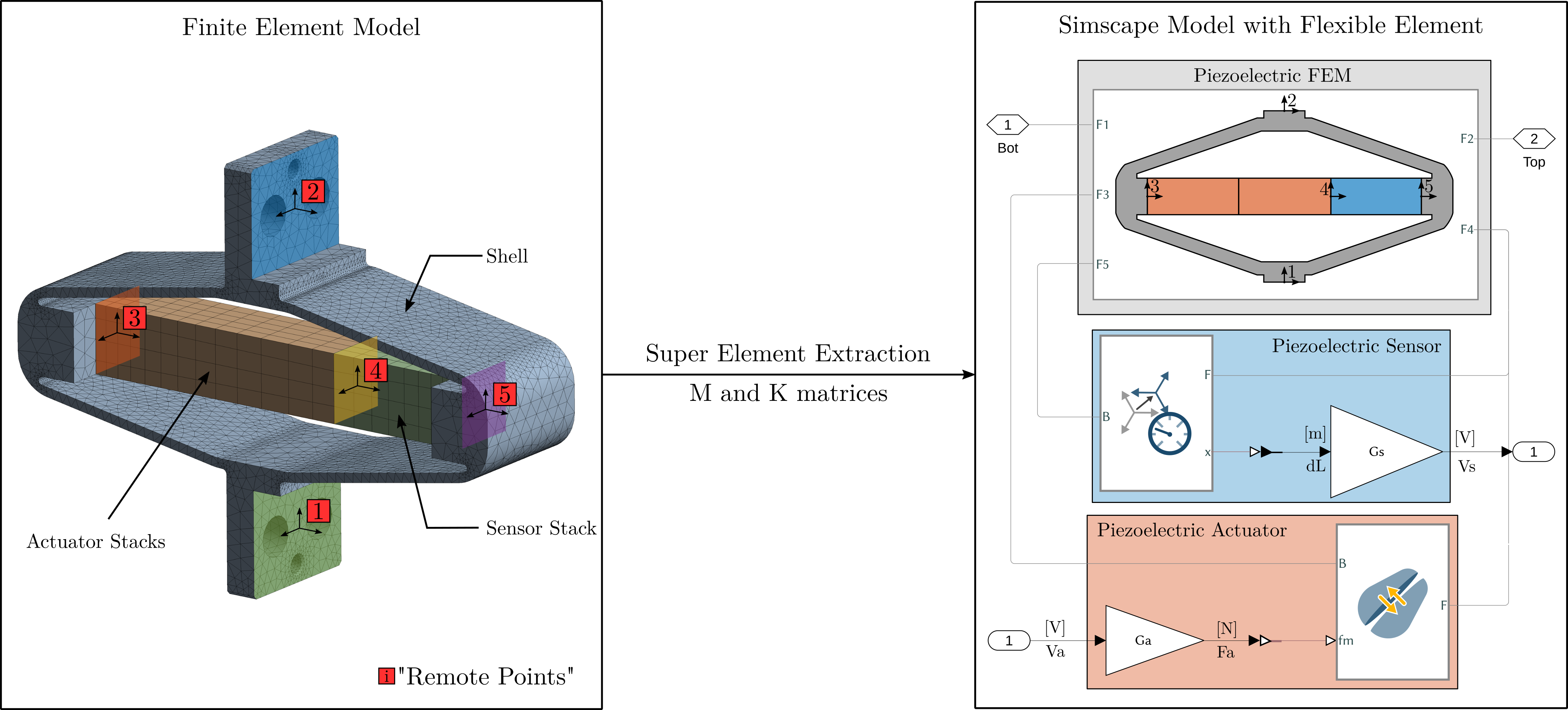
Identification of the Actuator and Sensor constants
Once the APA300ML super element is included in the multi-body model, the transfer function from $F_a$ to $d_L$ and $d_e$ can be extracted. The gains $g_a$ and $g_s$ are then tuned such that the gains of the transfer functions match the identified ones. By doing so, $g_s = 4.9\,V/\mu m$ and $g_a = 23.2\,N/V$ are obtained.
To ensure that the sensitivities $g_a$ and $g_s$ are physically valid, it is possible to estimate them from the physical properties of the piezoelectric stack material.
From cite:&fleming14_desig_model_contr_nanop_system p. 123, the relation between relative displacement $d_L$ of the sensor stack and generated voltage $V_s$ is given by eqref:eq:test_apa_piezo_strain_to_voltage and from cite:&fleming10_integ_strain_force_feedb_high the relation between the force $F_a$ and the applied voltage $V_a$ is given by eqref:eq:test_apa_piezo_voltage_to_force.
\begin{subequations} \begin{align} V_s &= \underbrace{\frac{d_{33}}{\epsilon^T s^D n}}_{g_s} d_L \label{eq:test_apa_piezo_strain_to_voltage} \\ F_a &= \underbrace{d_{33} n k_a}_{g_a} \cdot V_a, \quad k_a = \frac{c^{E} A}{L} \label{eq:test_apa_piezo_voltage_to_force} \end{align} \end{subequations}Unfortunately, the manufacturer of the stack was not willing to share the piezoelectric material properties of the stack used in the APA300ML. However, based on the available properties of the APA300ML stacks in the data-sheet, the soft Lead Zirconate Titanate "THP5H" from Thorlabs seemed to match quite well the observed properties. The properties of this "THP5H" material used to compute $g_a$ and $g_s$ are listed in Table ref:tab:test_apa_piezo_properties.
From these parameters, $g_s = 5.1\,V/\mu m$ and $g_a = 26\,N/V$ were obtained, which are close to the constants identified using the experimentally identified transfer functions.
| Parameter | Value | Description |
|---|---|---|
| $d_{33}$ | $680 \cdot 10^{-12}\,m/V$ | Piezoelectric constant |
| $\epsilon^{T}$ | $4.0 \cdot 10^{-8}\,F/m$ | Permittivity under constant stress |
| $s^{D}$ | $21 \cdot 10^{-12}\,m^2/N$ | Elastic compliance understand constant electric displacement |
| $c^{E}$ | $48 \cdot 10^{9}\,N/m^2$ | Young's modulus of elasticity |
| $L$ | $20\,mm$ per stack | Length of the stack |
| $A$ | $10^{-4}\,m^2$ | Area of the piezoelectric stack |
| $n$ | $160$ per stack | Number of layers in the piezoelectric stack |
Comparison of the obtained dynamics
The obtained dynamics using the super element with the tuned "sensor sensitivity" and "actuator sensitivity" are compared with the experimentally identified frequency response functions in Figure ref:fig:test_apa_super_element_comp_frf. A good match between the model and the experimental results was observed. It is however surprising that the model is "softer" than the measured system, as finite element models usually overestimate the stiffness (see Section ref:ssec:test_apa_spurious_resonances for possible explanations).
Using this simple test bench, it can be concluded that the super element model of the APA300ML captures the axial dynamics of the actuator (the actuator stacks, the force sensor stack as well as the shell used as a mechanical lever).
Conclusion
<<sec:test_apa_conclusion>>
In this study, the amplified piezoelectric actuators "APA300ML" have been characterized to ensure that they fulfill all the requirements determined during the detailed design phase.
Geometrical features such as the flatness of its interfaces, electrical capacitance, and achievable strokes were measured in Section ref:sec:test_apa_basic_meas. These simple measurements allowed for the early detection of a manufacturing defect in one of the APA300ML.
Then in Section ref:sec:test_apa_dynamics, using a dedicated test bench, the dynamics of all the APA300ML were measured and were found to all match very well (Figure ref:fig:test_apa_frf_dynamics). This consistency indicates good manufacturing tolerances, facilitating the modeling and control of the nano-hexapod. Although a non-minimum zero was identified in the transfer function from $u$ to $V_s$ (Figure ref:fig:test_apa_non_minimum_phase), it was found not to be problematic because a large amount of damping could be added using the integral force feedback strategy (Figure ref:fig:test_apa_iff).
Then, two different models were used to represent the APA300ML dynamics. In Section ref:sec:test_apa_model_2dof, a simple two degrees-of-freedom mass-spring-damper model was presented and tuned based on the measured dynamics. After following a tuning procedure, the model dynamics was shown to match very well with the experiment. However, this model only represents the axial dynamics of the actuators, assuming infinite stiffness in other directions.
In Section ref:sec:test_apa_model_flexible, a super element extracted from a finite element model was used to model the APA300ML. Here, the super element represents the dynamics of the APA300ML in all directions. However, only the axial dynamics could be compared with the experimental results, yielding a good match. The benefit of employing this model over the two degrees-of-freedom model is not immediately apparent due to its increased complexity and the larger number of model states involved. Nonetheless, the super element model's value will become clear in subsequent sections, when its capacity to accurately model the APA300ML's flexibility across various directions will be important.
Flexible Joints
<<sec:test_joints>>
Introduction
At both ends of the nano-hexapod struts, a flexible joint is used. Ideally, these flexible joints would behave as perfect spherical joints, that is to say no bending and torsional stiffness, infinite shear and axial stiffness, unlimited bending and torsional stroke, no friction, and no backlash.
Deviations from these ideal properties will impact the dynamics of the Nano-Hexapod and could limit the attainable performance. During the detailed design phase, specifications in terms of stiffness and stroke were determined and are summarized in Table ref:tab:test_joints_specs.
| Specification | FEM | |
|---|---|---|
| Axial Stiffness | $> 100\,N/\mu m$ | 94 |
| Shear Stiffness | $> 1\,N/\mu m$ | 13 |
| Bending Stiffness | $< 100\,Nm/\text{rad}$ | 5 |
| Torsion Stiffness | $< 500\,Nm/\text{rad}$ | 260 |
| Bending Stroke | $> 1\,\text{mrad}$ | 24.5 |
After optimization using a finite element model, the geometry shown in Figure ref:fig:test_joints_schematic has been obtained and the corresponding flexible joint characteristics are summarized in Table ref:tab:test_joints_specs. This flexible joint is a monolithic piece of stainless steel41 manufactured using wire electrical discharge machining. It serves several functions, as shown in Figure ref:fig:test_joints_iso, such as:
- Rigid interfacing with the nano-hexapod plates (yellow surfaces)
- Rigid interfacing with the amplified piezoelectric actuator (blue surface)
- Allow two rotations between the "yellow" and the "blue" interfaces. The rotation axes are represented by the dashed lines that intersect
Sixteen flexible joints have been ordered (shown in Figure ref:fig:test_joints_received) such that some selection can be made for the twelve that will be used on the nano-hexapod.
In this document, the received flexible joints are characterized to ensure that they fulfill the requirements and such that they can well be modeled.
First, the flexible joints are visually inspected, and the minimum gaps (responsible for most of the joint compliance) are measured (Section ref:sec:test_joints_flex_dim_meas). Then, a test bench was developed to measure the bending stiffness of the flexible joints. The development of this test bench is presented in Section ref:sec:test_joints_test_bench_desc, including a noise budget and some requirements in terms of instrumentation. The test bench is then used to measure the bending stiffnesses of all the flexible joints. Results are shown in Section ref:sec:test_joints_bending_stiffness_meas
Dimensional Measurements
<<sec:test_joints_flex_dim_meas>>
Measurement Bench
Two dimensions are critical for the bending stiffness of the flexible joints. These dimensions can be measured using a profilometer. The dimensions of the flexible joint in the Y-Z plane will contribute to the X-bending stiffness, whereas the dimensions in the X-Z plane will contribute to the Y-bending stiffness.
The setup used to measure the dimensions of the "X" flexible beam is shown in Figure ref:fig:test_joints_profilometer_setup. What is typically observed is shown in Figure ref:fig:test_joints_profilometer_image. It is then possible to estimate the dimension of the flexible beam with an accuracy of $\approx 5\,\mu m$,
Measurement Results
The specified flexible beam thickness (gap) is $250\,\mu m$. Four gaps are measured for each flexible joint (2 in the $x$ direction and 2 in the $y$ direction). The "beam thickness" is then estimated as the mean between the gaps measured on opposite sides.
A histogram of the measured beam thicknesses is shown in Figure ref:fig:test_joints_size_hist. The measured thickness is less than the specified value of $250\,\mu m$, but this optical method may not be very accurate because the estimated gap can depend on the lighting of the part and of its proper alignment.
However, what is more important than the true value of the thickness is the consistency between all flexible joints.
Compliance Measurement Test Bench
<<sec:test_joints_test_bench_desc>>
Introduction
The most important characteristic of the flexible joint to be measured is its bending stiffness $k_{R_x} \approx k_{R_y}$.
To estimate the bending stiffness, the basic idea is to apply a torque $T_{x}$ to the flexible joints and to measure its angular deflection $\theta_{x}$. The bending stiffness can then be computed from equation eqref:eq:test_joints_bending_stiffness.
\begin{equation}\label{eq:test_joints_bending_stiffness} \boxed{kR_x = \frac{T_x}{θ_x}, \quad kR_y = \frac{T_y}{θ_y}}
\end{equation}
Measurement principle
<<ssec:test_joints_meas_principle>>
Torque and Rotation measurement
To apply torque $T_{y}$ between the two mobile parts of the flexible joint, a known "linear" force $F_{x}$ can be applied instead at a certain distance $h$ with respect to the rotation point. In this case, the equivalent applied torque can be estimated from equation eqref:eq:test_joints_force_torque_distance. Note that the application point of the force should be sufficiently far from the rotation axis such that the resulting bending motion is much larger than the displacement due to shear. Such effects are studied in Section ref:ssec:test_joints_error_budget.
\begin{equation}\label{eq:test_joints_force_torque_distance} T_y = h F_x, \quad T_x = h F_y
\end{equation}
Similarly, instead of directly measuring the bending motion $\theta_y$ of the flexible joint, its linear motion $d_x$ at a certain distance $h$ from the rotation points is measured. The equivalent rotation is estimated from eqref:eq:test_joints_rot_displ.
\begin{equation}\label{eq:test_joints_rot_displ} θ_y = tan-1≤ft(\frac{d_x}{h}\right) ≈ \frac{d_x}{h}, \quad θ_x = tan-1 ≤ft( \frac{d_y}{h} \right) ≈ \frac{d_y}{h}
\end{equation}
Then, the bending stiffness can be estimated from eqref:eq:test_joints_stiff_displ_force.
\begin{subequations}\label{eq:test_joints_stiff_displ_force}
\begin{align} k_{R_x} &= \frac{T_x}{\theta_x} = \frac{h F_y}{\tan^{-1}\left( \frac{d_y}{h} \right)} \approx h^2 \frac{F_y}{d_y} \\ k_{R_y} &= \frac{T_y}{\theta_y} = \frac{h F_x}{\tan^{-1}\left( \frac{d_x}{h} \right)} \approx h^2 \frac{F_x}{d_x} \end{align}\end{subequations}
The working principle of the measurement bench is schematically shown in Figure ref:fig:test_joints_bench_working_principle. One part of the flexible joint is fixed to a rigid frame while a (known) force $F_x$ is applied to the other side of the flexible joint. The deflection of the joint $d_x$ is measured using a displacement sensor.
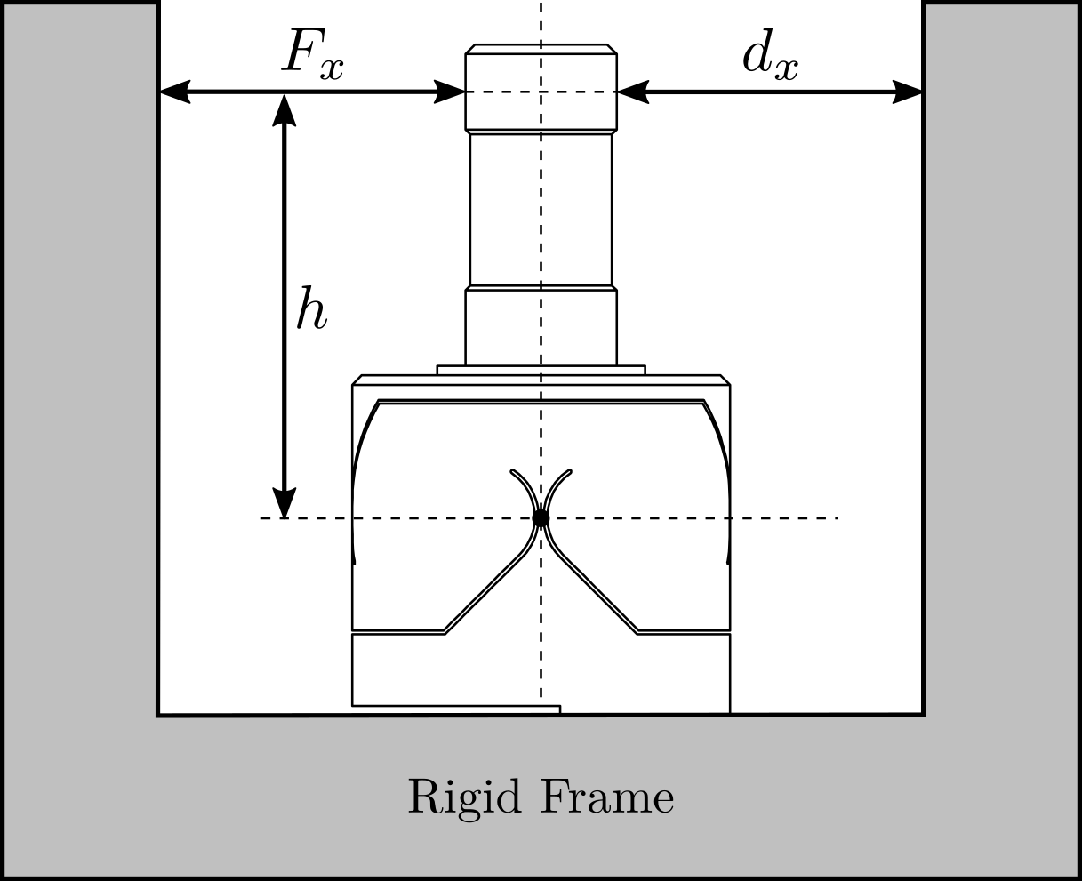
Required external applied force
The bending stiffness is foreseen to be $k_{R_y} \approx k_{R_x} \approx 5\,\frac{Nm}{rad}$ and its stroke $\theta_{y,\text{max}}\approx \theta_{x,\text{max}}\approx 25\,mrad$. The height between the flexible point (center of the joint) and the point where external forces are applied is $h = 22.5\,mm$ (see Figure ref:fig:test_joints_bench_working_principle).
The bending $\theta_y$ of the flexible joint due to the force $F_x$ is given by equation eqref:eq:test_joints_deflection_force.
\begin{equation}\label{eq:test_joints_deflection_force} θ_y = \frac{T_y}{kR_y} = \frac{F_x h}{kR_y}
\end{equation}
Therefore, the force that must be applied to test the full range of the flexible joints is given by equation eqref:eq:test_joints_max_force. The measurement range of the force sensor should then be higher than $5.5\,N$.
\begin{equation}\label{eq:test_joints_max_force} F_{x,\text{max}} = \frac{kR_y θ_{y,\text{max}}}{h} ≈ 5.5\,N
\end{equation}
Required actuator stroke and sensors range
The flexible joint is designed to allow a bending motion of $\pm 25\,mrad$. The corresponding stroke at the location of the force sensor is given by eqref:eq:test_joints_max_stroke. To test the full range of the flexible joint, the means of applying a force (explained in the next section) should allow a motion of at least $0.5\,mm$. Similarly, the measurement range of the displacement sensor should also be higher than $0.5\,mm$.
\begin{equation}\label{eq:test_joints_max_stroke} d_{x,\text{max}} = h tan(R_{x,\text{max}}) ≈ 0.5\,mm
\end{equation}
Force and Displacement measurements
To determine the applied force, a load cell will be used in series with the mechanism that applied the force. The measured deflection of the flexible joint will be indirectly estimated from the displacement of the force sensor itself (see Section ref:ssec:test_joints_test_bench). Indirectly measuring the deflection of the flexible joint induces some errors because of the limited stiffness between the force sensor and the displacement sensor. Such an effect will be estimated in the error budget (Section ref:ssec:test_joints_error_budget)
Error budget
<<ssec:test_joints_error_budget>>
Introduction
To estimate the accuracy of the measured bending stiffness that can be obtained using this measurement principle, an error budget is performed.
Based on equation eqref:eq:test_joints_stiff_displ_force, several errors can affect the accuracy of the measured bending stiffness:
- Errors in the measured torque $M_x, M_y$: this is mainly due to inaccuracies in the load cell and of the height estimation $h$
- Errors in the measured bending motion of the flexible joints $\theta_x, \theta_y$: errors from limited shear stiffness, from the deflection of the load cell itself, and inaccuracy of the height estimation $h$
If only the bending stiffness is considered, the induced displacement is described by eqref:eq:test_joints_dbx.
\begin{equation}\label{eq:test_joints_dbx} dx,b = h tan(θ_y) = h tan≤ft( \frac{F_x ⋅ h}{kR_y} \right)
\end{equation}
Effect of Shear
The applied force $F_x$ will induce some shear $d_{x,s}$ which is described by eqref:eq:test_joints_shear_displ with $k_s$ the shear stiffness of the flexible joint.
\begin{equation}\label{eq:test_joints_shear_displ} dx,s = \frac{F_x}{k_s}
\end{equation}
The measured displacement $d_x$ is affected shear, as shown in equation eqref:eq:test_joints_displ_shear.
\begin{equation}\label{eq:test_joints_displ_shear} d_x = dx,b + dx,s = h tan≤ft( \frac{F_x ⋅ h}{kR_y} \right) + \frac{F_x}{k_s} ≈ F_x ≤ft( \frac{h^2}{kR_y} + \frac{1}{k_s} \right)
\end{equation}
The estimated bending stiffness $k_{\text{est}}$ then depends on the shear stiffness eqref:eq:test_joints_error_shear.
\begin{equation}\label{eq:test_joints_error_shear} k_{R_y,\text{est}} = h^2 \frac{F_x}{d_x} ≈ kR_y \frac{1}{1 + \frac{kR_y}{k_s h^2}} ≈ kR_y \Bigl( 1 - _brace{\frac{kR_y}{k_s h^2}}_{εs} \Bigl)
\end{equation}
With an estimated shear stiffness $k_s = 13\,N/\mu m$ from the finite element model and an height $h=25\,mm$, the estimation errors of the bending stiffness due to shear is $\epsilon_s < 0.1\,\%$
Effect of load cell limited stiffness
As explained in the previous section, because the measurement of the flexible joint deflection is indirectly performed with the encoder, errors will be made if the load cell experiences some compression.
Suppose the load cell has an internal stiffness $k_f$, the same reasoning that was made for the effect of shear can be applied here. The estimation error of the bending stiffness due to the limited stiffness of the load cell is then described by eqref:eq:test_joints_error_load_cell_stiffness.
\begin{equation}\label{eq:test_joints_error_load_cell_stiffness} k_{R_y,\text{est}} = h^2 \frac{F_x}{d_x} ≈ kR_y \frac{1}{1 + \frac{kR_y}{k_F h^2}} ≈ kR_y \Bigl( 1 - _brace{\frac{kR_y}{k_F h^2}}ε_f \Bigl)
\end{equation}
With an estimated load cell stiffness of $k_f \approx 1\,N/\mu m$ (from the documentation), the errors due to the load cell limited stiffness is around $\epsilon_f = 1\,\%$.
Estimation error due to height estimation error
Now consider an error $\delta h$ in the estimation of the height $h$ as described by eqref:eq:test_joints_est_h_error.
\begin{equation}\label{eq:test_joints_est_h_error} h_{\text{est}} = h + δ h
\end{equation}
The computed bending stiffness will be eqref:eq:test_joints_stiffness_height_error.
\begin{equation}\label{eq:test_joints_stiffness_height_error} k_{R_y, \text{est}} ≈ h_{\text{est}}^2 \frac{F_x}{d_x} ≈ kR_y \Bigl( 1 + _brace{2 \frac{δ h}{h} + \frac{δ h ^2}{h^2}}ε_h \Bigl)
\end{equation}
The height estimation is foreseen to be accurate to within $|\delta h| < 0.4\,mm$ which corresponds to a stiffness error $\epsilon_h < 3.5\,\%$.
Estimation error due to force and displacement sensors accuracy
An optical encoder is used to measure the displacement (see Section ref:ssec:test_joints_test_bench) whose maximum non-linearity is $40\,nm$. As the measured displacement is foreseen to be $0.5\,mm$, the error $\epsilon_d$ due to the encoder non-linearity is negligible $\epsilon_d < 0.01\,\%$.
The accuracy of the load cell is specified at $1\,\%$ and therefore, estimation errors of the bending stiffness due to the limited load cell accuracy should be $\epsilon_F < 1\,\%$
Conclusion
The different sources of errors are summarized in Table ref:tab:test_joints_error_budget. The most important source of error is the estimation error of the distance between the flexible joint rotation axis and its contact with the force sensor. An overall accuracy of $\approx 5\,\%$ can be expected with this measurement bench, which should be sufficient for an estimation of the bending stiffness of the flexible joints.
| Effect | Error |
|---|---|
| Shear effect | $\epsilon_s < 0.1\,\%$ |
| Load cell compliance | $\epsilon_f = 1\,\%$ |
| Height error | $\epsilon_h < 3.5\,\%$ |
| Displacement sensor | $\epsilon_d < 0.01\,\%$ |
| Force sensor | $\epsilon_F < 1\,\%$ |
Mechanical Design
<<ssec:test_joints_test_bench>>
As explained in Section ref:ssec:test_joints_meas_principle, the flexible joint's bending stiffness is estimated by applying a known force to the flexible joint's tip and by measuring its deflection at the same point.
The force is applied using a load cell42 such that the applied force to the flexible joint's tip is directly measured. To control the height and direction of the applied force, a cylinder cut in half is fixed at the tip of the force sensor (pink element in Figure ref:fig:test_joints_bench_side) that initially had a flat surface. Doing so, the contact between the flexible joint cylindrical tip and the force sensor is a point (intersection of two cylinders) at a precise height, and the force is applied in a known direction. To translate the load cell at a constant height, it is fixed to a translation stage43 which is moved by hand.
Instead of measuring the displacement directly at the tip of the flexible joint (with a probe or an interferometer for instance), the displacement of the load cell itself is measured. To do so, an encoder44 is used, which measures the motion of a ruler. This ruler is fixed to the translation stage in line (i.e. at the same height) with the application point to reduce Abbe errors (see Figure ref:fig:test_joints_bench_overview).
The flexible joint can be rotated by $90^o$ in order to measure the bending stiffness in the two directions. The obtained CAD design of the measurement bench is shown in Figure ref:fig:test_joints_bench_overview while a zoom on the flexible joint with the associated important quantities is shown in Figure ref:fig:test_joints_bench_side.
Bending Stiffness Measurement
<<sec:test_joints_bending_stiffness_meas>>
Introduction
Load Cell Calibration
In order to estimate the measured errors of the load cell "FC2231", it is compared against another load cell45. The two load cells are measured simultaneously while they are pushed against each other (see Figure ref:fig:test_joints_force_sensor_calib_picture). The contact between the two load cells is well defined as one has a spherical interface and the other has a flat surface.
The measured forces are compared in Figure ref:fig:test_joints_force_sensor_calib_fit. The gain mismatch between the two load cells is approximately $4\,\%$ which is higher than that specified in the data sheets. However, the estimated non-linearity is bellow $0.2\,\%$ for forces between $1\,N$ and $5\,N$.
Load Cell Stiffness
The objective of this measurement is to estimate the stiffness $k_F$ of the force sensor. To do so, a stiff element (much stiffer than the estimated $k_F \approx 1\,N/\mu m$) is mounted in front of the force sensor, as shown in Figure ref:fig:test_joints_meas_force_sensor_stiffness_picture. Then, the force sensor is pushed against this stiff element while the force sensor and the encoder displacement are measured. The measured displacement as a function of the measured force is shown in Figure ref:fig:test_joints_force_sensor_stiffness_fit. The load cell stiffness can then be estimated by computing a linear fit and is found to be $k_F \approx 0.68\,N/\mu m$.
Bending Stiffness estimation
The actual stiffness is now estimated by manually moving the translation stage from a start position where the force sensor is not yet in contact with the flexible joint to a position where the flexible joint is on its mechanical stop.
The measured force and displacement as a function of time are shown in Figure ref:fig:test_joints_meas_bend_time. Three regions can be observed: first, the force sensor tip is not in contact with the flexible joint and the measured force is zero; then, the flexible joint deforms linearly; and finally, the flexible joint comes in contact with the mechanical stop.
The angular motion $\theta_{y}$ computed from the displacement $d_x$ is displayed as function of the measured torque $T_{y}$ in Figure ref:fig:test_joints_meas_F_d_lin_fit. The bending stiffness of the flexible joint can be estimated by computing the slope of the curve in the linear regime (red dashed line) and is found to be $k_{R_y} = 4.4\,Nm/\text{rad}$. The bending stroke can also be estimated as shown in Figure ref:fig:test_joints_meas_F_d_lin_fit and is found to be $\theta_{y,\text{max}} = 20.9\,\text{mrad}$.
Measured flexible joint stiffness
The same measurement was performed for all the 16 flexible joints, both in the $x$ and $y$ directions. The measured angular motion as a function of the applied torque is shown in Figure ref:fig:test_joints_meas_bending_all_raw_data for the 16 flexible joints. This gives a first idea of the dispersion of the measured bending stiffnesses (i.e. slope of the linear region) and of the angular stroke.
A histogram of the measured bending stiffnesses is shown in Figure ref:fig:test_joints_bend_stiff_hist. Most of the bending stiffnesses are between $4.6\,Nm/rad$ and $5.0\,Nm/rad$.
Conclusion
<<sec:test_joints_conclusion>>
The flexible joints are a key element of the nano-hexapod. Careful dimensional measurements (Section ref:sec:test_joints_flex_dim_meas) allowed for the early identification of faulty flexible joints. This was crucial in preventing potential complications that could have arisen from the installation of faulty joints on the nano-hexapod.
A dedicated test bench was developed to asses the bending stiffness of the flexible joints. Through meticulous error analysis and budgeting, a satisfactory level of measurement accuracy could be guaranteed. The measured bending stiffness values exhibited good agreement with the predictions from the finite element model ($k_{R_x} = k_{R_y} = 5\,Nm/\text{rad}$). These measurements are helpful for refining the model of the flexible joints, thereby enhancing the overall accuracy of the nano-hexapod model. Furthermore, the data obtained from these measurements have provided the necessary information to select the most suitable flexible joints for the nano-hexapod, ensuring optimal performance.
Struts
<<sec:test_struts>>
Introduction
The Nano-Hexapod struts (shown in Figure ref:fig:test_struts_picture_strut) are composed of two flexible joints that are fixed at the two ends of the strut, one Amplified Piezoelectric Actuator46 and one optical encoder47.
After the strut elements have been individually characterized (see previous sections), the struts are assembled. The mounting procedure of the struts is explained in Section ref:sec:test_struts_mounting. A mounting bench was used to ensure coaxiality between the two ends of the struts. In this way, no angular stroke is lost when mounted to the nano-hexapod.
The flexible modes of the struts were then experimentally measured and compared with a finite element model (Section ref:sec:test_struts_flexible_modes).
Dynamic measurements of the strut are performed with the same test bench used to characterize the APA300ML dynamics (Section ref:sec:test_struts_dynamical_meas). It was found that the dynamics from the acrshort:dac voltage to the displacement measured by the encoder is complex due to the flexible modes of the struts (Section ref:sec:test_struts_flexible_modes).
The strut models were then compared with the measured dynamics (Section ref:sec:test_struts_simscape). The model dynamics from the acrshort:dac voltage to the axial motion of the strut (measured by an interferometer) and to the force sensor voltage well match the experimental results. However, this is not the case for the dynamics from acrshort:dac voltage to the encoder displacement. It is found that the complex dynamics is due to a misalignment between the flexible joints and the acrshort:apa.
Mounting Procedure
<<sec:test_struts_mounting>>
A mounting bench was developed to ensure:
- Good coaxial alignment between the interfaces (cylinders) of the flexible joints. This is important not to loose to much angular stroke during their mounting into the nano-hexapod
- Uniform length across all struts
- Precise alignment of the APA with the two flexible joints
- Reproducible and consistent assembly between all struts
A CAD view of the mounting bench is shown in Figure ref:fig:test_struts_mounting_bench_first_concept. It consists of a "main frame" (Figure ref:fig:test_struts_mounting_step_0) precisely machined to ensure both correct strut length and strut coaxiality. The coaxiality is ensured by good flatness (specified at $20\,\mu m$) between surfaces A and B and between surfaces C and D. Such flatness was checked using a FARO arm48 (see Figure ref:fig:test_struts_check_dimensions_bench) and was found to comply with the requirements. The strut length (defined by the distance between the rotation points of the two flexible joints) was ensured by using precisely machined dowel holes.
The flexible joints were not directly fixed to the mounting bench but were fixed to a cylindrical "sleeve" shown in Figures ref:fig:test_struts_cylindrical_mounting_part_top and ref:fig:test_struts_cylindrical_mounting_part_bot. The goal of these "sleeves" is to avoid mechanical stress that could damage the flexible joints during the mounting process. These "sleeves" have one dowel groove (that are fitted to the dowel holes shown in Figure ref:fig:test_struts_mounting_step_0) that will determine the length of the mounted strut.
The "sleeves" were mounted to the main element as shown in Figure ref:fig:test_struts_mounting_step_0. The left sleeve has a thigh fit such that its orientation is fixed (it is roughly aligned horizontally), while the right sleeve has a loose fit such that it can rotate (it will get the same orientation as the fixed one when tightening the screws).
The cylindrical washers and the APA300ML are stacked on top of the flexible joints, as shown in Figure ref:fig:test_struts_mounting_step_2 and screwed together using a torque screwdriver. A dowel pin is used to laterally align the APA300ML with the flexible joints (see the dowel slot on the flexible joints in Figure ref:fig:test_struts_mounting_joints). Two cylindrical washers are used to allow proper mounting even when the two APA interfaces are not parallel.
The encoder and ruler are then fixed to the strut and properly aligned, as shown in Figure ref:fig:test_struts_mounting_step_3.
Finally, the strut can be disassembled from the mounting bench (Figure ref:fig:test_struts_mounting_step_4). Thanks to this mounting procedure, the coaxiality and length between the two flexible joint's interfaces can be obtained within the desired tolerances.
Measurement of flexible modes
<<sec:test_struts_flexible_modes>>
A Finite Element Model49 of the struts is developed and is used to estimate the flexible modes. The inertia of the encoder (estimated at $15\,g$) is considered. The two cylindrical interfaces were fixed (boundary conditions), and the first three flexible modes were computed. The mode shapes are displayed in Figure ref:fig:test_struts_mode_shapes: an "X-bending" mode at 189Hz, a "Y-bending" mode at 285Hz and a "Z-torsion" mode at 400Hz.
To experimentally measure these mode shapes, a Laser vibrometer50 was used. It measures the difference of motion between two beam path (red points in Figure ref:fig:test_struts_meas_modes). The strut is then excited by an instrumented hammer, and the transfer function from the hammer to the measured rotation is computed.
The setup used to measure the "X-bending" mode is shown in Figure ref:fig:test_struts_meas_x_bending. The "Y-bending" mode is measured as shown in Figure ref:fig:test_struts_meas_y_bending and the "Z-torsion" measurement setup is shown in Figure ref:fig:test_struts_meas_z_torsion. These tests were performed with and without the encoder being fixed to the strut.
The obtained frequency response functions for the three configurations (X-bending, Y-bending and Z-torsion) are shown in Figure ref:fig:test_struts_spur_res_frf_no_enc when the encoder is not fixed to the strut and in Figure ref:fig:test_struts_spur_res_frf_enc when the encoder is fixed to the strut.
Table ref:tab:test_struts_spur_mode_freqs summarizes the measured resonance frequencies and the computed ones using the acrfull:fem. The resonance frequencies of the 3 modes are only slightly decreased when the encoder is fixed to the strut. In addition, the computed resonance frequencies from the acrshort:fem are very close to the measured frequencies when the encoder is fixed to the strut. This validates the quality of the acrshort:fem.
| Mode | FEM with Encoder | Exp. with Encoder | Exp. without Encoder |
|---|---|---|---|
| X-Bending | 189Hz | 198Hz | 226Hz |
| Y-Bending | 285Hz | 293Hz | 337Hz |
| Z-Torsion | 400Hz | 381Hz | 398Hz |
Dynamical measurements
<<sec:test_struts_dynamical_meas>>
Introduction
In order to measure the dynamics of the strut, the test bench used to measure the APA300ML dynamics is being used again.
The strut mounted on the bench is shown in Figure ref:fig:test_struts_bench_leg_overview A schematic of the bench and the associated signals are shown in Figure ref:fig:test_struts_bench_schematic. A fiber interferometer51 is used to measure the motion of the granite (i.e. the axial motion of the strut).
First, the effect of the encoder on the measured dynamics is investigated in Section ref:ssec:test_struts_effect_encoder. The dynamics observed by the encoder and interferometers are compared in Section ref:ssec:test_struts_comp_enc_int. Finally, all measured struts are compared in terms of dynamics in Section ref:ssec:test_struts_comp_all_struts.
Effect of the Encoder on the measured dynamics
<<ssec:test_struts_effect_encoder>>
System identification was performed without the encoder being fixed to the strut (Figure ref:fig:test_struts_bench_leg_front) and with one encoder being fixed to the strut (Figure ref:fig:test_struts_bench_leg_coder).
The obtained frequency response functions are compared in Figure ref:fig:test_struts_effect_encoder. It was found that the encoder had very little effect on the transfer function from excitation voltage $u$ to the axial motion of the strut $d_a$ as measured by the interferometer (Figure ref:fig:test_struts_effect_encoder_int). This means that the axial motion of the strut is unaffected by the presence of the encoder. Similarly, it has little effect on the transfer function from $u$ to the sensor stack voltage $V_s$ (Figure ref:fig:test_struts_effect_encoder_iff). This means that the encoder should have little effect on the effectiveness of the integral force feedback control strategy.
Comparison of the encoder and interferometer
<<ssec:test_struts_comp_enc_int>>
The dynamics measured by the encoder (i.e. $d_e/u$) and interferometers (i.e. $d_a/u$) are compared in Figure ref:fig:test_struts_comp_enc_int. The dynamics from the excitation voltage $u$ to the displacement measured by the encoder $d_e$ presents a behavior that is much more complex than the dynamics of the displacement measured by the interferometer (comparison made in Figure ref:fig:test_struts_comp_enc_int). Three additional resonance frequencies can be observed at 197Hz, 290Hz and 376Hz. These resonance frequencies match the frequencies of the flexible modes studied in Section ref:sec:test_struts_flexible_modes.
The good news is that these resonances are not impacting the axial motion of the strut (which is what is important for the hexapod positioning). However, these resonances make the use of an encoder fixed to the strut difficult from a control perspective.
Comparison of all the Struts
<<ssec:test_struts_comp_all_struts>>
The dynamics of all the mounted struts (only 5 at the time of the experiment) were then measured on the same test bench. The obtained dynamics from $u$ to $d_a$ are compared in Figure ref:fig:test_struts_comp_interf_plants while is dynamics from $u$ to $V_s$ are compared in Figure ref:fig:test_struts_comp_iff_plants. A very good match can be observed between the struts.
The same comparison is made for the transfer function from $u$ to $d_e$ (encoder output) in Figure ref:fig:test_struts_comp_enc_plants. In this study, large dynamics differences were observed between the 5 struts. Although the same resonance frequencies were seen for all of the struts (95Hz, 200Hz, 300Hz and 400Hz), the amplitude of the peaks were not the same. In addition, the location or even presence of complex conjugate zeros changes from one strut to another. The reason for this variability will be studied in the next section thanks to the strut model.
Strut Model
<<sec:test_struts_simscape>>
Introduction
The multi-body model of the strut was included in the multi-body model of the test bench (see Figure ref:fig:test_struts_simscape_model). The obtained model was first used to compare the measured FRF with the existing model (Section ref:ssec:test_struts_comp_model).
Using a flexible APA model (extracted from a acrshort:fem), the effect of a misalignment of the APA with respect to flexible joints is studied (Section ref:ssec:test_struts_effect_misalignment). It was found that misalignment has a large impact on the dynamics from $u$ to $d_e$. This misalignment is estimated and measured in Section ref:ssec:test_struts_meas_misalignment. The struts were then disassembled and reassemble a second time to optimize alignment (Section ref:sec:test_struts_meas_all_aligned_struts).
Model dynamics
<<ssec:test_struts_comp_model>>
Two models of the APA300ML are used here: a simple two-degrees-of-freedom model and a model using a super-element extracted from a acrlong:fem. These two models of the APA300ML were tuned to best match the measured frequency response functions of the APA alone. The flexible joints were modelled with the 4DoF model (axial stiffness, two bending stiffnesses and one torsion stiffness). These two models are compared with the measured frequency responses in Figure ref:fig:test_struts_comp_frf_flexible_model.
The model dynamics from DAC voltage $u$ to the axial motion of the strut $d_a$ (Figure ref:fig:test_struts_comp_frf_flexible_model_int) and from DAC voltage $u$ to the force sensor voltage $V_s$ (Figure ref:fig:test_struts_comp_frf_flexible_model_iff) are well matching the experimental identification.
However, the transfer function from $u$ to encoder displacement $d_e$ are not well matching for both models. For the 2DoF model, this is normal because the resonances affecting the dynamics are not modelled at all (the APA300ML is modeled as infinitely rigid in all directions except the translation along it's actuation axis). For the flexible model, it will be shown in the next section that by adding some misalignment between the flexible joints and the APA300ML, this model can better represent the observed dynamics.
Effect of strut misalignment
<<ssec:test_struts_effect_misalignment>>
As shown in Figure ref:fig:test_struts_comp_enc_plants, the identified dynamics from DAC voltage $u$ to encoder measured displacement $d_e$ are very different from one strut to the other. In this section, it is investigated whether poor alignment of the strut (flexible joints with respect to the APA) can explain such dynamics. For instance, consider Figure ref:fig:test_struts_misalign_schematic where there is a misalignment in the $y$ direction between the two flexible joints (well aligned thanks to the mounting procedure in Section ref:sec:test_struts_mounting) and the APA300ML. In this case, the "x-bending" mode at 200Hz (see Figure ref:fig:test_struts_meas_x_bending) can be expected to have greater impact on the dynamics from the actuator to the encoder.
To verify this assumption, the dynamics from the output DAC voltage $u$ to the measured displacement by the encoder $d_e$ is computed using the flexible APA model for several misalignments in the $y$ direction. The obtained dynamics are shown in Figure ref:fig:test_struts_effect_misalignment_y. The alignment of the APA with the flexible joints has a large influence on the dynamics from actuator voltage to the measured displacement by the encoder. The misalignment in the $y$ direction mostly influences:
- the presence of the flexible mode at 200Hz (see mode shape in Figure ref:fig:test_struts_mode_shapes_1)
-
the location of the complex conjugate zero between the first two resonances:
- if $d_{y} < 0$: there is no zero between the two resonances and possibly not even between the second and third resonances
- if $d_{y} > 0$: there is a complex conjugate zero between the first two resonances
- the location of the high frequency complex conjugate zeros at 500Hz (secondary effect, as the axial stiffness of the joint also has large effect on the position of this zero)
The same can be done for misalignments in the $x$ direction. The obtained dynamics (Figure ref:fig:test_struts_effect_misalignment_x) are showing that misalignment in the $x$ direction mostly influences the presence of the flexible mode at 300Hz (see mode shape in Figure ref:fig:test_struts_mode_shapes_2).
A comparison of the experimental frequency response functions in Figure ref:fig:test_struts_comp_enc_plants with the model dynamics for several $y$ misalignments in Figure ref:fig:test_struts_effect_misalignment_y indicates a clear similarity. This similarity suggests that the identified differences in dynamics are caused by misalignment.
Measured strut misalignment
<<ssec:test_struts_meas_misalignment>>
During the initial mounting of the struts, as presented in Section ref:sec:test_struts_mounting, the positioning pins that were used to position the APA with respect to the flexible joints in the $y$ directions were not used (not received at the time). Therefore, large $y$ misalignments are expected.
To estimate the misalignments between the two flexible joints and the APA:
- the struts were fixed horizontally on the mounting bench, as shown in Figure ref:fig:test_struts_mounting_step_3 but without the encoder
- using a length gauge52, the height difference between the flexible joints surface and the APA shell surface was measured for both the top and bottom joints and for both sides
- as the thickness of the flexible joint is $21\,mm$ and the thickness of the APA shell is $20\,mm$, $0.5\,mm$ of height difference should be measured if the two are perfectly aligned
Large variations in the $y$ misalignment are found from one strut to the other (results are summarized in Table ref:tab:test_struts_meas_y_misalignment).
To check the validity of the measurement, it can be verified that the sum of the measured thickness difference on each side is $1\,mm$ (equal to the thickness difference between the flexible joint and the APA). Thickness differences for all the struts were found to be between $0.94\,mm$ and $1.00\,mm$ which indicate low errors compared to the misalignments found in Table ref:tab:test_struts_meas_y_misalignment.
| Strut | Bot | Top |
|---|---|---|
| 1 | 0.1 | 0.33 |
| 2 | -0.19 | 0.14 |
| 3 | 0.41 | 0.32 |
| 4 | -0.01 | 0.54 |
| 5 | 0.15 | 0.02 |
By using the measured $y$ misalignment in the model with the flexible APA model, the model dynamics from $u$ to $d_e$ is closer to the measured dynamics, as shown in Figure ref:fig:test_struts_comp_dy_tuned_model_frf_enc. A better match in the dynamics can be obtained by fine-tuning both the $x$ and $y$ misalignments (yellow curves in Figure ref:fig:test_struts_comp_dy_tuned_model_frf_enc).
This confirms that misalignment between the APA and the strut axis (determined by the two flexible joints) is critical and inducing large variations in the dynamics from DAC voltage $u$ to encoder measured displacement $d_e$. If encoders are fixed to the struts, the APA and flexible joints must be precisely aligned when mounting the struts.
In the next section, the struts are re-assembled with a "positioning pin" to better align the APA with the flexible joints. With a better alignment, the amplitude of the spurious resonances is expected to decrease, as shown in Figure ref:fig:test_struts_effect_misalignment_y.
Proper struts alignment
<<sec:test_struts_meas_all_aligned_struts>>
After receiving the positioning pins, the struts were mounted again with the positioning pins. This should improve the alignment of the APA with the two flexible joints.
The alignment is then estimated using a length gauge, as described in the previous sections. Measured $y$ alignments are summarized in Table ref:tab:test_struts_meas_y_misalignment_with_pin and are found to be bellow $55\mu m$ for all the struts, which is much better than before (see Table ref:tab:test_struts_meas_y_misalignment).
| Strut | Bot | Top |
|---|---|---|
| 1 | -0.02 | 0.01 |
| 2 | 0.055 | 0.0 |
| 3 | 0.01 | -0.02 |
| 4 | 0.03 | -0.03 |
| 5 | 0.0 | 0.0 |
| 6 | -0.005 | 0.055 |
The dynamics of the re-aligned struts were then measured on the same test bench (Figure ref:fig:test_struts_bench_leg). A comparison of the initial strut dynamics and the dynamics of the re-aligned struts (i.e. with the positioning pin) is presented in Figure ref:fig:test_struts_comp_enc_frf_realign. Even though the struts are now much better aligned, not much improvement can be observed. The dynamics of the six aligned struts were also quite different from one another.
The fact that the encoders are fixed to the struts makes the control more challenging. Therefore, fixing the encoders to the nano-hexapod plates instead may be an interesting option.
Conclusion
<<sec:test_struts_conclusion>>
The Hano-Hexapod struts are a key component of the developed acrfull:nass. A mounting bench was used to obtain struts with good interface coaxiality, equal lengths, and ideally the same dynamics. Using a test bench, it was found that while all the mounted struts had extremely similar dynamics when considering the axial motion and the integrated force sensor, the dynamics as seen by the encoder is much more complex and varied from one strut to the other.
Thanks to a acrshort:fem and experimental measurements, the modes inducing this complex dynamics was identified. The variability in the dynamics was attributed to the poor alignment of the acrshort:apa with respect to the flexible joints. Even with better alignment using dowel pins, the observed dynamics by the encoder remained problematic. Therefore, the encoders will be fixed directly to the nano-hexapod plates rather than being fixed to the struts.
Nano-Hexapod
<<sec:test_nhexa>>
Introduction
Prior to the nano-hexapod assembly, all the struts were mounted and individually characterized. In Section ref:sec:test_nhexa_mounting, the assembly procedure of the nano-hexapod is presented.
To identify the dynamics of the nano-hexapod, a special suspended table was developed, which consisted of a stiff "optical breadboard" suspended on top of four soft springs. The Nano-Hexapod was then mounted on top of the suspended table such that its dynamics is not affected by complex dynamics except from the suspension modes of the table that can be well characterized and modeled (Section ref:sec:test_nhexa_table).
The obtained nano-hexapod dynamics is analyzed in Section ref:sec:test_nhexa_dynamics, and compared with the multi-body model in Section ref:sec:test_nhexa_model.
Nano-Hexapod Assembly Procedure
<<sec:test_nhexa_mounting>> The assembly of the nano-hexapod is critical for both avoiding additional stress in the flexible joints (that would result in a loss of stroke) and for precisely determining the Jacobian matrix. The goal was to fix the six struts to the two nano-hexapod plates (shown in Figure ref:fig:test_nhexa_nano_hexapod_plates) while the two plates were parallel and aligned vertically so that all the flexible joints did not experience any stress. To do so, a precisely machined mounting tool (Figure ref:fig:test_nhexa_center_part_hexapod_mounting) is used to position the two nano-hexapod plates during the assembly procedure.
The mechanical tolerances of the received plates were checked using a FARO arm53 (Figure ref:fig:test_nhexa_plates_tolerances) and were found to comply with the requirements54. The same was done for the mounting tool55. The two plates were then fixed to the mounting tool, as shown in Figure ref:fig:test_nhexa_mounting_tool_hexapod_top_view. The main goal of this "mounting tool" is to position the flexible joint interfaces (the "V" shapes) of both plates so that a cylinder can rest on the 4 flat interfaces at the same time.
The quality of the positioning can be estimated by measuring the "straightness" of the top and bottom "V" interfaces. This corresponds to the diameter of the smallest cylinder which contains all points along the measured axis. This was again done using the FARO arm, and the results for all six struts are summarized in Table ref:tab:measured_straightness. The straightness was found to be better than $15\,\mu m$ for all struts56, which is sufficiently good to not induce significant stress of the flexible joint during assembly.
| Strut | Meas 1 | Meas 2 |
|---|---|---|
| 1 | $7\,\mu m$ | $3\, \mu m$ |
| 2 | $11\, \mu m$ | $11\, \mu m$ |
| 3 | $15\, \mu m$ | $14\, \mu m$ |
| 4 | $6\, \mu m$ | $6\, \mu m$ |
| 5 | $7\, \mu m$ | $5\, \mu m$ |
| 6 | $6\, \mu m$ | $7\, \mu m$ |
The encoder rulers and heads were then fixed to the top and bottom plates, respectively (Figure ref:fig:test_nhexa_mount_encoder), and the encoder heads were aligned to maximize the received contrast.
The six struts were then fixed to the bottom and top plates one by one. First, the top flexible joint is fixed so that its flat reference surface is in contact with the top plate. This step precisely determines the position of the flexible joint with respect to the top plate. The bottom flexible joint is then fixed. After mounting all six struts, the mounting tool (Figure ref:fig:test_nhexa_center_part_hexapod_mounting) can be disassembled, and the nano-hexapod as shown in Figure ref:fig:test_nhexa_nano_hexapod_mounted is fully assembled.
Suspended Table
<<sec:test_nhexa_table>>
Introduction
When a dynamical system is fixed to a support (such as a granite or an optical table), its dynamics will couple to the support dynamics. This may results in additional modes appearing in the system dynamics, which are difficult to predict and model. To prevent this issue, the strategy adopted here is to mount the nano-hexapod on top a suspended table with low frequency suspension modes.
In this case, the modes of the suspended table were chosen to be at much lower frequency than those of the nano-hexapod such that good decoupling is obtained. Another key advantage is that the suspension modes of the table can be easily represented using a multi-body model. Therefore, the measured dynamics of the nano-hexapod on top of the suspended table can be compared to a multi-body model representing the same experimental conditions. The model of the Nano-Hexapod can thus be precisely tuned to match the measured dynamics.
The developed suspended table is described in Section ref:ssec:test_nhexa_table_setup. The modal analysis of the table is done in ref:ssec:test_nhexa_table_identification. Finally, the multi-body model representing the suspended table was tuned to match the measured modes (Section ref:ssec:test_nhexa_table_model).
Experimental Setup
<<ssec:test_nhexa_table_setup>>
The design of the suspended table is quite straightforward. First, an optical table with high frequency flexible mode was selected57. Then, four springs58 were selected with low spring rate such that the suspension modes are below 10Hz. Finally, some interface elements were designed, and mechanical lateral mechanical stops were added (Figure ref:fig:test_nhexa_suspended_table_cad).
Modal analysis of the suspended table
<<ssec:test_nhexa_table_identification>>
In order to perform a modal analysis of the suspended table, a total of 15 3-axis accelerometers59 were fixed to the breadboard. Using an instrumented hammer, the first 9 modes could be identified and are summarized in Table ref:tab:test_nhexa_suspended_table_modes. The first 6 modes are suspension modes (i.e. rigid body mode of the breadboard) and are located below 10Hz. The next modes are the flexible modes of the breadboard as shown in Figure ref:fig:test_nhexa_table_flexible_modes, and are located above 700Hz.
\hfill
| Modes | Frequency | Description |
|---|---|---|
| 1,2 | 1.3 Hz | X-Y translations |
| 3 | 2.0 Hz | Z rotation |
| 4 | 6.9 Hz | Z translation |
| 5,6 | 9.5 Hz | X-Y rotations |
| 7 | 701 Hz | "Membrane" Mode |
| 8 | 989 Hz | Complex mode |
| 9 | 1025 Hz | Complex mode |
Multi-body Model of the suspended table
<<ssec:test_nhexa_table_model>>
The multi-body model of the suspended table consists simply of two solid bodies connected by 4 springs. The 4 springs are here modeled with "bushing joints" that have stiffness and damping properties in x, y, and z directions.
The model order is 12, which corresponds to the 6 suspension modes. The inertia properties of the parts were determined from the geometry and material densities. The stiffness of the springs was initially set from the datasheet nominal value of $17.8\,N/mm$ and then reduced down to $14\,N/mm$ to better match the measured suspension modes. The stiffness of the springs in the horizontal plane is set at $0.5\,N/mm$. The obtained suspension modes of the multi-body model are compared with the measured modes in Table ref:tab:test_nhexa_suspended_table_simscape_modes.
| Directions | $D_x$, $D_y$ | $R_z$ | $D_z$ | $R_x$, $R_y$ |
|---|---|---|---|---|
| Multi-body | 1.3 Hz | 1.8 Hz | 6.8 Hz | 9.5 Hz |
| Experimental | 1.3 Hz | 2.0 Hz | 6.9 Hz | 9.5 Hz |
Nano-Hexapod Measured Dynamics
<<sec:test_nhexa_dynamics>>
Introduction
The Nano-Hexapod was then mounted on top of the suspended table, as shown in Figure ref:fig:test_nhexa_hexa_suspended_table. All instrumentation (Speedgoat with ADC, DAC, piezoelectric voltage amplifiers and digital interfaces for the encoder) were configured and connected to the nano-hexapod using many cables.
A modal analysis of the nano-hexapod is first performed in Section ref:ssec:test_nhexa_enc_struts_modal_analysis. The results of the modal analysis will be useful to better understand the measured dynamics from actuators to sensors.
A block diagram of the (open-loop) system is shown in Figure ref:fig:test_nhexa_nano_hexapod_signals. The frequency response functions from controlled signals $\mathbf{u}$ to the force sensors voltages $\mathbf{V}_s$ and to the encoders measured displacements $\mathbf{d}_e$ are experimentally identified in Section ref:ssec:test_nhexa_identification. The effect of the payload mass on the dynamics is discussed in Section ref:ssec:test_nhexa_added_mass.
Modal analysis
<<ssec:test_nhexa_enc_struts_modal_analysis>>
To facilitate the future analysis of the measured plant dynamics, a basic modal analysis of the nano-hexapod is performed. Five 3-axis accelerometers were fixed on the top platform of the nano-hexapod (Figure ref:fig:test_nhexa_modal_analysis) and the top platform was excited using an instrumented hammer.
Between 100Hz and 200Hz, 6 suspension modes (i.e. rigid body modes of the top platform) were identified. At around 700Hz, two flexible modes of the top plate were observed (see Figure ref:fig:test_nhexa_hexa_flexible_modes). These modes are summarized in Table ref:tab:test_nhexa_hexa_modal_modes_list.
| Mode | Frequency | Description |
|---|---|---|
| 1 | 120 Hz | Suspension Mode: Y-translation |
| 2 | 120 Hz | Suspension Mode: X-translation |
| 3 | 145 Hz | Suspension Mode: Z-translation |
| 4 | 165 Hz | Suspension Mode: Y-rotation |
| 5 | 165 Hz | Suspension Mode: X-rotation |
| 6 | 190 Hz | Suspension Mode: Z-rotation |
| 7 | 692 Hz | (flexible) Membrane mode of the top platform |
| 8 | 709 Hz | Second flexible mode of the top platform |
Identification of the dynamics
<<ssec:test_nhexa_identification>>
The dynamics of the nano-hexapod from the six command signals ($u_1$ to $u_6$) to the six measured displacement by the encoders ($d_{e1}$ to $d_{e6}$) and to the six force sensors ($V_{s1}$ to $V_{s6}$) were identified by generating low-pass filtered white noise for each command signal, one by one.
The $6 \times 6$ FRF matrix from $\mathbf{u}$ ot $\mathbf{d}_e$ is shown in Figure ref:fig:test_nhexa_identified_frf_de. The diagonal terms are displayed using colored lines, and all the 30 off-diagonal terms are displayed by gray lines.
All six diagonal terms are well superimposed up to at least $1\,kHz$, indicating good manufacturing and mounting uniformity. Below the first suspension mode, good decoupling can be observed (the amplitude of all off-diagonal terms are $\approx 20$ times smaller than the diagonal terms), indicating the correct assembly of all parts.
From 10Hz up to 1kHz, around 10 resonance frequencies can be observed. The first 4 are suspension modes (at 122Hz, 143Hz, 165Hz and 191Hz) which correlate the modes measured during the modal analysis in Section ref:ssec:test_nhexa_enc_struts_modal_analysis. Three modes at 237Hz, 349Hz and 395Hz are attributed to the internal strut resonances (this will be checked in Section ref:ssec:test_nhexa_comp_model_coupling). Except for the mode at 237Hz, their impact on the dynamics is small. The two modes at 665Hz and 695Hz are attributed to the flexible modes of the top platform. Other modes can be observed above 1kHz, which can be attributed to flexible modes of the encoder supports or to flexible modes of the top platform.
Up to at least 1kHz, an alternating pole/zero pattern is observed, which makes the control easier to tune. This would not have occurred if the encoders were fixed to the struts.
Similarly, the $6 \times 6$ FRF matrix from $\mathbf{u}$ to $\mathbf{V}_s$ is shown in Figure ref:fig:test_nhexa_identified_frf_Vs. Alternating poles and zeros can be observed up to at least 2kHz, which is a necessary characteristics for applying decentralized IFF. Similar to what was observed for the encoder outputs, all the "diagonal" terms are well superimposed, indicating that the same controller can be applied to all the struts. The first flexible mode of the struts as 235Hz has large amplitude, and therefore, it should be possible to add some damping to this mode using IFF.
Effect of payload mass on the dynamics
<<ssec:test_nhexa_added_mass>>
One major challenge for controlling the NASS is the wanted robustness to a variation of payload mass; therefore, it is necessary to understand how the dynamics of the nano-hexapod changes with a change in payload mass.
To study how the dynamics changes with the payload mass, up to three "cylindrical masses" of $13\,kg$ each can be added for a total of $\approx 40\,kg$. These three cylindrical masses on top of the nano-hexapod are shown in Figure ref:fig:test_nhexa_table_mass_3.
The obtained frequency response functions from actuator signal $u_i$ to the associated encoder $d_{ei}$ for the four payload conditions (no mass, 13kg, 26kg and 39kg) are shown in Figure ref:fig:test_nhexa_identified_frf_de_masses. As expected, the frequency of the suspension modes decreased with increasing payload mass. The low frequency gain does not change because it is linked to the stiffness property of the nano-hexapod and not to its mass property.
The frequencies of the two flexible modes of the top plate first decreased significantly when the first mass was added (from $\approx 700\,Hz$ to $\approx 400\,Hz$). This is because the added mass is composed of two half cylinders that are not fixed together. Therefore, it adds a lot of mass to the top plate without increasing stiffness in one direction. When more than one "mass layer" is added, the half cylinders are added at some angles such that rigidity is added in all directions (see how the three mass "layers" are positioned in Figure ref:fig:test_nhexa_table_mass_3). In this case, the frequency of these flexible modes is increased. In practice, the payload should be one solid body, and no decrease in the frequency of this flexible mode should be observed. The apparent amplitude of the flexible mode of the strut at 237Hz becomes smaller as the payload mass increased.
The measured FRFs from $u_i$ to $V_{si}$ are shown in Figure ref:fig:test_nhexa_identified_frf_Vs_masses. For all tested payloads, the measured FRF always have alternating poles and zeros, indicating that IFF can be applied in a robust manner.
Nano-Hexapod Model Dynamics
<<sec:test_nhexa_model>>
Introduction
In this section, the dynamics measured in Section ref:sec:test_nhexa_dynamics is compared with those estimated from the multi-body model. The nano-hexapod multi-body model was therefore added on top of the vibration table multi-body model, as shown in Figure ref:fig:test_nhexa_hexa_simscape.
The model should exhibit certain characteristics that are verified in this section. First, it should match the measured system dynamics from actuators to sensors presented in Section ref:sec:test_nhexa_dynamics. Both the "direct" terms (Section ref:ssec:test_nhexa_comp_model) and "coupling" terms (Section ref:ssec:test_nhexa_comp_model_coupling) of the multi-body model are compared with the measured dynamics. Second, it should also represents how the system dynamics changes when a payload is fixed to the top platform. This is checked in Section ref:ssec:test_nhexa_comp_model_masses.
Nano-Hexapod model dynamics
<<ssec:test_nhexa_comp_model>>
The multi-body model of the nano-hexapod was first configured with 4-DoF flexible joints, 2-DoF APA, and rigid top and bottom plates. The stiffness values of the flexible joints were chosen based on the values estimated using the test bench and on the FEM. The parameters of the APA model were determined from the test bench of the APA. The $6 \times 6$ transfer function matrices from $\mathbf{u}$ to $\mathbf{d}_e$ and from $\mathbf{u}$ to $\mathbf{V}_s$ are then extracted from the multi-body model.
First, is it evaluated how well the models matches the "direct" terms of the measured FRF matrix. To do so, the diagonal terms of the extracted transfer function matrices are compared with the measured FRF in Figure ref:fig:test_nhexa_comp_simscape_diag. It can be seen that the 4 suspension modes of the nano-hexapod (at 122Hz, 143Hz, 165Hz and 191Hz) are well modeled. The three resonances that were attributed to "internal" flexible modes of the struts (at 237Hz, 349Hz and 395Hz) cannot be seen in the model, which is reasonable because the APAs are here modeled as a simple uniaxial 2-DoF system. At higher frequencies, no resonances can be observed in the model, as the top plate and the encoder supports are modeled as rigid bodies.
Dynamical coupling
<<ssec:test_nhexa_comp_model_coupling>>
Another desired feature of the model is that it effectively represents coupling in the system, as this is often the limiting factor for the control of MIMO systems. Instead of comparing the full 36 elements of the $6 \times 6$ FFR matrix from $\mathbf{u}$ to $\mathbf{d}_e$, only the first "column" is compared (Figure ref:fig:test_nhexa_comp_simscape_de_all), which corresponds to the transfer function from the command $u_1$ to the six measured encoder displacements $d_{e1}$ to $d_{e6}$. It can be seen that the coupling in the model matches the measurements well up to the first un-modeled flexible mode at 237Hz. Similar results are observed for all other coupling terms and for the transfer function from $\mathbf{u}$ to $\mathbf{V}_s$.
The APA300ML was then modeled with a super-element extracted from a FE-software. The obtained transfer functions from $u_1$ to the six measured encoder displacements $d_{e1}$ to $d_{e6}$ are compared with the measured FRF in Figure ref:fig:test_nhexa_comp_simscape_de_all_flex. While the damping of the suspension modes for the super-element is underestimated (which could be solved by properly tuning the proportional damping coefficients), the flexible modes of the struts at 237Hz and 349Hz are well modeled. Even the mode 395Hz can be observed in the model. Therefore, if the modes of the struts are to be modeled, the super-element of the APA300ML can be used at the cost of obtaining a much higher order model.
Effect of payload mass
<<ssec:test_nhexa_comp_model_masses>>
Another important characteristic of the model is that it should represents the dynamics of the system well for all considered payloads. The model dynamics is therefore compared with the measured dynamics for 4 payloads (no payload, 13kg, 26kg and 39kg) in Figure ref:fig:test_nhexa_comp_simscape_diag_masses. The observed shift of the suspension modes to lower frequencies with increased payload mass is well represented by the multi-body model. The complex conjugate zeros also well match the experiments both for the encoder outputs (Figure ref:fig:test_nhexa_comp_simscape_de_diag_masses) and the force sensor outputs (Figure ref:fig:test_nhexa_comp_simscape_Vs_diag_masses).
Note that the model displays smaller damping than that observed experimentally for high values of the payload mass. One option could be to tune the damping as a function of the mass (similar to what is done with the Rayleigh damping). However, as decentralized IFF will be applied, the damping is actively brought, and the open-loop damping value should have very little impact on the obtained plant dynamics.
In order to also check if the model well represents the coupling when high payload masses are used, the transfer functions from $u_1$ to $d_{e1}$ to $d_{e6}$ are compared in the case of the 39kg payload in Figure ref:fig:test_nhexa_comp_simscape_de_all_high_mass. Excellent match between experimental and model coupling is observed. Therefore, the model effectively represents the system coupling for different payloads.
Conclusion
<<sec:test_nhexa_conclusion>>
The goal of this test bench was to obtain an accurate model of the nano-hexapod that could then be included on top of the micro-station model. The adopted strategy was to identify the nano-hexapod dynamics under conditions in which all factors that could have affected the nano-hexapod dynamics were considered. This was achieved by developing a suspended table with low frequency suspension modes that can be accurately modeled (Section ref:sec:test_nhexa_table). Although the dynamics of the nano-hexapod was indeed impacted by the dynamics of the suspended platform, this impact was also considered in the multi-body model.
The dynamics of the nano-hexapod was then identified in Section ref:sec:test_nhexa_dynamics. Below the first suspension mode, good decoupling could be observed for the transfer function from $\bm{u}$ to $\bm{d}_e$, which enables the design of a decentralized positioning controller based on the encoders for relative positioning purposes. Many other modes were present above 700Hz, which will inevitably limit the achievable bandwidth. The observed effect of the payload's mass on the dynamics was quite large, which also represents a complex control challenge.
The frequency response functions from the six DAC voltages $\bm{u}$ to the six force sensors voltages $\bm{V}_s$ all have alternating complex conjugate poles and complex conjugate zeros for all the tested payloads (Figure ref:fig:test_nhexa_comp_simscape_Vs_diag_masses). This indicates that it is possible to implement decentralized Integral Force Feedback in a robust manner.
The developed multi-body model of the nano-hexapod was found to accurately represents the suspension modes of the Nano-Hexapod (Section ref:sec:test_nhexa_model). Both FRF matrices from $\mathbf{u}$ to $\mathbf{V}_s$ and from $\mathbf{u}$ to $\mathbf{d}_e$ are well matching with the measurements, even when considering coupling (i.e. off-diagonal) terms, which are very important from a control perspective. At frequencies above the suspension modes, the Nano-Hexapod model became inaccurate because the flexible modes were not modeled. It was found that modeling the APA300ML using a super-element allows to model the internal resonances of the struts. The same can be done with the top platform and the encoder supports; however, the model order would be higher and may become unpractical for simulation.
Obtaining a model that accurately represents the complex dynamics of the Nano-Hexapod was made possible by the modeling approach used in this study. This approach involved tuning and validating models of individual components (such as the APA and flexible joints) using dedicated test benches. The different models could then be combined to form the Nano-Hexapod dynamical model. If a model of the nano-hexapod was developed in one time, it would be difficult to tune all the model parameters to match the measured dynamics, or even to know if the model "structure" would be adequate to represent the system dynamics.
Nano Active Stabilization System
<<sec:test_id31>>
Introduction
To proceed with the full validation of the Nano Active Stabilization System (NASS), the nano-hexapod was mounted on top of the micro-station on ID31, as illustrated in figure ref:fig:test_id31_micro_station_nano_hexapod. This section presents a comprehensive experimental evaluation of the complete system's performance on the ID31 beamline, focusing on its ability to maintain precise sample positioning under various experimental conditions.
Initially, the project planned to develop a long-stroke ($\approx 1 \, cm^3$) 5-DoF metrology system to measure the sample position relative to the granite base. However, the complexity of this development prevented its completion before the experimental testing phase on ID31. To validate the nano-hexapod and its associated control architecture, an alternative short-stroke ($\approx 100\,\mu m^3$) metrology system was developed, which is presented in Section ref:sec:test_id31_metrology.
Then, several key aspects of the system validation are examined. Section ref:sec:test_id31_open_loop_plant analyzes the identified dynamics of the nano-hexapod mounted on the micro-station under various experimental conditions, including different payload masses and rotational velocities. These measurements were compared with predictions from the multi-body model to verify its accuracy and applicability to control design.
Sections ref:sec:test_id31_iff and ref:sec:test_id31_hac focus on the implementation and validation of the HAC-LAC control architecture. First, Section ref:sec:test_id31_iff demonstrates the application of decentralized Integral Force Feedback for robust active damping of the nano-hexapod suspension modes. This is followed in Section ref:sec:test_id31_hac by the implementation of the high authority controller, which addresses low-frequency disturbances and completes the control system design.
Finally, Section ref:sec:test_id31_experiments evaluates the NASS's positioning performances through a comprehensive series of experiments that mirror typical scientific applications. These include tomography scans at various speeds and with different payload masses, reflectivity measurements, and combined motion sequences that test the system's full capabilities.
Short Stroke Metrology System
<<sec:test_id31_metrology>>
Introduction
The control of the nano-hexapod requires an external metrology system that measures the relative position of the nano-hexapod top platform with respect to the granite. As a long-stroke ($\approx 1 \,cm^3$) metrology system was not yet developed, a stroke stroke ($\approx 100\,\mu m^3$) was used instead to validate the nano-hexapod control.
The first considered option was to use the "Spindle error analyzer" shown in Figure ref:fig:test_id31_lion. This system comprises 5 capacitive sensors facing two reference spheres. However, as the gap between the capacitive sensors and the spheres is very small60, the risk of damaging the spheres and the capacitive sensors is too high.
Instead of using capacitive sensors, 5 fibered interferometers were used in a similar manner (Figure ref:fig:test_id31_interf). At the end of each fiber, a sensor head61 (Figure ref:fig:test_id31_interf_head) is used, which consists of a lens precisely positioned with respect to the fiber's end. The lens focuses the light on the surface of the sphere, such that the reflected light comes back into the fiber and produces an interference. In this way, the gap between the head and the reference sphere is much larger (here around $40\,mm$), thereby removing the risk of collision.
Nevertheless, the metrology system still has a limited measurement range because of the limited angular acceptance of the fibered interferometers. Indeed, when the spheres are moving perpendicularly to the beam axis, the reflected light does not coincide with the incident light, and above some perpendicular displacement, the reflected light does not come back into the fiber, and no interference is produced.
Metrology Kinematics
<<ssec:test_id31_metrology_kinematics>>
The proposed short-stroke metrology system is schematized in Figure ref:fig:test_id31_metrology_kinematics. The point of interest is indicated by the blue frame $\{B\}$, which is located $H = 150\,mm$ above the nano-hexapod's top platform. The spheres have a diameter $d = 25.4\,mm$, and the indicated dimensions are $l_1 = 60\,mm$ and $l_2 = 16.2\,mm$. To compute the pose of $\{B\}$ with respect to the granite (i.e. with respect to the fixed interferometer heads), the measured (small) displacements $[d_1,\ d_2,\ d_3,\ d_4,\ d_5]$ by the interferometers are first written as a function of the (small) linear and angular motion of the $\{B\}$ frame $[D_x,\ D_y,\ D_z,\ R_x,\ R_y]$ eqref:eq:test_id31_metrology_kinematics.
\begin{equation}\label{eq:test_id31_metrology_kinematics} d_1 = D_y - l_2 R_x, \quad d_2 = D_y + l_1 R_x, \quad d_3 = -D_x - l_2 R_y, \quad d_4 = -D_x + l_1 R_y, \quad d_5 = -D_z
\end{equation}
\hfill
The five equations eqref:eq:test_id31_metrology_kinematics can be written in matrix form, and then inverted to have the pose of the $\{B\}$ frame as a linear combination of the measured five distances by the interferometers eqref:eq:test_id31_metrology_kinematics_inverse.
\begin{equation}\label{eq:test_id31_metrology_kinematics_inverse}
\begin{bmatrix} D_x \\ D_y \\ D_z \\ R_x \\ R_y \end{bmatrix} = {\underbrace{\begin{bmatrix} 0 & 1 & 0 & -l_2 & 0 \\ 0 & 1 & 0 & l_1 & 0 \\ -1 & 0 & 0 & 0 & -l_2 \\ -1 & 0 & 0 & 0 & l_1 \\ 0 & 0 & -1 & 0 & 0 \end{bmatrix}}_{\bm{J_d}}}^{-1} \cdot \begin{bmatrix} d_1 \\ d_2 \\ d_3 \\ d_4 \\ d_5 \end{bmatrix}\end{equation}
Rough alignment of the reference spheres
<<ssec:test_id31_metrology_sphere_rought_alignment>>
The two reference spheres must be well aligned with the rotation axis of the spindle. To achieve this, two measuring probes were used as shown in Figure ref:fig:test_id31_align_top_sphere_comparators.
To not damage the sensitive sphere surface, the probes are instead positioned on the cylinder on which the sphere is mounted. The probes are first fixed to the bottom (fixed) cylinder to align the first sphere with the spindle axis. The probes are then fixed to the top (adjustable) cylinder, and the same alignment is performed.
With this setup, the alignment accuracy of both spheres with the spindle axis was expected to around $10\,\mu m$. The accuracy was probably limited by the poor coaxiality between the cylinders and the spheres. However, this first alignment should be sufficient to position the two sphere within the acceptance range of the interferometers.
Tip-Tilt adjustment of the interferometers
<<ssec:test_id31_metrology_alignment>>
The short-stroke metrology system was placed on top of the main granite using granite blocs (Figure ref:fig:test_id31_short_stroke_metrology_overview). Granite is used for its good mechanical and thermal stability.
The interferometer beams must be placed with respect to the two reference spheres as close as possible to the ideal case shown in Figure ref:fig:test_id31_metrology_kinematics. Therefore, their positions and angles must be well adjusted with respect to the two spheres. First, the vertical positions of the spheres is adjusted using the micro-hexapod to match the heights of the interferometers. Then, the horizontal position of the gantry is adjusted such that the intensity of the light reflected back in the fiber of the top interferometer is maximized. This is equivalent as to optimize the perpendicularity between the interferometer beam and the sphere surface (i.e. the concentricity between the top beam and the sphere center).
The lateral sensor heads (i.e. all except the top one) were each fixed to a custom tip-tilt adjustment mechanism. This allows them to be individually oriented so that they all point to the spheres' center (i.e. perpendicular to the sphere surface). This is achieved by maximizing the intensity of the reflected light of each interferometer.
After the alignment procedure, the top interferometer should coincide with the spindle axis, and the lateral interferometers should all be in the horizontal plane and intersect the centers of the spheres.
Fine Alignment of reference spheres using interferometers
<<ssec:test_id31_metrology_sphere_fine_alignment>>
Thanks to the first alignment of the two reference spheres with the spindle axis (Section ref:ssec:test_id31_metrology_sphere_rought_alignment) and to the fine adjustment of the interferometer orientations (Section ref:ssec:test_id31_metrology_alignment), the spindle can perform complete rotations while still having interference for all five interferometers. Therefore, this metrology can be used to better align the axis defined by the centers of the two spheres with the spindle axis.
The alignment process requires few iterations. First, the spindle is scanned, and alignment errors are recorded. From the errors, the motion of the micro-hexapod to better align the spheres with the spindle axis is computed and the micro-hexapod is positioned accordingly. Then, the spindle is scanned again, and new alignment errors are recorded.
This iterative process is first performed for angular errors (Figure ref:fig:test_id31_metrology_align_rx_ry) and then for lateral errors (Figure ref:fig:test_id31_metrology_align_dx_dy). The remaining errors after alignment are in the order of $\pm5\,\mu\text{rad}$ in $R_x$ and $R_y$ orientations, $\pm 1\,\mu m$ in $D_x$ and $D_y$ directions, and less than $0.1\,\mu m$ vertically.
Estimated measurement volume
<<ssec:test_id31_metrology_acceptance>>
Because the interferometers point to spheres and not flat surfaces, the lateral acceptance is limited. To estimate the metrology acceptance, the micro-hexapod was used to perform three accurate scans of $\pm 1\,mm$, respectively along the $x$, $y$ and $z$ axes. During these scans, the 5 interferometers are recorded individually, and the ranges in which each interferometer had enough coupling efficiency to be able to measure the displacement were estimated. Results are summarized in Table ref:tab:test_id31_metrology_acceptance. The obtained lateral acceptance for pure displacements in any direction is estimated to be around $+/-0.5\,mm$, which is enough for the current application as it is well above the micro-station errors to be actively corrected by the NASS.
| $D_x$ | $D_y$ | $D_z$ | |
|---|---|---|---|
| $d_1$ (y) | $1.0\,mm$ | $>2\,mm$ | $1.35\,mm$ |
| $d_2$ (y) | $0.8\,mm$ | $>2\,mm$ | $1.01\,mm$ |
| $d_3$ (x) | $>2\,mm$ | $1.06\,mm$ | $1.38\,mm$ |
| $d_4$ (x) | $>2\,mm$ | $0.99\,mm$ | $0.94\,mm$ |
| $d_5$ (z) | $1.33\, mm$ | $1.06\,mm$ | $>2\,mm$ |
Estimated measurement errors
<<ssec:test_id31_metrology_errors>>
When using the NASS, the accuracy of the sample positioning is determined by the accuracy of the external metrology. However, the validation of the nano-hexapod, the associated instrumentation, and the control architecture is independent of the accuracy of the metrology system. Only the bandwidth and noise characteristics of the external metrology are important. However, some elements that affect the accuracy of the metrology system are discussed here.
First, the "metrology kinematics" (discussed in Section ref:ssec:test_id31_metrology_kinematics) is only approximate (i.e. valid for small displacements). This can be easily seen when performing lateral $[D_x,\,D_y]$ scans using the micro-hexapod while recording the vertical interferometer (Figure ref:fig:test_id31_xy_map_sphere). As the top interferometer points to a sphere and not to a plane, lateral motion of the sphere is seen as a vertical motion by the top interferometer.
Then, the reference spheres have some deviations relative to an ideal sphere 62. These sphere are originally intended for use with capacitive sensors that integrate shape errors over large surfaces. When using interferometers, the size of the "light spot" on the sphere surface is a circle with a diameter approximately equal to $50\,\mu m$, and therefore the measurement is more sensitive to shape errors with small features.
As the light from the interferometer travels through air (as opposed to being in vacuum), the measured distance is sensitive to any variation in the refractive index of the air. Therefore, any variation in air temperature, pressure or humidity will induce measurement errors. For instance, for a measurement length of $40\,mm$, a temperature variation of $0.1\,{}^oC$ (which is typical for the ID31 experimental hutch) induces errors in the distance measurement of $\approx 4\,nm$.
Interferometers are also affected by noise cite:&watchi18_review_compac_inter. The effect of noise on the translation and rotation measurements is estimated in Figure ref:fig:test_id31_interf_noise.
Open Loop Plant
<<sec:test_id31_open_loop_plant>>
Introduction
The NASS plant is schematically illustrated in Figure ref:fig:test_id31_block_schematic_plant. The input $\bm{u} = [u_1,\ u_2,\ u_3,\ u_4,\ u_5,\ u_6]$ is the command signal, which corresponds to the voltages generated for each piezoelectric actuator. After amplification, the voltages across the piezoelectric stack actuators are $\bm{V}_a = [V_{a1},\ V_{a2},\ V_{a3},\ V_{a4},\ V_{a5},\ V_{a6}]$.
From the setpoint of micro-station stages ($r_{D_y}$ for the translation stage, $r_{R_y}$ for the tilt stage and $r_{R_z}$ for the spindle), the reference pose of the sample $\bm{r}_{\mathcal{X}}$ is computed using the micro-station's kinematics. The sample's position $\bm{y}_\mathcal{X} = [D_x,\,D_y,\,D_z,\,R_x,\,R_y,\,R_z]$ is measured using multiple sensors. First, the five interferometers $\bm{d} = [d_{1},\ d_{2},\ d_{3},\ d_{4},\ d_{5}]$ are used to measure the $[D_x,\,D_y,\,D_z,\,R_x,\,R_y]$ degrees of freedom of the sample. The $R_z$ position of the sample is computed from the spindle's setpoint $r_{R_z}$ and from the 6 encoders $\bm{d}_e$ integrated in the nano-hexapod.
The sample's position $\bm{y}_{\mathcal{X}}$ is compared to the reference position $\bm{r}_{\mathcal{X}}$ to compute the position error in the frame of the (rotating) nano-hexapod $\bm{\epsilon\mathcal{X}} = [\epsilon_{D_x},\,\epsilon_{D_y},\,\epsilon_{D_z},\,\epsilon_{R_x},\,\epsilon_{R_y},\,\epsilon_{R_z}]$. Finally, the Jacobian matrix $\bm{J}$ of the nano-hexapod is used to map $\bm{\epsilon\mathcal{X}}$ in the frame of the nano-hexapod struts $\bm{\epsilon\mathcal{L}} = [\epsilon_{\mathcal{L}_1},\,\epsilon_{\mathcal{L}_2},\,\epsilon_{\mathcal{L}_3},\,\epsilon_{\mathcal{L}_4},\,\epsilon_{\mathcal{L}_5},\,\epsilon_{\mathcal{L}_6}]$.
Voltages generated by the force sensor piezoelectric stacks $\bm{V}_s = [V_{s1},\ V_{s2},\ V_{s3},\ V_{s4},\ V_{s5},\ V_{s6}]$ will be used for active damping.
\begin{tikzpicture}
  % Blocs
  \node[block={2.0cm}{1.0cm}] (metrology) {Metrology};
  \node[block={2.0cm}{2.0cm}, below=0.1 of metrology, align=center] (nhexa) {Nano\\Hexapod};
  \node[block={4.0cm}{1.5cm}, below=0.1 of nhexa, align=center] (ustation) {Micro\\Station};

  \coordinate[] (inputVa)  at ($(nhexa.south west)!0.5!(nhexa.north west)$);
  \coordinate[] (outputVs) at ($(nhexa.south east)!0.3!(nhexa.north east)$);
  \coordinate[] (outputde) at ($(nhexa.south east)!0.7!(nhexa.north east)$);

  \coordinate[] (outputDy) at ($(ustation.south east)!0.1!(ustation.north east)$);
  \coordinate[] (outputRy) at ($(ustation.south east)!0.5!(ustation.north east)$);
  \coordinate[] (outputRz) at ($(ustation.south east)!0.9!(ustation.north east)$);

  \node[block={1.0cm}{1.0cm}, left=0.8 of inputVa] (pd200) {PD200};
  \node[block={1.0cm}{1.0cm}, right=0.8 of outputde] (Rz_kinematics) {$\bm{J}_{R_z}^{-1}$};
  \node[block={2.0cm}{2.0cm}, right=2.2 of ustation, align=center] (ustation_kinematics) {Compute\\Reference\\Position};
  \node[block={2.0cm}{2.0cm}, right=0.8 of ustation_kinematics, align=center] (compute_error) {Compute\\Error\\Position};
  \node[block={2.0cm}{2.0cm}, above=0.8 of compute_error, align=center] (compute_pos) {Compute\\Sample\\Position};
  \node[block={1.0cm}{1.0cm}, right=0.8 of compute_error] (hexa_jacobian) {$\bm{J}$};
  \node[block={1.0cm}{1.0cm}, right=0.8 of metrology] (metrology_kinematics) {$\bm{J}_d^{-1}$};

  \coordinate[] (inputMetrology) at ($(compute_error.north east)!0.3!(compute_error.north west)$);
  \coordinate[] (inputRz) at ($(compute_error.north east)!0.7!(compute_error.north west)$);

  \node[addb={+}{}{}{}{}, right=0.4 of Rz_kinematics] (addRz) {};
  \draw[->] (Rz_kinematics.east) -- (addRz.west);
  \draw[->] (outputRz-|addRz)node[branch]{} -- (addRz.south);

  \draw[->] (outputDy) node[above right]{$r_{D_y}$} -- (outputDy-|ustation_kinematics.west);
  \draw[->] (outputRy) node[above right]{$r_{R_y}$} -- (outputRy-|ustation_kinematics.west);
  \draw[->] (outputRz) node[above right]{$r_{R_z}$} -- (outputRz-|ustation_kinematics.west);

  % \draw[->] (outputVs) -- ++(0.8, 0) node[above left]{$\bm{V}_s$};

  \draw[->] (metrology.east) -- (metrology_kinematics.west) node[above left]{$\bm{d}$};

  \draw[->] (metrology_kinematics.east)node[above right]{$[D_x,\,D_y,\,D_z,\,R_x,\,R_y]$} -- (compute_pos.west|-metrology_kinematics);
  \draw[->] (addRz.east)node[above right]{$R_z$} -- (compute_pos.west|-addRz);
  \draw[->] (compute_pos.south)node -- (compute_error.north)node[above right]{$\bm{y}_{\mathcal{X}}$};

  \draw[->] (outputde) -- (Rz_kinematics.west) node[above left]{$\bm{d}_{e}$};
  \draw[->] (ustation_kinematics.east) -- (compute_error.west) node[above left]{$\bm{r}_{\mathcal{X}}$};
  \draw[->] (compute_error.east) -- (hexa_jacobian.west) node[above left]{$\bm{\epsilon\mathcal{X}}$};
  \draw[->] (hexa_jacobian.east) -- ++(0.8, 0)coordinate(eL) node[above left]{$\bm{\epsilon\mathcal{L}}$};
  \draw[->] (pd200.east) -- (inputVa) node[above left]{$\bm{V}_a$};
  \draw[<-] (pd200.west) -- ++(-0.8, 0) node[above right]{$\bm{u}$};

  \draw[->] (outputVs) -- (outputVs-|eL) node[above left]{$\bm{V}_s$};

  \begin{scope}[on background layer]
    \node[fit={(metrology.north-|pd200.west) (hexa_jacobian.east|-compute_error.south)}, fill=black!20!white, draw, dashed, inner sep=4pt] (plant) {};
    \node[anchor={north west}] at (plant.north west){$\text{Plant}$};
  \end{scope}
\end{tikzpicture}Open-Loop Plant Identification
<<ssec:test_id31_open_loop_plant_first_id>>
The dynamics of the plant is first identified for a fixed spindle angle (at $0\,\text{deg}$) and without any payload. The model dynamics is also identified under the same conditions.
A comparison between the model and the measured dynamics is presented in Figure ref:fig:test_id31_first_id. A good match can be observed for the diagonal dynamics (except the high frequency modes which are not modeled). However, the coupling of the transfer function from command signals $\bm{u}$ to the estimated strut motion from the external metrology $\bm{\epsilon\mathcal{L}}$ is larger than expected (Figure ref:fig:test_id31_first_id_int).
The experimental time delay estimated from the FRF (Figure ref:fig:test_id31_first_id_int) is larger than expected. After investigation, it was found that the additional delay was due to a digital processing unit63 that was used to get the interferometers' signals in the Speedgoat. This issue was later solved.
Better Angular Alignment
<<ssec:test_id31_open_loop_plant_rz_alignment>>
One possible explanation of the increased coupling observed in Figure ref:fig:test_id31_first_id_int is the poor alignment between the external metrology axes (i.e. the interferometer supports) and the nano-hexapod axes. To estimate this alignment, a decentralized low-bandwidth feedback controller based on the nano-hexapod encoders was implemented. This allowed to perform two straight motions of the nano-hexapod along its $x$ and $y$ axes. During these two motions, external metrology measurements were recorded and the results are shown in Figure ref:fig:test_id31_Rz_align_error_and_correct. It was found that there was a misalignment of 2.7 degrees (rotation along the vertical axis) between the interferometer axes and nano-hexapod axes. This was corrected by adding an offset to the spindle angle. After alignment, the same motion was performed using the nano-hexapod while recording the signal of the external metrology. Results shown in Figure ref:fig:test_id31_Rz_align_correct are indeed indicating much better alignment.
The dynamics of the plant was identified again after fine alignment and compared with the model dynamics in Figure ref:fig:test_id31_first_id_int_better_rz_align. Compared to the initial identification shown in Figure ref:fig:test_id31_first_id_int, the obtained coupling was decreased and was close to the coupling obtained with the multi-body model. At low frequency (below $10\,\text{Hz}$), all off-diagonal elements have an amplitude $\approx 100$ times lower than the diagonal elements, indicating that a low bandwidth feedback controller can be implemented in a decentralized manner (i.e. $6$ SISO controllers). Between $650\,\text{Hz}$ and $1000\,\text{Hz}$, several modes can be observed, which are due to flexible modes of the top platform and the modes of the two spheres adjustment mechanism. The flexible modes of the top platform can be passively damped, whereas the modes of the two reference spheres should not be present in the final application.
Effect of Payload Mass
<<ssec:test_id31_open_loop_plant_mass>>
To determine how the system dynamics changes with the payload, open-loop identification was performed for four payload conditions shown in Figure ref:fig:test_id31_picture_masses. The obtained direct terms are compared with the model dynamics in Figure ref:fig:test_id31_comp_simscape_diag_masses. It was found that the model well predicts the measured dynamics under all payload conditions. Therefore, the model can be used for model-based control if necessary.
It is interesting to note that the anti-resonances in the force sensor plant now appear as minimum-phase, as the model predicts (Figure ref:fig:test_id31_comp_simscape_iff_diag_masses).
Effect of Spindle Rotation
<<ssec:test_id31_open_loop_plant_rotation>>
To verify that all the kinematics in Figure ref:fig:test_id31_block_schematic_plant are correct and to check whether the system dynamics is affected by Spindle rotation of not, three identification experiments were performed: no spindle rotation, spindle rotation at $36\,\text{deg}/s$ and at $180\,\text{deg}/s$.
The obtained dynamics from command signal $u$ to estimated strut error $\epsilon\mathcal{L}$ are displayed in Figure ref:fig:test_id31_effect_rotation. Both direct terms (Figure ref:fig:test_id31_effect_rotation_direct) and coupling terms (Figure ref:fig:test_id31_effect_rotation_coupling) are unaffected by the rotation. The same can be observed for the dynamics from command signal to encoders and to force sensors. This confirms that spindle's rotation has no significant effect on plant dynamics. This also indicates that the metrology kinematics is correct and is working in real time.
Conclusion
The identified frequency response functions from command signals $\bm{u}$ to the force sensors $\bm{V}_s$ and to the estimated strut errors $\bm{\epsilon\mathcal{L}}$ are well matching the dynamics of the developed multi-body model. The effect of payload mass is shown to be well predicted by the model, which can be useful if robust model based control is to be used. The spindle rotation had no visible effect on the measured dynamics, indicating that controllers should be robust against spindle rotation.
Decentralized Integral Force Feedback
<<sec:test_id31_iff>>
Introduction
In this section, the low authority control part is first validated. It consists of a decentralized Integral Force Feedback controller $\bm{K}_{\text{IFF}}$, with all the diagonal terms being equal eqref:eq:test_id31_Kiff.
\begin{equation}\label{eq:test_id31_iff_diagonal}
\bm{K}_{\text{IFF}} = K_{\text{IFF}} ⋅ \bm{I}_6 = \begin{bmatrix}
K_{\text{IFF}} & & 0
& \ddots &
0 & & K_{\text{IFF}}
\end{bmatrix}
\end{equation}
The decentralized Integral Force Feedback is implemented as shown in the block diagram of Figure ref:fig:test_id31_iff_block_diagram.
\begin{tikzpicture}
  % Blocs
  \node[block={2.0cm}{2.0cm}] (P) {Plant};
  \coordinate[] (input)   at ($(P.south west)!0.5!(P.north west)$);
  \coordinate[] (outputH) at ($(P.south east)!0.2!(P.north east)$);
  \coordinate[] (outputL) at ($(P.south east)!0.8!(P.north east)$);

  \node[block, above=0.6 of P] (Klac) {$\bm{K}_\text{IFF}$};
  \node[addb, left= of input] (addF) {};

  % Connections and labels
  \draw[->] (outputL) -- ++(0.6, 0) coordinate(eastlac) |- (Klac.east);
  \node[above right] at (outputL){$\bm{V}_s$};
  \draw[->] (Klac.west) -| (addF.north);
  \draw[->] (addF.east) -- (input) node[above left]{$\bm{u}$};

  \draw[->] (outputH) -- ++(1.6, 0) node[above left]{$\bm{\epsilon\mathcal{L}}$};
  \draw[<-] (addF.west) -- ++(-1.0, 0) node[above right]{$\bm{u^{\prime}}$};

  \begin{scope}[on background layer]
    \node[fit={(Klac.north-|eastlac) (addF.west|-P.south)}, fill=black!20!white, draw, dashed, inner sep=10pt] (Pi) {};
    \node[anchor={north west}] at (Pi.north west){$\text{Damped Plant}$};
  \end{scope}
\end{tikzpicture}IFF Plant
<<ssec:test_id31_iff_plant>>
As the multi-body model is used to evaluate the stability of the IFF controller and to optimize the achievable damping, it is first checked whether this model accurately represents the system dynamics.
In the previous section (Figure ref:fig:test_id31_comp_simscape_iff_diag_masses), it was shown that the model well captures the dynamics from each actuator to its collocated force sensor, and that for all considered payloads. Nevertheless, it is also important to model accurately the coupling in the system. To verify that, instead of comparing the 36 elements of the $6 \times 6$ frequency response matrix from $\bm{u}$ to $\bm{V_s}$, only 6 elements are compared in Figure ref:fig:test_id31_comp_simscape_Vs. Similar results were obtained for all other 30 elements and for the different payload conditions. This confirms that the multi-body model can be used to tune the IFF controller.
IFF Controller
<<ssec:test_id31_iff_controller>>
A decentralized IFF controller was designed to add damping to the suspension modes of the nano-hexapod for all considered payloads. The frequency of the suspension modes are ranging from $\approx 30\,\text{Hz}$ to $\approx 250\,\text{Hz}$ (Figure ref:fig:test_id31_comp_simscape_iff_diag_masses), and therefore, the IFF controller should provide integral action in this frequency range. A second-order high-pass filter (cut-off frequency of $10\,\text{Hz}$) was added to limit the low frequency gain eqref:eq:test_id31_Kiff.
\begin{equation}\label{eq:test_id31_Kiff} K_{\text{IFF}} = g_0 ⋅ _brace{\frac{1}{s}}_{\text{int}} ⋅ _brace{\frac{s^2/ω_z^2}{s^2/ω_z^2 + 2ξ_z s /ω_z + 1}}_{\text{2nd order LPF}},\quad ≤ft(g_0 = -100,\ ω_z = 2π10\,\text{rad/s},\ ξ_z = 0.7\right)
\end{equation}
The bode plot of the decentralized IFF controller is shown in Figure ref:fig:test_id31_Kiff_bode_plot and the "decentralized loop-gains" for all considered payload masses are shown in Figure ref:fig:test_id31_Kiff_loop_gain. It can be seen that the loop-gain is larger than $1$ around the suspension modes, which indicates that some damping should be added to the suspension modes.
To estimate the added damping, a root-locus plot was computed using the multi-body model (Figure ref:fig:test_id31_iff_root_locus). It can be seen that for all considered payloads, the poles are bounded to the "left-half plane" indicating that the decentralized IFF is robust. The closed-loop poles for the chosen gain value are represented by black crosses. It can be seen that while damping can be added for all payloads (as compared to the open-loop case), the optimal value of the gain is different for each payload. For low payload masses, a higher IFF controller gain can lead to better damping. However, in this study, it was chosen to implement a "fixed" (i.e. non-adaptive) decentralized IFF controller.
Damped Plant
<<ssec:test_id31_iff_perf>>
As the model accurately represents the system dynamics, it can be used to estimate the damped plant, i.e. the transfer functions from $\bm{u}^\prime$ to $\bm{\mathcal{L}}$. The obtained damped plants are compared to the open-loop plants in Figure ref:fig:test_id31_comp_ol_iff_plant_model. The peak amplitudes corresponding to the suspension modes were approximately reduced by a factor $10$ for all considered payloads, indicating the effectiveness of the decentralized IFF control strategy.
To experimentally validate the Decentralized IFF controller, it was implemented and the damped plants (i.e. the transfer function from $\bm{u}^\prime$ to $\bm{\epsilon\mathcal{L}}$) were identified for all payload conditions. The obtained frequency response functions are compared with the model in Figure ref:fig:test_id31_hac_plant_effect_mass verifying the good correlation between the predicted damped plant using the multi-body model and the experimental results.
Conclusion
The implementation of a decentralized Integral Force Feedback controller was successfully demonstrated. Using the multi-body model, the controller was designed and optimized to ensure stability across all payload conditions while providing significant damping of suspension modes. The experimental results validated the model predictions, showing a reduction in peak amplitudes by approximately a factor of 10 across the full payload range (0-39 kg). Although higher gains could achieve better damping performance for lighter payloads, the chosen fixed-gain configuration represents a robust compromise that maintains stability and performance under all operating conditions. The good correlation between the modeled and measured damped plants confirms the effectiveness of using the multi-body model for both controller design and performance prediction.
High Authority Control in the frame of the struts
<<sec:test_id31_hac>>
Introduction
In this section, a High-Authority-Controller is developed to actively stabilize the sample position. The corresponding control architecture is shown in Figure ref:fig:test_id31_iff_hac_schematic.
As the diagonal terms of the damped plants were found to be all equal (thanks to the system's symmetry and manufacturing and mounting uniformity, see Figure ref:fig:test_id31_hac_plant_effect_mass), a diagonal high authority controller $\bm{K}_{\text{HAC}}$ is implemented with all diagonal terms being equal eqref:eq:eq:test_id31_hac_diagonal.
\begin{equation}\label{eq:eq:test_id31_hac_diagonal}
\bm{K}_{\text{HAC}} = K_{\text{HAC}} ⋅ \bm{I}_6 = \begin{bmatrix}
K_{\text{HAC}} & & 0
& \ddots &
0 & & K_{\text{HAC}}
\end{bmatrix}
\end{equation}
\begin{tikzpicture}
  % Blocs
  \node[block={2.0cm}{2.0cm}] (P) {Plant};
  \coordinate[] (input)   at ($(P.south west)!0.5!(P.north west)$);
  \coordinate[] (outputH) at ($(P.south east)!0.2!(P.north east)$);
  \coordinate[] (outputL) at ($(P.south east)!0.8!(P.north east)$);

  \node[block, above=0.6 of P] (Klac) {$\bm{K}_\text{IFF}$};
  \node[addb, left= of input] (addF) {};

  \node[block, left= of addF] (Khac) {$\bm{K}_\text{HAC}$};

  % Connections and labels
  \draw[->] (outputL) -- ++(0.6, 0) coordinate(eastlac) |- (Klac.east);
  \node[above right] at (outputL){$\bm{V}_s$};
  \draw[->] (Klac.west) -| (addF.north);
  \draw[->] (addF.east) -- (input) node[above left]{$\bm{u}$};

  \draw[->] (outputH) -- ++(1.6, 0) node[above left]{$\bm{\epsilon\mathcal{L}}$};
  \draw[->] (Khac.east) node[above right]{$\bm{u}^{\prime}$} -- (addF.west);

  \draw[->] ($(outputH) + (1.2, 0)$)node[branch]{} |- ($(Khac.west)+(-0.6, -1.6)$) |- (Khac.west);

  \begin{scope}[on background layer]
    \node[fit={(Klac.north-|eastlac) (addF.west|-P.south)}, fill=black!20!white, draw, dashed, inner sep=10pt] (Pi) {};
    \node[anchor={north west}] at (Pi.north west){$\text{Damped Plant}$};
  \end{scope}
\end{tikzpicture}Damped Plant
<<ssec:test_id31_iff_hac_plant>>
To verify whether the multi-body model accurately represents the measured damped dynamics, both the direct terms and coupling terms corresponding to the first actuator are compared in Figure ref:fig:test_id31_comp_simscape_hac. Considering the complexity of the system's dynamics, the model can be considered to represent the system's dynamics with good accuracy, and can therefore be used to tune the feedback controller and evaluate its performance.
The challenge here is to tune a high authority controller such that it is robust to the change in dynamics due to different payloads being used. Without using the HAC-LAC strategy, it would be necessary to design a controller that provides good performance for all undamped dynamics (blue curves in Figure ref:fig:test_id31_comp_all_undamped_damped_plants), which is a very complex control problem. With the HAC-LAC strategy, the designed controller must be robust to all the damped dynamics (red curves in Figure ref:fig:test_id31_comp_all_undamped_damped_plants), which is easier from a control perspective. This is one of the key benefits of using the HAC-LAC strategy.
Interaction Analysis
<<sec:test_id31_hac_interaction_analysis>>
The control strategy here is to apply a diagonal control in the frame of the struts; thus, it is important to determine the frequency at which the multivariable effects become significant, as this represents a critical limitation of the control approach. To conduct this interaction analysis, the acrfull:rga $\bm{\Lambda_G}$ is first computed using eqref:eq:test_id31_rga for the plant dynamics identified with the multiple payload masses.
\begin{equation}\label{eq:test_id31_rga} \bm{Λ_G}(ω) = \bm{G}(jω) ⋆ ≤ft(\bm{G}(jω)-1\right)T, \quad (⋆ \text{ means element wise multiplication})
\end{equation}
Then, acrshort:rga numbers are computed using eqref:eq:test_id31_rga_number and are use as a metric for interaction cite:&skogestad07_multiv_feedb_contr chapt. 3.4.
\begin{equation}\label{eq:test_id31_rga_number} \text{RGA number}(ω) = \|\bm{Λ_G}(ω) - \bm{I}\|_{\text{sum}}
\end{equation}
The obtained acrshort:rga numbers are compared in Figure ref:fig:test_id31_hac_rga_number. The results indicate that higher payload masses increase the coupling when implementing control in the strut reference frame (i.e., decentralized approach). This indicates that achieving high bandwidth feedback control is increasingly challenging as the payload mass increases. This behavior can be attributed to the fundamental approach of implementing control in the frame of the struts. Above the suspension modes of the nano-hexapod, the motion induced by the piezoelectric actuators is no longer dictated by kinematics but rather by the inertia of the different parts. This design choice, while beneficial for system simplicity, introduces inherent limitations in the system's ability to handle larger masses at high frequency.
Robust Controller Design
<<ssec:test_id31_iff_hac_controller>>
A diagonal controller was designed to be robust against changes in payload mass, which means that every damped plant shown in Figure ref:fig:test_id31_comp_all_undamped_damped_plants must be considered during the controller design. For this controller design, a crossover frequency of $5\,\text{Hz}$ was chosen to limit the multivariable effects, as explain in Section ref:sec:test_id31_hac_interaction_analysis. One integrator is added to increase the low-frequency gain, a lead is added around $5\,\text{Hz}$ to increase the stability margins and a first-order low-pass filter with a cut-off frequency of $30\,\text{Hz}$ is added to improve the robustness to dynamical uncertainty at high frequency. The controller transfer function is shown in eqref:eq:test_id31_robust_hac.
\begin{equation}\label{eq:test_id31_robust_hac} K_{\text{HAC}}(s) = g_0 ⋅ _brace{\frac{ω_c}{s}}_{\text{int}} ⋅ _brace{\frac{1}{\sqrt{α}}\frac{1 + \frac{s}{ω_c/\sqrt{α}}}{1 + \frac{s}{ω_c\sqrt{α}}}}_{\text{lead}} ⋅ _brace{\frac{1}{1 + \frac{s}{ω_0}}}_{\text{LPF}}, \quad ≤ft( ω_c = 2π5\,\text{rad/s},\ α = 2,\ ω_0 = 2π30\,\text{rad/s} \right)
\end{equation}
The obtained "decentralized" loop-gains (i.e. the diagonal element of the controller times the diagonal terms of the plant) are shown in Figure ref:fig:test_id31_hac_loop_gain. The closed-loop stability was verified by computing the characteristic Loci (Figure ref:fig:test_id31_hac_characteristic_loci). However, small stability margins were observed for the highest mass, indicating that some multivariable effects are in play.
Performance estimation with simulation of Tomography scans
<<ssec:test_id31_iff_hac_perf>>
To estimate the performances that can be expected with this HAC-LAC architecture and the designed controller, simulations of tomography experiments were performed64. The rotational velocity was set to $180\,\text{deg/s}$, and no payload was added on top of the nano-hexapod. An open-loop simulation and a closed-loop simulation were performed and compared in Figure ref:fig:test_id31_tomo_m0_30rpm_robust_hac_iff_sim. The obtained closed-loop positioning accuracy was found to comply with the requirements as it succeeded to keep the point of interest on the beam (Figure ref:fig:test_id31_tomo_m0_30rpm_robust_hac_iff_sim_yz).
Robustness estimation with simulation of Tomography scans
<<ssec:test_id31_iff_hac_robustness>>
To verify the robustness against payload mass variations, four simulations of tomography experiments were performed with payloads as shown Figure ref:fig:test_id31_picture_masses (i.e. $0\,kg$, $13\,kg$, $26\,kg$ and $39\,kg$). The rotational velocity was set at $6\,\text{deg/s}$, which is the typical rotational velocity for heavy samples.
The closed-loop systems were stable under all payload conditions, indicating good control robustness. However, the positioning errors worsen as the payload mass increases, especially in the lateral $D_y$ direction, as shown in Figure ref:fig:test_id31_hac_tomography_Wz36_simulation. However, it was decided that this controller should be tested experimentally and improved only if necessary.
Conclusion
In this section, a High-Authority-Controller was developed to actively stabilize the sample position. The multi-body model was first validated by comparing it with the measured frequency responses of the damped plant, which showed good agreement for both direct terms and coupling terms. This validation confirmed that the model can be reliably used to tune the feedback controller and evaluate its performance.
An interaction analysis using the RGA-number was then performed, which revealed that higher payload masses lead to increased coupling when implementing control in the strut reference frame. Based on this analysis, a diagonal controller with a crossover frequency of 5 Hz was designed, incorporating an integrator, a lead compensator, and a first-order low-pass filter.
Finally, tomography experiments were simulated to validate the HAC-LAC architecture. The closed-loop system remained stable under all tested payload conditions (0 to 39 kg). With no payload at $180\,\text{deg/s}$, the NASS successfully maintained the sample point of interest in the beam, which fulfilled the specifications. At $6\,\text{deg/s}$, although the positioning errors increased with the payload mass (particularly in the lateral direction), the system remained stable. These results demonstrate both the effectiveness and limitations of implementing control in the frame of the struts.
Validation with Scientific experiments
<<sec:test_id31_experiments>>
Introduction
In this section, the goal is to evaluate the performance of the NASS and validate its use to perform typical scientific experiments. However, the online metrology prototype (presented in Section ref:sec:test_id31_metrology) does not allow samples to be placed on top of the nano-hexapod while being illuminated by the x-ray beam. Nevertheless, to fully validate the NASS, typical motions performed during scientific experiments can be mimicked, and the positioning performances can be evaluated.
Several scientific experiments were replicated, such as:
- Tomography scans: continuous rotation of the Spindle along the vertical axis (Section ref:ssec:test_id31_scans_tomography)
- Reflectivity scans: $R_y$ rotations using the tilt-stage (Section ref:ssec:test_id31_scans_reflectivity)
- Vertical layer scans: $D_z$ step motion or ramp scans using the nano-hexapod (Section ref:ssec:test_id31_scans_dz)
- Lateral scans: $D_y$ scans using the $T_y$ translation stage (Section ref:ssec:test_id31_scans_dy)
- Diffraction Tomography:continuous $R_z$ rotation using the Spindle and lateral $D_y$ scans performed at the same time using the translation stage (Section ref:ssec:test_id31_scans_diffraction_tomo)
Unless explicitly stated, all closed-loop experiments were performed using the robust (i.e. conservative) high authority controller designed in Section ref:ssec:test_id31_iff_hac_controller.
For each experiment, the obtained performances are compared to the specifications for the most demanding case in which nano-focusing optics are used to focus the beam down to $200\,nm\times 100\,nm$. In this case, the goal is to keep the sample's point of interest in the beam, and therefore the $D_y$ and $D_z$ positioning errors should be less than $200\,nm$ and $100\,nm$ peak-to-peak, respectively. The $R_y$ error should be less than $1.7\,\mu\text{rad}$ peak-to-peak. In terms of RMS errors, this corresponds to $30\,nm$ in $D_y$, $15\,nm$ in $D_z$ and $250\,\text{nrad}$ in $R_y$ (a summary of the specifications is given in Table ref:tab:test_id31_experiments_specifications).
Results obtained for all experiments are summarized and compared to the specifications in Section ref:ssec:test_id31_scans_conclusion.
| $D_y$ | $D_z$ | $R_y$ | |
|---|---|---|---|
| peak 2 peak | 200nm | 100nm | $1.7\,\mu\text{rad}$ |
| RMS | 30nm | 15nm | $250\,\text{nrad}$ |
Tomography Scans
<<ssec:test_id31_scans_tomography>>
Slow Tomography scans
First, tomography scans were performed with a rotational velocity of $6\,\text{deg/s}$ for all considered payload masses (shown in Figure ref:fig:test_id31_picture_masses). Each experimental sequence consisted of two complete spindle rotations: an initial open-loop rotation followed by a closed-loop rotation. The experimental results for the $26\,\text{kg}$ payload are presented in Figure ref:fig:test_id31_tomo_m2_1rpm_robust_hac_iff_fit.
Due to the static deformation of the micro-station stages under payload loading, a significant eccentricity was observed between the point of interest and the spindle rotation axis. To establish a theoretical lower bound for open-loop errors, an ideal scenario was assumed, where the point of interest perfectly aligns with the spindle rotation axis. This idealized case was simulated by first calculating the eccentricity through circular fitting (represented by the dashed black circle in Figure ref:fig:test_id31_tomo_m2_1rpm_robust_hac_iff_fit), and then subtracting it from the measured data, as shown in Figure ref:fig:test_id31_tomo_m2_1rpm_robust_hac_iff_fit_removed. While this approach likely underestimates actual open-loop errors, as perfect alignment is practically unattainable, it enables a more balanced comparison with closed-loop performance.
The residual motion (i.e. after compensating for eccentricity) in the $Y-Z$ is compared against the minimum beam size, as illustrated in Figure ref:fig:test_id31_tomo_Wz36_results. Results are indicating the NASS succeeds in keeping the sample's point of interest on the beam, except for the highest mass of $39\,\text{kg}$ for which the lateral motion is a bit too high. These experimental findings are consistent with the predictions from the tomography simulations presented in Section ref:ssec:test_id31_iff_hac_robustness.
Fast Tomography scans
A tomography experiment was then performed with the highest rotational velocity of the Spindle: $180\,\text{deg/s}$65. The trajectory of the point of interest during the fast tomography scan is shown in Figure ref:fig:test_id31_tomo_m0_30rpm_robust_hac_iff_exp. Although the experimental results closely match the simulation results (Figure ref:fig:test_id31_tomo_m0_30rpm_robust_hac_iff_sim), the actual performance was slightly lower than predicted. Nevertheless, even with this robust (i.e. conservative) HAC implementation, the system performance was already close to the specified requirements.
Cumulative Amplitude Spectra
A comparative analysis was conducted using three tomography scans at $180\,\text{deg/s}$ to evaluate the effectiveness of the HAC-LAC strategy in reducing positioning errors. The scans were performed under three conditions: open-loop, with decentralized IFF control, and with the complete HAC-LAC strategy. For these specific measurements, an enhanced high authority controller was optimized for low payload masses to meet the performance requirements.
Figure ref:fig:test_id31_hac_cas_cl presents the cumulative amplitude spectra of the position errors for all three cases. The results reveal two distinct control contributions: the decentralized IFF effectively attenuates vibrations near the nano-hexapod suspension modes (an achievement not possible with HAC alone), while the high authority controller suppresses low-frequency vibrations primarily arising from Spindle guiding errors. Notably, the spectral patterns in Figure ref:fig:test_id31_hac_cas_cl closely resemble the cumulative amplitude spectra computed in the project's early stages.
This experiment also illustrates that when needed, performance can be enhanced by designing controllers for specific experimental conditions rather than relying solely on robust controllers that can accommodate all payload ranges.
Reflectivity Scans
<<ssec:test_id31_scans_reflectivity>>
X-ray reflectivity measurements involve scanning thin structures, particularly solid/liquid interfaces, through the beam by varying the $R_y$ angle. In this experiment, a $R_y$ scan was executed at a rotational velocity of $100\,\mu rad/s$, and the closed-loop positioning errors were monitored (Figure ref:fig:test_id31_reflectivity). The results confirmed that the NASS successfully maintained the point of interest within the specified beam parameters throughout the scanning process.
Dirty Layer Scans
<<ssec:test_id31_scans_dz>>
Introduction
In some cases, samples are composed of several atomic "layers" that are first aligned in the horizontal plane through $R_x$ and $R_y$ positioning, followed by vertical scanning with precise $D_z$ motion. These vertical scans can be executed either continuously or in a step-by-step manner.
Step by Step $D_z$ motion
The vertical step motion was performed exclusively with the nano-hexapod. Testing was conducted across step sizes ranging from $10\,nm$ to $1\,\mu m$. Results are presented in Figure ref:fig:test_id31_dz_mim_steps. The system successfully resolved 10nm steps (red curve in Figure ref:fig:test_id31_dz_mim_10nm_steps) if a 50ms integration time is considered for the detectors, which is compatible with many experimental requirements.
In step-by-step scanning procedures, the settling time is a critical parameter as it significantly affects the total experiment duration. The system achieved a response time of approximately $70\,ms$ to reach the target position (within $\pm 20\,nm$), as demonstrated by the $1\,\mu m$ step response in Figure ref:fig:test_id31_dz_mim_1000nm_steps. The settling duration typically decreases for smaller step sizes.
Continuous $D_z$ motion: Dirty Layer Scans
For these and subsequent experiments, the NASS performs "ramp scans" (constant velocity scans). To eliminate tracking errors, the feedback controller incorporates two integrators, compensating for the plant's lack of integral action at low frequencies.
Initial testing at $10\,\mu m/s$ demonstrated positioning errors well within specifications (indicated by dashed lines in Figure ref:fig:test_id31_dz_scan_10ums).
A subsequent scan at $100\,\mu m/s$ - the maximum velocity for high-precision $D_z$ scans66 - maintains positioning errors within specifications during the constant velocity phase, with deviations occurring only during acceleration and deceleration phases (Figure ref:fig:test_id31_dz_scan_100ums). Since detectors typically operate only during the constant velocity phase, these transient deviations do not compromise the measurement quality. However, performance during acceleration phases could be enhanced through the implementation of feedforward control.
Lateral Scans
<<ssec:test_id31_scans_dy>>
Introduction
Lateral scans are executed using the $T_y$ stage. The stepper motor controller67 generates a setpoint that is transmitted to the Speedgoat. Within the Speedgoat, the system computes the positioning error by comparing the measured $D_y$ sample position against the received setpoint, and the Nano-Hexapod compensates for positioning errors introduced during $T_y$ stage scanning. The scanning range is constrained $\pm 100\,\mu m$ due to the limited acceptance of the metrology system.
Slow scan
Initial testing utilized a scanning velocity of $10\,\mu m/s$, which is typical for these experiments. Figure ref:fig:test_id31_dy_10ums compares the positioning errors between open-loop (without NASS) and closed-loop operation. In the scanning direction, open-loop measurements reveal periodic errors (Figure ref:fig:test_id31_dy_10ums_dy) attributable to the $T_y$ stage's stepper motor. These micro-stepping errors, which are inherent to stepper motor operation, occur 200 times per motor rotation with approximately $1\,\text{mrad}$ angular error amplitude. Given the $T_y$ stage's lead screw pitch of $2\,mm$, these errors manifest as $10\,\mu m$ periodic oscillations with $\approx 300\,nm$ amplitude, which can indeed be seen in the open-loop measurements (Figure ref:fig:test_id31_dy_10ums_dy).
In the vertical direction (Figure ref:fig:test_id31_dy_10ums_dz), open-loop errors likely stem from metrology measurement error because the top interferometer points at a spherical target surface (see Figure ref:fig:test_id31_xy_map_sphere). Under closed-loop control, positioning errors remain within specifications in all directions.
Fast Scan
The system performance was evaluated at an increased scanning velocity of $100\,\mu m/s$, and the results are presented in Figure ref:fig:test_id31_dy_100ums. At this velocity, the micro-stepping errors generate $10\,\text{Hz}$ vibrations, which are further amplified by micro-station resonances. These vibrations exceeded the NASS feedback controller bandwidth, resulting in limited attenuation under closed-loop control. This limitation exemplifies why stepper motors are suboptimal for "long-stroke/short-stroke" systems requiring precise scanning performance cite:&dehaeze22_fastj_uhv.
Two potential solutions exist for improving high-velocity scanning performance. First, the $T_y$ stage's stepper motor could be replaced by a three-phase torque motor. Alternatively, since closed-loop errors in $D_z$ and $R_y$ directions remain within specifications (Figures ref:fig:test_id31_dy_100ums_dz and ref:fig:test_id31_dy_100ums_ry), detector triggering could be based on measured $D_y$ position rather than time or $T_y$ setpoint, reducing sensitivity to $D_y$ vibrations. For applications requiring small $D_y$ scans, the nano-hexapod can be used exclusively, although with limited stroke capability.
Diffraction Tomography
<<ssec:test_id31_scans_diffraction_tomo>>
In diffraction tomography experiments, the micro-station performs combined motions: continuous rotation around the $R_z$ axis while performing lateral scans along $D_y$. For this validation, the spindle maintained a constant rotational velocity of $6\,\text{deg/s}$ while the nano-hexapod performs the lateral scanning motion. To avoid high-frequency vibrations typically induced by the stepper motor, the $T_y$ stage was not utilized, which constrained the scanning range to approximately $\pm 100\,\mu m/s$. The system performance was evaluated at three lateral scanning velocities: $0.1\,mm/s$, $0.5\,mm/s$, and $1\,mm/s$. Figure ref:fig:test_id31_diffraction_tomo_setpoint presents both the $D_y$ position setpoints and the corresponding measured $D_y$ positions for all tested velocities.
The positioning errors measured along $D_y$, $D_z$, and $R_y$ directions are displayed in Figure ref:fig:test_id31_diffraction_tomo. The system maintained positioning errors within specifications for both $D_z$ and $R_y$ (Figures ref:fig:test_id31_diffraction_tomo_dz and ref:fig:test_id31_diffraction_tomo_ry). However, the lateral positioning errors exceeded specifications during the acceleration and deceleration phases (Figure ref:fig:test_id31_diffraction_tomo_dy). These large errors occurred only during $\approx 20\,ms$ intervals; thus, a delay of $20\,ms$ could be implemented in the detector the avoid integrating the beam when these large errors are occurring. Alternatively, a feedforward controller could improve the lateral positioning accuracy during these transient phases.
Conclusion
<<ssec:test_id31_scans_conclusion>>
A comprehensive series of experimental validations was conducted to evaluate the NASS performance over a wide range of typical scientific experiments. The system demonstrated robust performance in most scenarios, with positioning errors generally remaining within specified tolerances (30 nm RMS in $D_y$, 15 nm RMS in $D_z$, and 250 nrad RMS in $R_y$).
For tomography experiments, the NASS successfully maintained good positioning accuracy at rotational velocities up to $180\,\text{deg/s}$ with light payloads, though performance degraded somewhat with heavier masses. The HAC-LAC control architecture proved particularly effective, with the decentralized IFF providing damping of nano-hexapod suspension modes, while the high authority controller addressed low-frequency disturbances.
The vertical scanning capabilities were validated in both step-by-step and continuous motion modes. The system successfully resolved 10 nm steps with 50 ms detector integration time, while maintaining positioning accuracy during continuous scans at speeds up to $100\,\mu m/s$.
For lateral scanning, the system performed well at moderate speeds ($10\,\mu m/s$) but showed limitations at higher velocities ($100\,\mu m/s$) due to stepper motor-induced vibrations in the $T_y$ stage.
The most challenging test case - diffraction tomography combining rotation and lateral scanning - demonstrated the system's ability to maintain vertical and angular stability while highlighting some limitations in lateral positioning during rapid accelerations. These limitations could be addressed through feedforward control or alternative detector triggering strategies.
Overall, the experimental results validate the effectiveness of the developed control architecture and demonstrate that the NASS meets most design specifications across a wide range of operating conditions (summarized in Table ref:tab:test_id31_experiments_results_summary). The identified limitations, primarily related to high-speed lateral scanning and heavy payload handling, provide clear directions for future improvements.
| Experiments | $\bm{D_y}$ [nmRMS] | $\bm{D_z}$ [nmRMS] | $\bm{R_y}$ [nradRMS] |
|---|---|---|---|
| Tomography ($6\,\text{deg/s}$) | $142 \Rightarrow 15$ | $32 \Rightarrow 5$ | $464 \Rightarrow 56$ |
| Tomography ($6\,\text{deg/s}$, 13kg) | $149 \Rightarrow 25$ | $26 \Rightarrow 6$ | $471 \Rightarrow 55$ |
| Tomography ($6\,\text{deg/s}$, 26kg) | $202 \Rightarrow 25$ | $36 \Rightarrow 7$ | $1737 \Rightarrow 104$ |
| Tomography ($6\,\text{deg/s}$, 39kg) | $297 \Rightarrow \bm{53}$ | $38 \Rightarrow 9$ | $1737 \Rightarrow 170$ |
| Tomography ($180\,\text{deg/s}$) | $143 \Rightarrow \bm{38}$ | $24 \Rightarrow 11$ | $252 \Rightarrow 130$ |
| Tomography ($180\,\text{deg/s}$, custom HAC) | $143 \Rightarrow 29$ | $24 \Rightarrow 5$ | $252 \Rightarrow 142$ |
| Reflectivity ($100\,\mu\text{rad}/s$) | $28$ | $6$ | $118$ |
| $D_z$ scan ($10\,\mu m/s$) | $25$ | $5$ | $108$ |
| $D_z$ scan ($100\,\mu m/s$) | $\bm{35}$ | $9$ | $132$ |
| Lateral Scan ($10\,\mu m/s$) | $585 \Rightarrow 21$ | $155 \Rightarrow 10$ | $6300 \Rightarrow 60$ |
| Lateral Scan ($100\,\mu m/s$) | $1063 \Rightarrow \bm{732}$ | $167 \Rightarrow \bm{20}$ | $6445 \Rightarrow \bm{356}$ |
| Diffraction tomography ($6\,\text{deg/s}$, $0.1\,mm/s$) | $\bm{36}$ | $7$ | $113$ |
| Diffraction tomography ($6\,\text{deg/s}$, $0.5\,mm/s$) | $29$ | $8$ | $81$ |
| Diffraction tomography ($6\,\text{deg/s}$, $1\,mm/s$) | $\bm{53}$ | $10$ | $135$ |
| Specifications | $30$ | $15$ | $250$ |
Conclusion
<<ssec:test_id31_conclusion>>
This chapter presented a comprehensive experimental validation of the Nano Active Stabilization System (NASS) on the ID31 beamline, demonstrating its capability to maintain precise sample positioning during various experimental scenarios. The implementation and testing followed a systematic approach, beginning with the development of a short-stroke metrology system to measure the sample position, followed by the successful implementation of a HAC-LAC control architecture, and concluding in extensive performance validation across diverse experimental conditions.
The short-stroke metrology system, while designed as a temporary solution, proved effective in providing high-bandwidth and low-noise 5-DoF position measurements. The careful alignment of the fibered interferometers targeting the two reference spheres ensured reliable measurements throughout the testing campaign.
The implementation of the control architecture validated the theoretical framework developed earlier in this project. The decentralized Integral Force Feedback (IFF) controller successfully provided robust damping of suspension modes across all payload conditions (0-39 kg), reducing peak amplitudes by approximately a factor of 10. The High Authority Controller (HAC) effectively rejects low-frequency disturbances, although its performance showed some dependency on payload mass, particularly for lateral motion control.
The experimental validation covered a wide range of scientific scenarios. The system demonstrated remarkable performance under most conditions, meeting the stringent positioning requirements (30 nm RMS in $D_y$, 15 nm RMS in $D_z$, and 250 nrad RMS in $R_y$) for the majority of test cases. Some limitations were identified, particularly in handling heavy payloads during rapid motions and in managing high-speed lateral scanning with the existing stepper motor $T_y$ stage.
The successful validation of the NASS demonstrates that once an accurate online metrology system is developed, it will be ready for integration into actual beamline operations. The system's ability to maintain precise sample positioning across a wide range of experimental conditions, combined with its robust performance and adaptive capabilities, suggests that it will significantly enhance the quality and efficiency of X-ray experiments at ID31. Moreover, the systematic approach to system development and validation, along with a detailed understanding of performance limitations, provides valuable insights for future improvements and potential applications in similar high-precision positioning systems.
Experimental Validation - Conclusion
<<sec:concept_conclusion>>
Conclusion and Future Work
<<chap:conclusion>>
Alternative Architecture
Bibliography
List of Publications
Glossary
Footnotes
3DLPVA-100-B from Femto with a voltage input noise is $2.4\,nV/\sqrt{\text{Hz}}$ 2Mark Product L-22D geophones are used with a sensitivity of $88\,\frac{V}{m/s}$ and a natural frequency of $\approx 2\,\text{Hz}$ 1Mark Product L4-C geophones are used with a sensitivity of $171\,\frac{V}{m/s}$ and a natural frequency of $\approx 1\,\text{Hz}$
7As this matrix is in general non-square, the Moore–Penrose inverse can be used instead. 8NVGate software from OROS company. 6OROS OR36. 24bits signal-delta ADC. 5Kistler 9722A2000. Sensitivity of $2.3\,mV/N$ and measurement range of $2\,kN$ 4PCB 356B18. Sensitivity is $1\,V/g$, measurement range is $\pm 5\,g$ and bandwidth is $0.5$ to $5\,\text{kHz}$.
9It was probably caused by rust of the linear guides along its stroke. 16A 3-Axis L4C geophone manufactured Sercel was used. 18Laser source is manufactured by Agilent (5519b). 17The special optics (straightness interferometer and reflector) are manufactured by Agilent (10774A). 20C8 capacitive sensors and CPL290 capacitive driver electronics from Lion Precision. 19The Spindle Error Analyzer is made by Lion Precision. 14The tools presented here are largely taken from cite:&taghirad13_paral. 15Rotations are non commutative in 3D. 10Ball cage (N501) and guide bush (N550) from Mahr are used. 13Modified Zonda Hexapod by Symetrie. 12Made by LAB Motion Systems. 11HCR 35 A C1, from THK.
23Such equation is called the velocity loop closure 22The pose represents the position and orientation of an object 21Different architecture exists, typically referred as "6-SPS" (Spherical, Prismatic, Spherical) or "6-UPS" (Universal, Prismatic, Spherical)
25Cedrat technologies 24The manufacturer of the APA95ML was not willing to share the piezoelectric material properties of the stack.
The manufacturer proposed to remove the $50\,\Omega$ output resistor to improve to small signal bandwidth above $10\,kHz$
33PD200 from PiezoDrive. The gain is $20\,V/V$
32The DAC used is the one included in the IO131 card sold by Speedgoat. It has an output range of $\pm 10\,V$ and 16-bits resolution
40Ansys\textsuperscript{\textregistered} was used
38The transfer function fitting was computed using the vectfit3 routine, see cite:&gustavsen99_ration_approx_frequen_domain_respon
37Frequency of the sinusoidal wave is $1\,\text{Hz}$
36Renishaw Vionic, resolution of $2.5\,nm$
35Kistler 9722A
34Polytec controller 3001 with sensor heads OFV512
39Note that this is not completely correct as it was shown in Section ref:ssec:test_apa_stiffness that the electrical boundaries of the piezoelectric stack impacts its stiffness and that the sensor stack is almost open-circuited while the actuator stacks are almost short-circuited.
29The Matlab fminsearch command is used to fit the plane
28Heidenhain MT25, specified accuracy of $\pm 0.5\,\mu m$
31Millimar 1318 probe, specified linearity better than $1\,\mu m$
30LCR-819 from Gwinstek, with a specified accuracy of $0.05\%$. The measured frequency is set at $1\,\text{kHz}$
45XFL212R-50N from TE Connectivity. The measurement range is $50\,N$. The specified accuracy is $1\,\%$ of the full range 44Resolute\texttrademark{} encoder with $1\,nm$ resolution and $\pm 40\,nm$ maximum non-linearity 43V-408 PIMag\textsuperscript{\textregistered} linear stage is used. Crossed rollers are used to guide the motion. 42The load cell is FC22 from TE Connectivity. The measurement range is $50\,N$. The specified accuracy is $1\,\%$ of the full range 41The alloy used is called F16PH, also refereed as "1.4542"
For variable gain amplifiers, it is usual to refer to the input noise rather than the output noise, as the input referred noise is almost independent on the chosen gain.
APA300ML from Cedrat Technologies
Vionic from Renishaw
FARO Arm Platinum 4ft, specified accuracy of $\pm 13\mu m$
59PCB 356B18. Sensitivity is $1\,V/g$, measurement range is $\pm 5\,g$ and bandwidth is $0.5$ to $5\,\text{kHz}$. 58"SZ8005 20 x 044" from Steinel. The spring rate is specified at $17.8\,N/mm$ 57The 450 mm x 450 mm x 60 mm Nexus B4545A from Thorlabs. 56As the accuracy of the FARO arm is $\pm 13\,\mu m$, the true straightness is probably better than the values indicated. The limitation of the instrument is here reached. 55The height dimension is better than $40\,\mu m$. The diameter fitting of 182g6 and 24g6 with the two plates is verified. 54Location of all the interface surfaces with the flexible joints were checked. The fittings (182H7 and 24H8) with the interface element were also checked. 53FARO Arm Platinum 4ft, specified accuracy of $\pm 13\mu m$
66Such scan could corresponding to a 1ms integration time (which is typically the smallest integration time) and 100nm "resolution" (equal to the vertical beam size). 65The highest rotational velocity of $360\,\text{deg/s}$ could not be tested due to an issue in the Spindle's controller. 62The roundness of the spheres is specified at $50\,nm$. 67The "IcePAP" cite:&janvier13_icepap which is developed at the ESRF. 64Note that the eccentricity of the "point of interest" with respect to the Spindle rotation axis has been tuned based on measurements. 63The "PEPU" cite:&hino18_posit_encod_proces_unit was used for digital protocol conversion between the interferometers and the Speedgoat. 61M12/F40 model from Attocube. 60Depending on the measuring range, gap can range from $\approx 1\,\mu m$ to $\approx 100\,\mu m$.
Using Ansys\textsuperscript{\textregistered}. Flexible Joints and APA Shell are made of a stainless steel allow called 17-4 PH. Encoder and ruler support material is aluminium.
OFV-3001 controller and OFV512 sensor head from Polytec
Two fiber intereferometers were used: an IDS3010 from Attocube and a quDIS from QuTools
Heidenhain MT25, specified accuracy of $\pm 0.5\,\mu m$
