207 KiB
Nano-Hexapod - Test Bench
- Introduction
- Nano-Hexapod Assembly Procedure
- Suspended Table
- Nano-Hexapod Dynamics
- Comparison with the Nano-Hexapod model?
- Bibliography
- Glossary
- Footnotes
This report is also available as a pdf.
Introduction ignore
In the previous section, all the struts were mounted and individually characterized. Now the nano-hexapod is assembled using a mounting procedure described in Section ref:sec:test_nhexa_mounting.
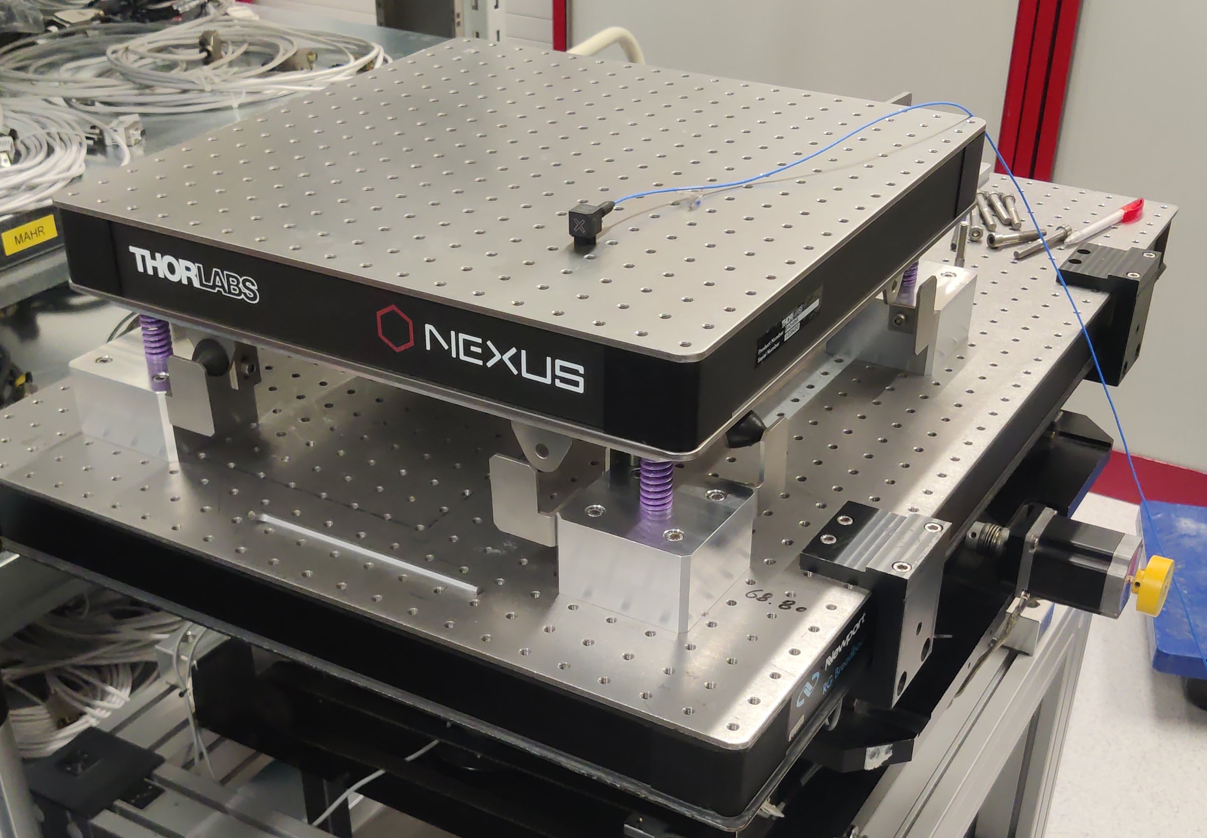
In order to identify the dynamics of the nano-hexapod, a special suspended table is developed which consists of a stiff "optical breadboard" suspended on top of four soft springs. The Nano-Hexapod is then fixed on top of the suspended table, such that its dynamics is not affected by complex dynamics except from the suspension modes of the table that can be well characterized and modelled (Section ref:sec:test_nhexa_table).
The obtained nano-hexapod dynamics is analyzed in Section ref:sec:test_nhexa_dynamics, and compared with the Simscape model in Section ref:sec:test_nhexa_model.
Nano-Hexapod Assembly Procedure
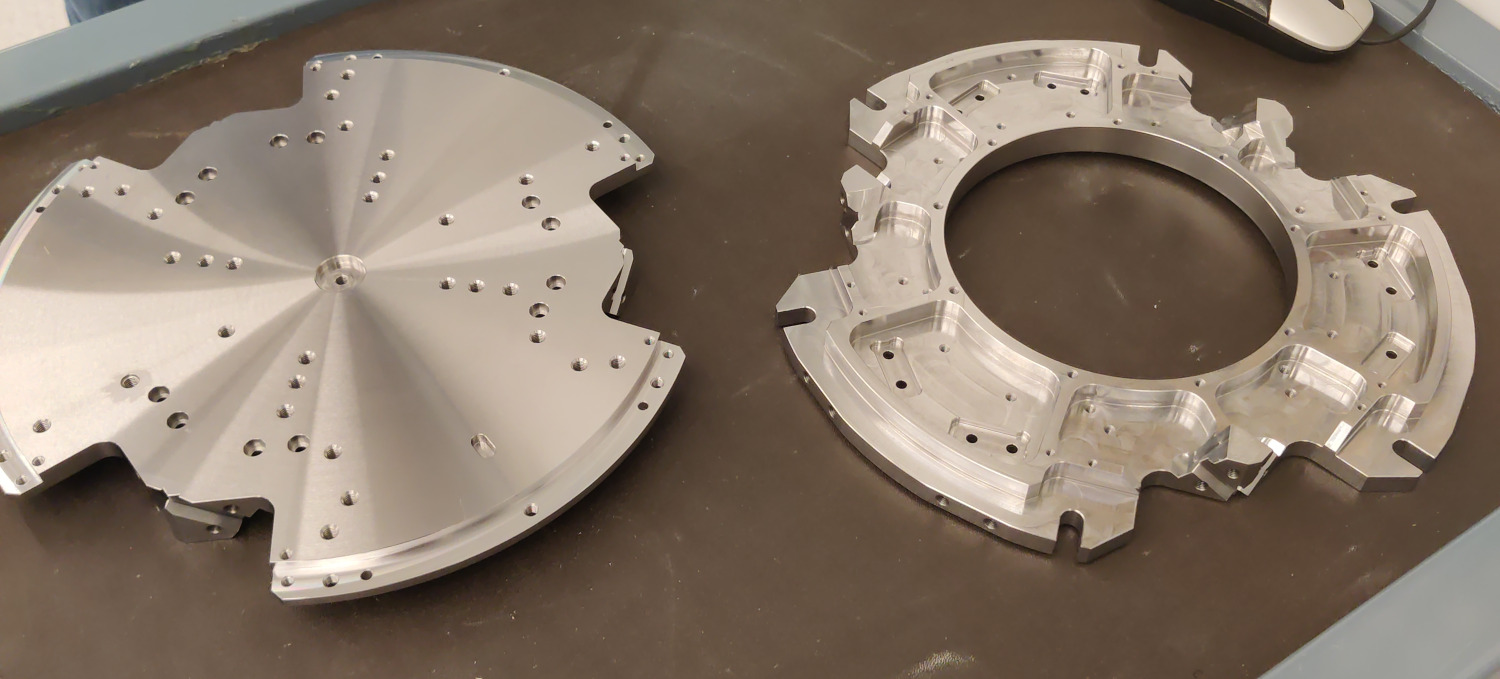
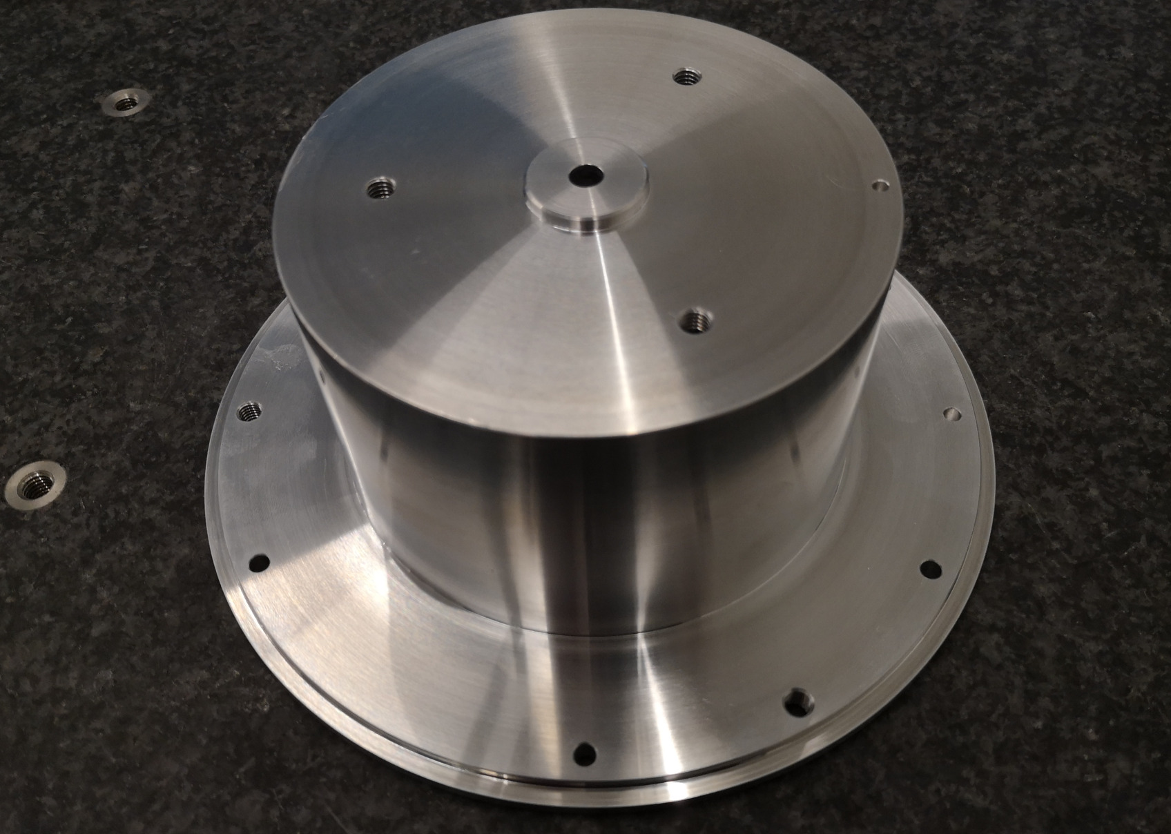
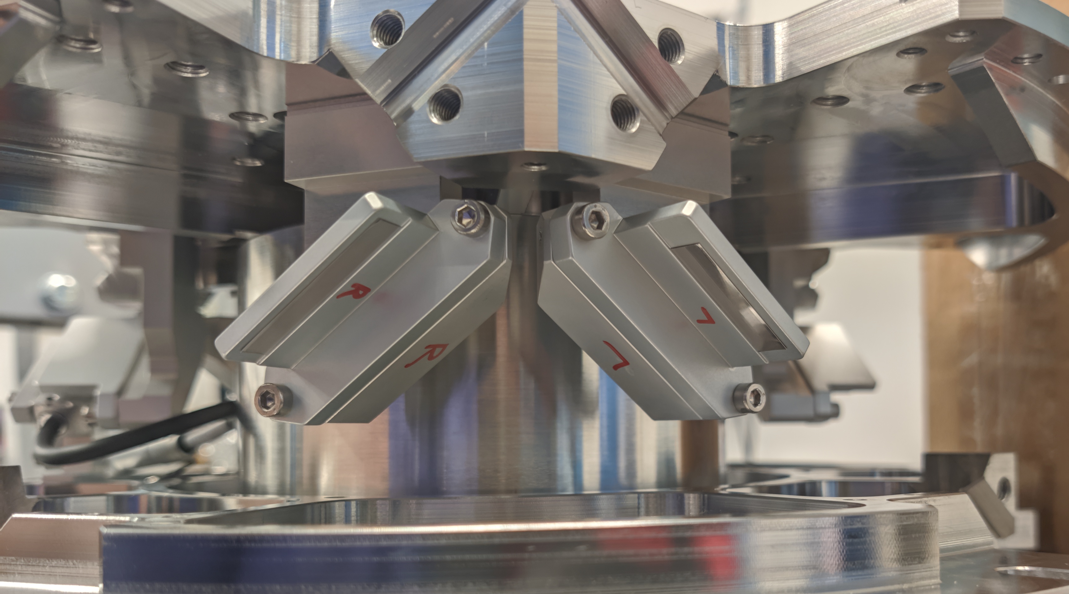
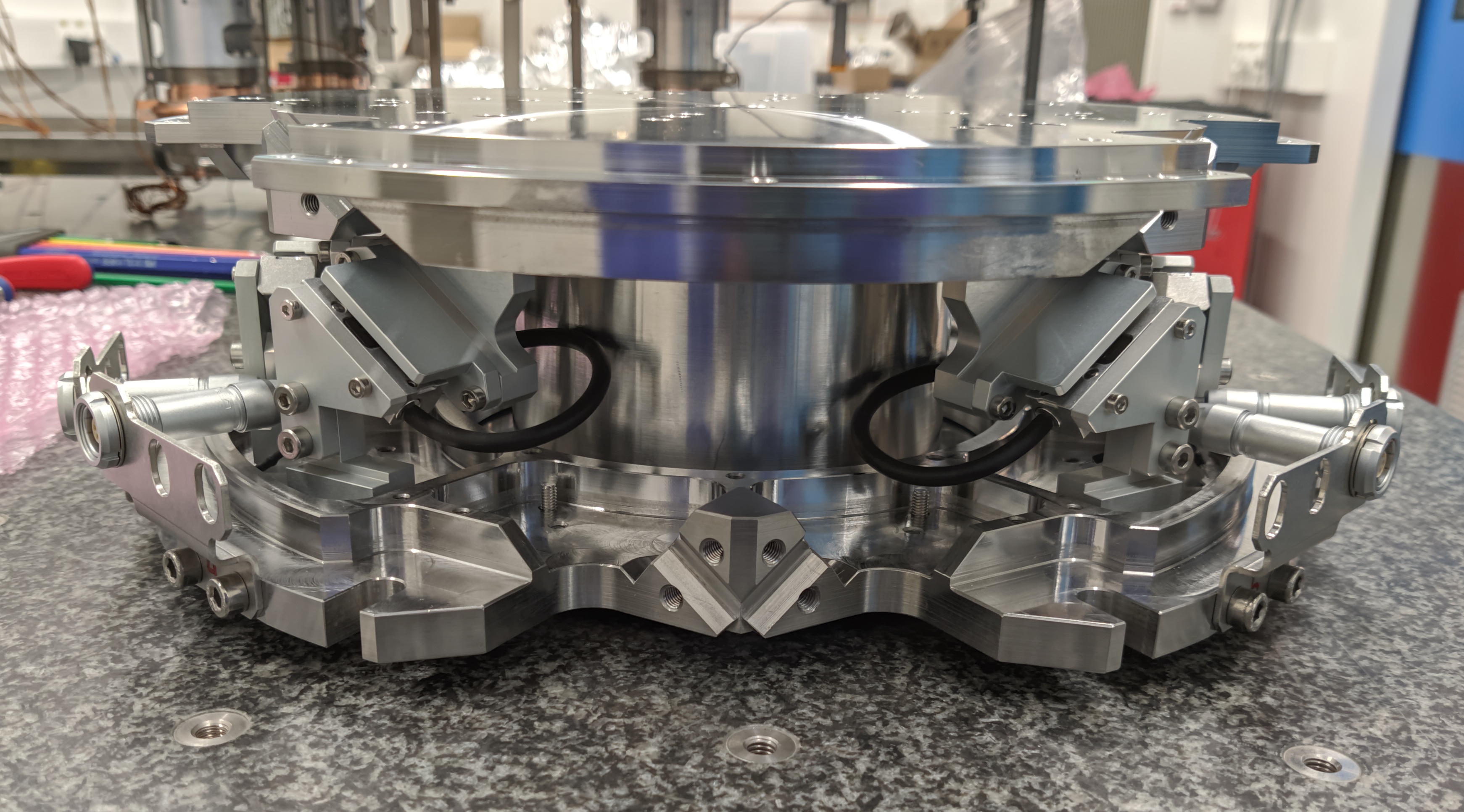
<<sec:test_nhexa_mounting>> The assembly of the nano-hexapod is quite critical to both avoid additional stress in the flexible joints (that would result in a loss of stroke) and for the precise determination of the Jacobian matrix. The goal is to fix the six struts to the two nano-hexapod plates (shown in Figure ref:fig:test_nhexa_nano_hexapod_plates) while the two plates are parallel, aligned vertically, and such that all the flexible joints do not experience any stress. Do to so, a precisely machined mounting tool (Figure ref:fig:test_nhexa_center_part_hexapod_mounting) is used to position the two nano-hexapod plates during the assembly procedure.
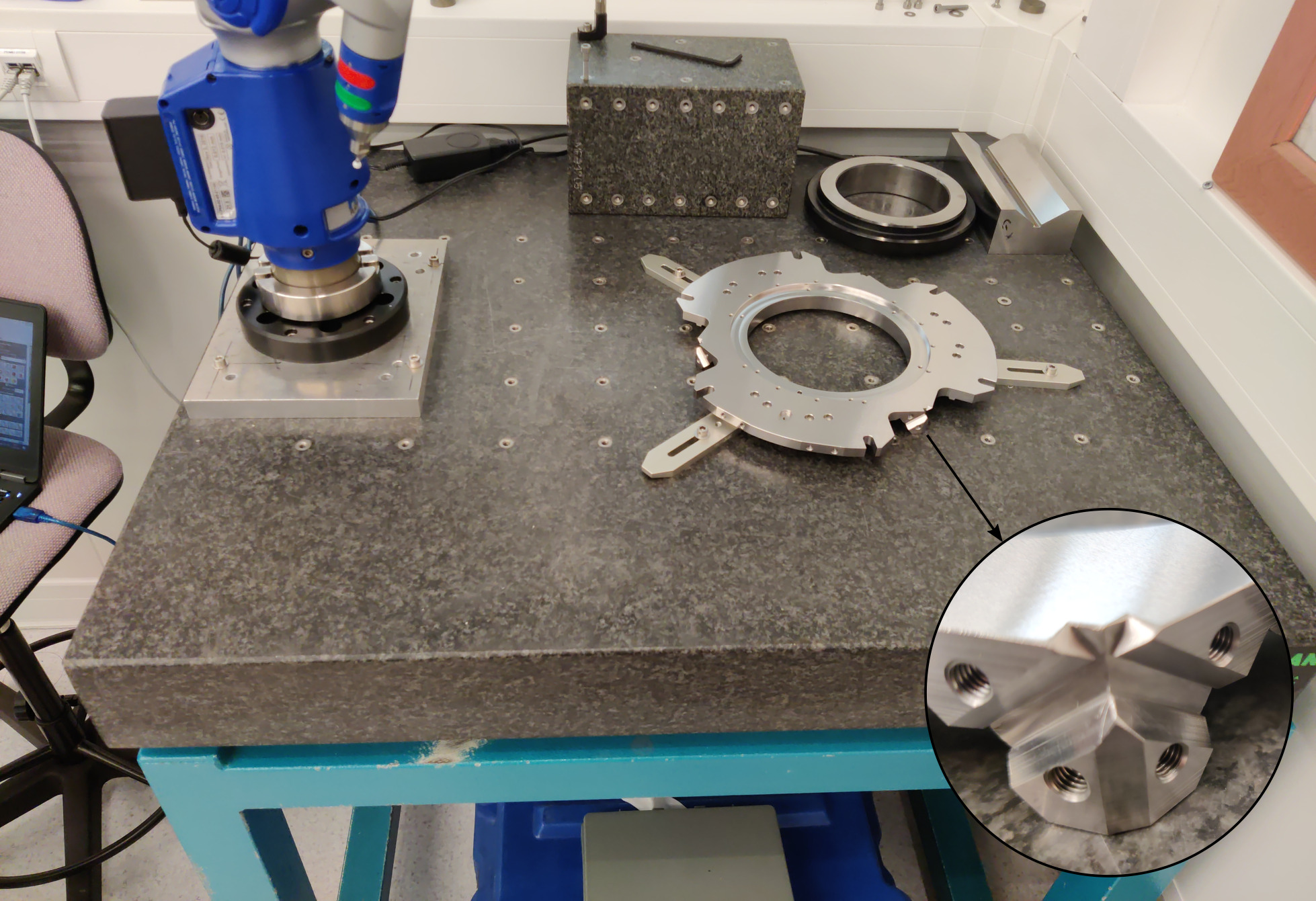
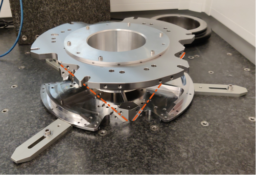
The mechanical tolerances of the received plates are checked using a FARO arm1 (Figure ref:fig:test_nhexa_plates_tolerances) and are found to comply with the requirements2. The same is done for the mounting tool3 The two plates are then fixed to the mounting tool as shown in Figure ref:fig:test_nhexa_mounting_tool_hexapod_top_view. The main goal of this "mounting tool" is to position the flexible joint interfaces (the "V" shapes) of both plates such that a cylinder can rest on the 4 flat interfaces at the same time.
The quality of the positioning can be estimated by measuring the "straightness" of the top and bottom "V" interfaces. This corresponds to the diameter of the smallest cylinder that contains all points of the measured axis. This is again done using the FARO arm, and the results for all the six struts are summarized in Table ref:tab:measured_straightness. The straightness is found to be better than $15\,\mu m$ for all the struts4, which is sufficiently good to not induce significant stress of the flexible joint during the assembly.
| Strut | Meas 1 | Meas 2 |
|---|---|---|
| 1 | $7\,\mu m$ | $3\, \mu m$ |
| 2 | $11\, \mu m$ | $11\, \mu m$ |
| 3 | $15\, \mu m$ | $14\, \mu m$ |
| 4 | $6\, \mu m$ | $6\, \mu m$ |
| 5 | $7\, \mu m$ | $5\, \mu m$ |
| 6 | $6\, \mu m$ | $7\, \mu m$ |
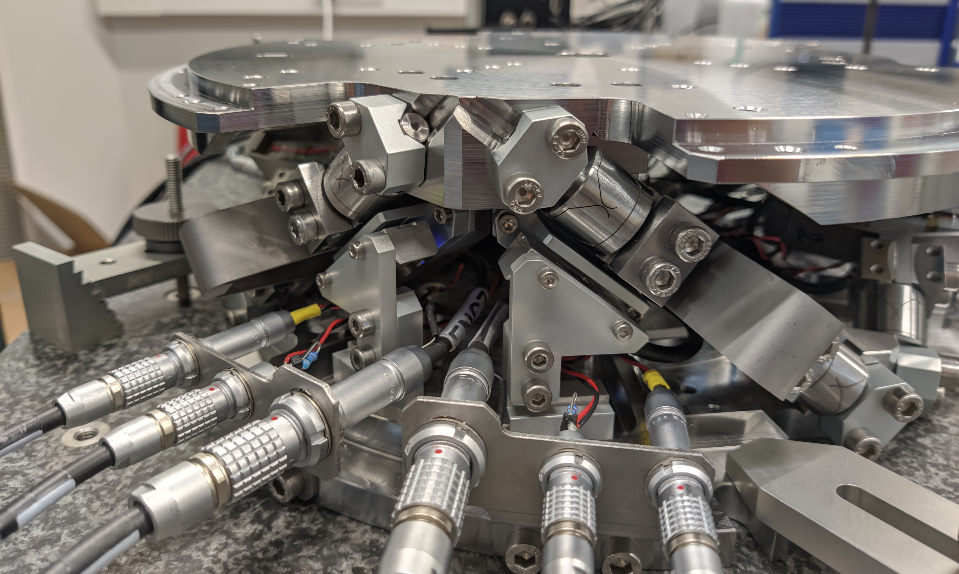
The encoder rulers and heads are then fixed to the top and bottom plates respectively (Figure ref:fig:test_nhexa_mount_encoder). The encoder heads are then aligned to maximize the received contrast.
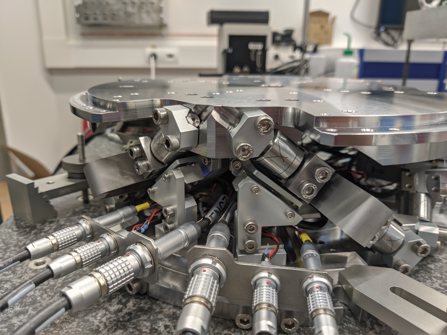
The six struts are then fixed to the bottom and top plates one by one. First the top flexible joint is fixed such that its flat reference surface is in contact with the top plate. This is to precisely known the position of the flexible joint with respect to the top plate. Then the bottom flexible joint is fixed. After all six struts are mounted, the mounting tool (Figure ref:fig:test_nhexa_center_part_hexapod_mounting) can be disassembled, and the fully mounted nano-hexapod as shown in Figure ref:fig:test_nhexa_nano_hexapod_mounted is obtained.
Suspended Table
<<sec:test_nhexa_table>>
Introduction
When a dynamical system is fixed to a support (such as a granite or an optical table), its dynamics will couple to the support dynamics. This may results in additional modes appearing in the system dynamics, which are difficult to predict and model. Two prevent this issue, strategy adopted here is to mount the nano-hexapod on top a suspended table with low frequency suspension modes.
In such a case, the modes of the suspended table are chosen to be at much lower frequency than those of the nano-hexapod such that they are well decoupled. An other key advantage is that the suspension modes of the suspended table can be easily modelled using Simscape. Therefore, the measured dynamics of the nano-hexapod on top of the suspended table can be compared to a simscape model representing the same experimental conditions. The model of the Nano-Hexapod can thus be precisely tuned to match the measured dynamics.
The developed suspended table is presented in Section ref:ssec:test_nhexa_table_setup. The modal analysis of the table is done in ref:ssec:test_nhexa_table_identification. Finally, the Simscape model representing the suspended table is tuned to match the measured modes (Section ref:ssec:test_nhexa_table_model).
Experimental Setup
<<ssec:test_nhexa_table_setup>>
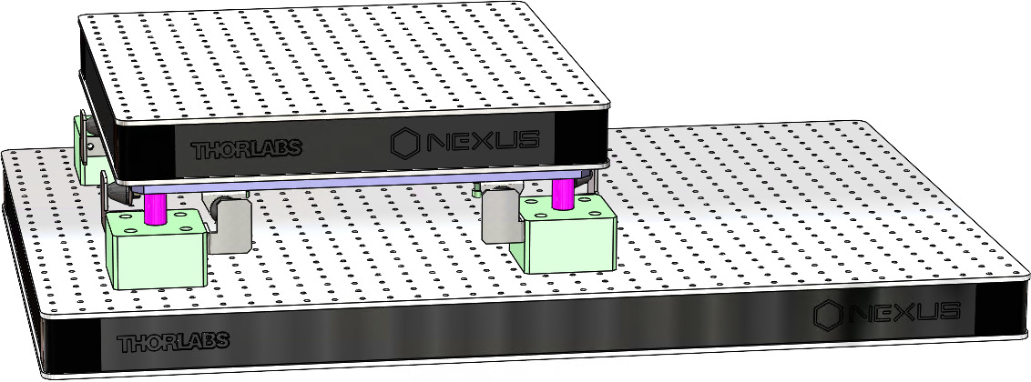
The design of the suspended table is quite straightforward. First, an optical table with high frequency flexible mode was selected5. Then, four springs6 were selected with low enough spring rate such that the suspension modes are below 10Hz. Finally, some interface elements were designed, and mechanical lateral mechanical stops were added (Figure ref:fig:test_nhexa_suspended_table_cad).
Modal analysis of the suspended table
<<ssec:test_nhexa_table_identification>>
In order to perform a modal analysis of the suspended table, a total of 15 3-axis accelerometers7 were fixed to the breadboard. Using an instrumented hammer, the first 9 modes could be identified and are summarized in Table ref:tab:test_nhexa_suspended_table_modes. The first 6 modes are suspension modes (i.e. rigid body mode of the breadboard) and are located below 10Hz. The next modes are flexible modes of the breadboard as shown in Figure ref:fig:test_nhexa_table_flexible_modes, and located above 700Hz.
\hfill
| Modes | Frequency | Description |
|---|---|---|
| 1,2 | 1.3 Hz | X-Y translations |
| 3 | 2.0 Hz | Z rotation |
| 4 | 6.9 Hz | Z translation |
| 5,6 | 9.5 Hz | X-Y rotations |
| 7 | 701 Hz | "Membrane" Mode |
| 8 | 989 Hz | Complex mode |
| 9 | 1025 Hz | Complex mode |
Simscape Model of the suspended table
<<ssec:test_nhexa_table_model>>
The Simscape model of the suspended table simply consists of two solid bodies connected by 4 springs. The 4 springs are here modelled with "bushing joints" that have stiffness and damping properties in x, y and z directions. The 3D representation of the model is displayed in Figure ref:fig:test_nhexa_suspended_table_simscape where the 4 "bushing joints" are represented by the blue cylinders.
The model order is 12, and it represents the 6 suspension modes. The inertia properties of the parts are set from the geometry and material densities. The stiffness of the springs was initially set from the datasheet nominal value of $17.8\,N/mm$ and then reduced down to $14\,N/mm$ to better match the measured suspension modes. The stiffness of the springs in the horizontal plane is set at $0.5\,N/mm$. The obtained suspension modes of the simscape model are compared with the measured ones in Table ref:tab:test_nhexa_suspended_table_simscape_modes.
%% Configure Simscape Model
table_type = 'Suspended'; % On top of vibration table
device_type = 'None'; % No device on the vibration table
payload_num = 0; % No Payload

%% Input/Output definition
clear io; io_i = 1;
io(io_i) = linio([mdl, '/F'],      1, 'openinput');  io_i = io_i + 1;
io(io_i) = linio([mdl, '/F_v'],  1, 'openoutput'); io_i = io_i + 1;

%% Run the linearization
G = linearize(mdl, io);
G.InputName  = {'Fx', 'Fy', 'Fz', 'Mx', 'My', 'Mz'};
G.OutputName  = {'Vdx', 'Vdy', 'Vdz', 'Vrx', 'Vry', 'Vrz'};

%% Compute the resonance frequencies
ws = eig(G.A);
ws = ws(imag(ws) > 0);| Directions | $D_x$, $D_y$ | $R_z$ | $D_z$ | $R_x$, $R_y$ |
|---|---|---|---|---|
| Experimental | 1.3 Hz | 2.0 Hz | 6.9 Hz | 9.5 Hz |
| Simscape | 1.3 Hz | 1.8 Hz | 6.8 Hz | 9.5 Hz |
Nano-Hexapod Dynamics
<<sec:test_nhexa_dynamics>>
Introduction ignore
In Figure ref:fig:test_nhexa_nano_hexapod_signals is shown a block diagram of the experimental setup. When possible, the notations are consistent with this diagram and summarized in Table ref:tab:list_signals.
\definecolor{instrumentation}{rgb}{0, 0.447, 0.741}
\definecolor{mechanics}{rgb}{0.8500, 0.325, 0.098}

\begin{tikzpicture}
  % Blocs
  \node[block={4.0cm}{3.0cm}, fill=mechanics!20!white] (nano_hexapod) {Mechanics};
  \coordinate[] (inputF)  at (nano_hexapod.west);
  \coordinate[] (outputL) at ($(nano_hexapod.south east)!0.8!(nano_hexapod.north east)$);
  \coordinate[] (outputF) at ($(nano_hexapod.south east)!0.2!(nano_hexapod.north east)$);

  \node[block, left= 0.8 of inputF,  fill=instrumentation!20!white, align=center] (F_stack) {\tiny Actuator \\ \tiny stacks};
  \node[block, left= 0.8 of F_stack, fill=instrumentation!20!white] (PD200)   {PD200};
  \node[DAC,   left= 0.8 of PD200,   fill=instrumentation!20!white] (F_DAC)   {DAC};
  \node[block, right=0.8 of outputF, fill=instrumentation!20!white, align=center] (Fm_stack){\tiny Sensor \\ \tiny stack};
  \node[ADC,   right=0.8 of Fm_stack,fill=instrumentation!20!white] (Fm_ADC)  {ADC};
  \node[block, right=0.8 of outputL, fill=instrumentation!20!white] (encoder) {\tiny Encoder};

  % Connections and labels
  \draw[->] ($(F_DAC.west)+(-0.8,0)$) node[above right]{$\bm{u}$} node[below right]{$[V]$} -- node[sloped]{$/$} (F_DAC.west);
  \draw[->] (F_DAC.east)   -- node[midway, above]{$\tilde{\bm{u}}$}node[midway, below]{$[V]$} (PD200.west);
  \draw[->] (PD200.east)   -- node[midway, above]{$\bm{u}_a$}node[midway, below]{$[V]$} (F_stack.west);
  \draw[->] (F_stack.east) -- (inputF) node[above left]{$\bm{\tau}$}node[below left]{$[N]$};

  \draw[->] (outputF)       -- (Fm_stack.west) node[above left]{$\bm{\epsilon}$} node[below left]{$[m]$};
  \draw[->] (Fm_stack.east) -- node[midway, above]{$\tilde{\bm{\tau}}_m$}node[midway, below]{$[V]$} (Fm_ADC.west);
  \draw[->] (Fm_ADC.east)   -- node[sloped]{$/$} ++(0.8, 0)coordinate(end) node[above left]{$\bm{\tau}_m$}node[below left]{$[V]$};

  \draw[->] (outputL)      -- (encoder.west) node[above left]{$d\bm{\mathcal{L}}$} node[below left]{$[m]$};
  \draw[->] (encoder.east) -- node[sloped]{$/$} (encoder-|end) node[above left]{$d\bm{\mathcal{L}}_m$}node[below left]{$[m]$};

  % Nano-Hexapod
  \begin{scope}[on background layer]
    \node[fit={(F_stack.west|-nano_hexapod.south) (Fm_stack.east|-nano_hexapod.north)}, fill=black!20!white, draw, inner sep=2pt] (system) {};
    \node[above] at (system.north) {Nano-Hexapod};
  \end{scope}
\end{tikzpicture}| Unit | Matlab | Vector | Elements | |
|---|---|---|---|---|
| Control Input (wanted DAC voltage) | [V] |
u |
$\bm{u}$ | $u_i$ |
| DAC Output Voltage | [V] |
u |
$\tilde{\bm{u}}$ | $\tilde{u}_i$ |
| PD200 Output Voltage | [V] |
ua |
$\bm{u}_a$ | $u_{a,i}$ |
| Actuator applied force | [N] |
tau |
$\bm{\tau}$ | $\tau_i$ |
| Strut motion | [m] |
dL |
$d\bm{\mathcal{L}}$ | $d\mathcal{L}_i$ |
| Encoder measured displacement | [m] |
dLm |
$d\bm{\mathcal{L}}_m$ | $d\mathcal{L}_{m,i}$ |
| Force Sensor strain | [m] |
epsilon |
$\bm{\epsilon}$ | $\epsilon_i$ |
| Force Sensor Generated Voltage | [V] |
taum |
$\tilde{\bm{\tau}}_m$ | $\tilde{\tau}_{m,i}$ |
| Measured Generated Voltage | [V] |
taum |
$\bm{\tau}_m$ | $\tau_{m,i}$ |
| Motion of the top platform | [m,rad] |
dX |
$d\bm{\mathcal{X}}$ | $d\mathcal{X}_i$ |
| Metrology measured displacement | [m,rad] |
dXm |
$d\bm{\mathcal{X}}_m$ | $d\mathcal{X}_{m,i}$ |
It is structured as follow:
- Section ref:sec:test_nhexa_enc_plates_plant_id: The dynamics of the nano-hexapod is identified.
- Section ref:sec:test_nhexa_enc_plates_comp_simscape: The identified dynamics is compared with the Simscape model.
Identification of the dynamics
<<sec:test_nhexa_enc_plates_plant_id>>
Introduction ignore
In this section, the dynamics of the nano-hexapod with the encoders fixed to the plates is identified.
First, the measurement data are loaded in Section ref:sec:test_nhexa_enc_plates_plant_id_setup, then the transfer function matrix from the actuators to the encoders are estimated in Section ref:sec:test_nhexa_enc_plates_plant_id_dvf. Finally, the transfer function matrix from the actuators to the force sensors is estimated in Section ref:sec:test_nhexa_enc_plates_plant_id_iff.
Data Loading and Spectral Analysis Setup
<<sec:test_nhexa_enc_plates_plant_id_setup>>
The actuators are excited one by one using a low pass filtered white noise. For each excitation, the 6 force sensors and 6 encoders are measured and saved.
%% Load Identification Data
meas_data = {};

for i = 1:6
    meas_data(i) = {load(sprintf('frf_data_exc_strut_%i_realigned_vib_table_0m.mat', i), 't', 'Va', 'Vs', 'de')};
end
Transfer function from Actuator to Encoder
<<sec:test_nhexa_enc_plates_plant_id_dvf>>
The 6x6 transfer function matrix from the excitation voltage $\bm{u}$ and the displacement $d\bm{\mathcal{L}}_m$ as measured by the encoders is estimated.
%% Transfer function from u to dLm
G_dL = zeros(length(f), 6, 6);

for i = 1:6
    G_dL(:,:,i) = tfestimate(meas_data{i}.Va, meas_data{i}.de, win, Noverlap, Nfft, 1/Ts);
end
The diagonal and off-diagonal terms of this transfer function matrix are shown in Figure ref:fig:test_nhexa_enc_plates_dvf_frf.
From Figure ref:fig:test_nhexa_enc_plates_dvf_frf, we can draw few conclusions on the transfer functions from $\bm{u}$ to $d\bm{\mathcal{L}}_m$ when the encoders are fixed to the plates:
- the decoupling is rather good at low frequency (below the first suspension mode). The low frequency gain is constant for the off diagonal terms, whereas when the encoders where fixed to the struts, the low frequency gain of the off-diagonal terms were going to zero (Figure ref:fig:test_nhexa_enc_struts_dvf_frf).
- the flexible modes of the struts at 226Hz and 337Hz are indeed shown in the transfer functions, but their amplitudes are rather low.
- the diagonal terms have alternating poles and zeros up to at least 600Hz: the flexible modes of the struts are not affecting the alternating pole/zero pattern. This what not the case when the encoders were fixed to the struts (Figure ref:fig:test_nhexa_enc_struts_dvf_frf).
Transfer function from Actuator to Force Sensor
<<sec:test_nhexa_enc_plates_plant_id_iff>> Then the 6x6 transfer function matrix from the excitation voltage $\bm{u}$ and the voltage $\bm{\tau}_m$ generated by the Force senors is estimated.
%% IFF Plant
G_tau = zeros(length(f), 6, 6);

for i = 1:6
    G_tau(:,:,i) = tfestimate(meas_data{i}.Va, meas_data{i}.Vs, win, Noverlap, Nfft, 1/Ts);
end
The bode plot of the diagonal and off-diagonal terms are shown in Figure ref:fig:test_nhexa_enc_plates_iff_frf.
It is shown in Figure ref:fig:test_nhexa_enc_plates_iff_comp_simscape_all that:
- The IFF plant has alternating poles and zeros
- The first flexible mode of the struts as 235Hz is appearing, and therefore is should be possible to add some damping to this mode using IFF
- The decoupling is quite good at low frequency (below the first model) as well as high frequency (above the last suspension mode, except near the flexible modes of the top plate)
Save Identified Plants
The identified dynamics is saved for further use.
save('data_frf/mat/identified_plants_enc_plates.mat', 'f', 'Ts', 'G_tau', 'G_dL')Effect of Payload mass on the Dynamics
<<sec:test_nhexa_added_mass>>
Introduction ignore
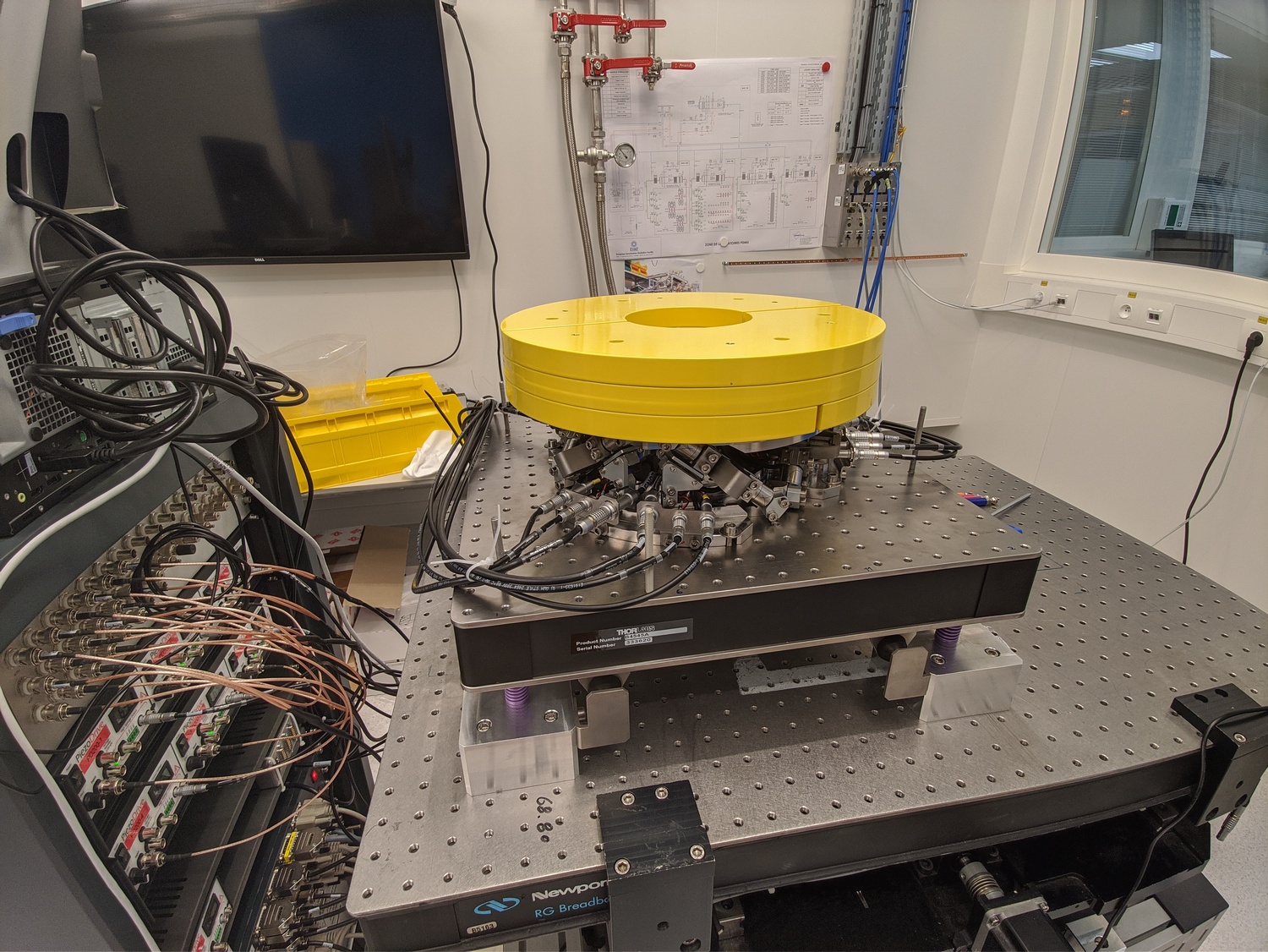
In this section, the encoders are fixed to the plates, and we identify the dynamics for several payloads. The added payload are half cylinders, and three layers can be added for a total of around 40kg (Figure ref:fig:test_nhexa_picture_added_3_masses).
First the dynamics from $\bm{u}$ to $d\mathcal{L}_m$ and $\bm{\tau}_m$ is identified. Then, the Integral Force Feedback controller is developed and applied as shown in Figure ref:fig:test_nhexa_nano_hexapod_signals_iff. Finally, the dynamics from $\bm{u}^\prime$ to $d\mathcal{L}_m$ is identified and the added damping can be estimated.
\definecolor{instrumentation}{rgb}{0, 0.447, 0.741}
\definecolor{mechanics}{rgb}{0.8500, 0.325, 0.098}
\definecolor{control}{rgb}{0.4660, 0.6740, 0.1880}

\begin{tikzpicture}
  % Blocs
  \node[block={4.0cm}{3.0cm}, fill=mechanics!20!white] (nano_hexapod) {Mechanics};
  \coordinate[] (inputF)  at (nano_hexapod.west);
  \coordinate[] (outputL) at ($(nano_hexapod.south east)!0.8!(nano_hexapod.north east)$);
  \coordinate[] (outputF) at ($(nano_hexapod.south east)!0.2!(nano_hexapod.north east)$);

  \node[block, left= 0.8 of inputF,  fill=instrumentation!20!white, align=center] (F_stack) {\tiny Actuator \\ \tiny stacks};
  \node[block, left= 0.8 of F_stack, fill=instrumentation!20!white] (PD200)   {PD200};
  \node[DAC,   left= 0.8 of PD200,   fill=instrumentation!20!white] (F_DAC)   {DAC};
  \node[block, right=0.8 of outputF, fill=instrumentation!20!white, align=center] (Fm_stack){\tiny Sensor \\ \tiny stack};
  \node[ADC,   right=0.8 of Fm_stack,fill=instrumentation!20!white] (Fm_ADC)  {ADC};
  \node[block, right=0.8 of outputL, fill=instrumentation!20!white] (encoder) {\tiny Encoder};
  \node[addb,  left= 0.8 of F_DAC,   fill=control!20!white]         (add_iff) {};
  \node[block, below=0.8 of add_iff, fill=control!20!white]         (Kiff) {\tiny $K_{\text{IFF}}(s)$};

  % Connections and labels
  \draw[->] (add_iff.east) node[above right]{$\bm{u}$} node[below right]{$[V]$} -- node[sloped]{$/$} (F_DAC.west);
  \draw[->] (F_DAC.east)   -- node[midway, above]{$\tilde{\bm{u}}$}node[midway, below]{$[V]$} (PD200.west);
  \draw[->] (PD200.east)   -- node[midway, above]{$\bm{u}_a$}node[midway, below]{$[V]$} (F_stack.west);
  \draw[->] (F_stack.east) -- (inputF) node[above left]{$\bm{\tau}$}node[below left]{$[N]$};

  \draw[->] (outputF)       -- (Fm_stack.west) node[above left]{$\bm{\epsilon}$} node[below left]{$[m]$};
  \draw[->] (Fm_stack.east) -- node[midway, above]{$\tilde{\bm{\tau}}_m$}node[midway, below]{$[V]$} (Fm_ADC.west);
  \draw[->] (Fm_ADC.east)   -- node[sloped]{$/$} ++(0.8, 0)coordinate(end) node[above left]{$\bm{\tau}_m$}node[below left]{$[V]$};

  \draw[->] (outputL)      -- (encoder.west) node[above left]{$d\bm{\mathcal{L}}$} node[below left]{$[m]$};
  \draw[->] (encoder.east) -- node[sloped]{$/$} (encoder-|end) node[above left]{$d\bm{\mathcal{L}}_m$}node[below left]{$[m]$};

  \draw[->] ($(Fm_ADC.east)+(0.14,0)$) node[branch]{} -- node[sloped]{$/$} ++(0, -1.8) -| (Kiff.south);
  \draw[->] (Kiff.north) -- node[sloped]{$/$} (add_iff.south);
  \draw[->] ($(add_iff.west)+(-0.8,0)$) node[above right]{$\bm{u}^\prime$} node[below right]{$[V]$} -- node[sloped]{$/$} (add_iff.west);

  % Nano-Hexapod
  \begin{scope}[on background layer]
    \node[fit={(F_stack.west|-nano_hexapod.south) (Fm_stack.east|-nano_hexapod.north)}, fill=black!20!white, draw, inner sep=2pt] (system) {};
    \node[above] at (system.north) {Nano-Hexapod};
  \end{scope}
\end{tikzpicture}Measured Frequency Response Functions
The following data are loaded:
Va: the excitation voltage (corresponding to $u_i$)Vs: the generated voltage by the 6 force sensors (corresponding to $\bm{\tau}_m$)de: the measured motion by the 6 encoders (corresponding to $d\bm{\mathcal{L}}_m$)
%% Load Identification Data
meas_added_mass = {};

for i_mass = i_masses
    for i_strut = 1:6
        meas_added_mass(i_strut, i_mass+1) = {load(sprintf('frf_data_exc_strut_%i_realigned_vib_table_%im.mat', i_strut, i_mass), 't', 'Va', 'Vs', 'de')};
    end
end
The window win and the frequency vector f are defined.
Finally the $6 \times 6$ transfer function matrices from $\bm{u}$ to $d\bm{\mathcal{L}}_m$ and from $\bm{u}$ to $\bm{\tau}_m$ are identified:
%% DVF Plant (transfer function from u to dLm)
G_dL = {};

for i_mass = i_masses
    G_dL(i_mass+1) = {zeros(length(f), 6, 6)};
    for i_strut = 1:6
        G_dL{i_mass+1}(:,:,i_strut) = tfestimate(meas_added_mass{i_strut, i_mass+1}.Va, meas_added_mass{i_strut, i_mass+1}.de, win, Noverlap, Nfft, 1/Ts);
    end
end

%% IFF Plant (transfer function from u to taum)
G_tau = {};

for i_mass = i_masses
    G_tau(i_mass+1) = {zeros(length(f), 6, 6)};
    for i_strut = 1:6
        G_tau{i_mass+1}(:,:,i_strut) = tfestimate(meas_added_mass{i_strut, i_mass+1}.Va, meas_added_mass{i_strut, i_mass+1}.Vs, win, Noverlap, Nfft, 1/Ts);
    end
end
The identified dynamics are then saved for further use.
save('data_frf/mat/frf_vib_table_m.mat', 'f', 'Ts', 'G_tau', 'G_dL')Transfer function from Actuators to Encoders
The transfer functions from $\bm{u}$ to $d\bm{\mathcal{L}}_{m}$ are shown in Figure ref:fig:test_nhexa_comp_plant_payloads_dvf.
From Figure ref:fig:test_nhexa_comp_plant_payloads_dvf, we can observe few things:
- The obtained dynamics is changing a lot between the case without mass and when there is at least one added mass.
- Between 1, 2 and 3 added masses, the dynamics is not much different, and it would be easier to design a controller only for these cases.
- The flexible modes of the top plate is first decreased a lot when the first mass is added (from 700Hz to 400Hz). This is due to the fact that the added mass is composed of two half cylinders which are not fixed together. Therefore is adds a lot of mass to the top plate without adding a lot of rigidity in one direction. When more than 1 mass layer is added, the half cylinders are added with some angles such that rigidity are added in all directions (see Figure ref:fig:test_nhexa_picture_added_3_masses). In that case, the frequency of these flexible modes are increased. In practice, the payload should be one solid body, and we should not see a massive decrease of the frequency of this flexible mode.
- Flexible modes of the top plate are becoming less problematic as masses are added.
- First flexible mode of the strut at 230Hz is not much decreased when mass is added. However, its apparent amplitude is much decreased.
Transfer function from Actuators to Force Sensors
The transfer functions from $\bm{u}$ to $\bm{\tau}_{m}$ are shown in Figure ref:fig:test_nhexa_comp_plant_payloads_iff.
From Figure ref:fig:test_nhexa_comp_plant_payloads_iff, we can see that for all added payloads, the transfer function from $\bm{u}$ to $\bm{\tau}_{m}$ always has alternating poles and zeros.
Coupling of the transfer function from Actuator to Encoders
The RGA-number, which is a measure of the interaction in the system, is computed for the transfer function matrix from $\bm{u}$ to $d\bm{\mathcal{L}}_m$ for all the payloads. The obtained numbers are compared in Figure ref:fig:test_nhexa_rga_num_ol_masses.
From Figure ref:fig:test_nhexa_rga_num_ol_masses, it is clear that the coupling is quite large starting from the first suspension mode of the nano-hexapod. Therefore, is the payload's mass is increase, the coupling in the system start to become unacceptably large at lower frequencies.
Conclusion
In this section, the dynamics of the nano-hexapod with the encoders fixed to the plates is studied.
It has been found that:
- The measured dynamics is in agreement with the dynamics of the simscape model, up to the flexible modes of the top plate. See figures ref:fig:test_nhexa_enc_plates_iff_comp_simscape and ref:fig:test_nhexa_enc_plates_iff_comp_offdiag_simscape for the transfer function to the force sensors and Figures ref:fig:test_nhexa_enc_plates_dvf_comp_simscape and ref:fig:test_nhexa_enc_plates_dvf_comp_offdiag_simscape for the transfer functions to the encoders
- The Integral Force Feedback strategy is very effective in damping the suspension modes of the nano-hexapod (Figure ref:fig:test_nhexa_enc_plant_plates_effect_iff).
- The transfer function from $\bm{u}^\prime$ to $d\bm{\mathcal{L}}_m$ show nice dynamical properties and is a much better candidate for the high-authority-control than when the encoders were fixed to the struts. At least up to the flexible modes of the top plate, the diagonal elements of the transfer function matrix have alternating poles and zeros, and the phase is moving smoothly. Only the flexible modes of the top plates seems to be problematic for control.
Comparison with the Nano-Hexapod model?
<<sec:test_nhexa_model>>
Comparison with the Simscape Model
<<sec:test_nhexa_enc_plates_comp_simscape>>
Introduction ignore
In this section, the measured dynamics done in Section ref:sec:test_nhexa_enc_plates_plant_id is compared with the dynamics estimated from the Simscape model.
A configuration is added to be able to put the nano-hexapod on top of the vibration table as shown in Figure ref:fig:simscape_vibration_table.
Identification with the Simscape Model
The nano-hexapod is initialized with the APA taken as 2dof models.
%% Initialize Simscape Model
table_type = 'Suspended'; % On top of vibration table
device_type = 'Hexapod'; % On top of vibration table
payload_num = 0; % No Payload

n_hexapod = initializeNanoHexapodFinal('flex_bot_type', '4dof', ...
                                       'flex_top_type', '4dof', ...
                                       'motion_sensor_type', 'plates', ...
                                       'actuator_type', '2dof');
Now, the dynamics from the DAC voltage $\bm{u}$ to the encoders $d\bm{\mathcal{L}}_m$ is estimated using the Simscape model.
%% Identify the DVtransfer function from u to dLm
clear io; io_i = 1;
io(io_i) = linio([mdl, '/u'],  1, 'openinput');  io_i = io_i + 1; % Actuator Inputs
io(io_i) = linio([mdl, '/dL'], 1, 'openoutput'); io_i = io_i + 1; % Encoders

G_dL = exp(-s*frf_ol.Ts)*linearize(mdl, io, 0.0, options);
Then the transfer function from $\bm{u}$ to $\bm{\tau}_m$ is identified using the Simscape model.
%% Identify the transfer function from u to taum
clear io; io_i = 1;
io(io_i) = linio([mdl, '/u'], 1, 'openinput');   io_i = io_i + 1; % Actuator Inputs
io(io_i) = linio([mdl, '/Fm'], 1, 'openoutput'); io_i = io_i + 1; % Force Sensors

G_tau = exp(-s*frf_ol.Ts)*linearize(mdl, io, 0.0, options);
The identified dynamics is saved for further use.
save('mat/data_frf/simscape_plants_enc_plates.mat', 'G_tau', 'G_dL');Dynamics from Actuator to Force Sensors
The identified dynamics is compared with the measured FRF:
- Figure ref:fig:test_nhexa_enc_plates_iff_comp_simscape_all: the individual transfer function from $u_1$ (the DAC voltage for the first actuator) to the force sensors of all 6 struts are compared
- Figure ref:fig:test_nhexa_enc_plates_iff_comp_simscape: all the diagonal elements are compared
- Figure ref:fig:test_nhexa_enc_plates_iff_comp_offdiag_simscape: all the off-diagonal elements are compared
Dynamics from Actuator to Encoder
The identified dynamics is compared with the measured FRF:
- Figure ref:fig:test_nhexa_enc_plates_dvf_comp_simscape_all: the individual transfer function from $u_3$ (the DAC voltage for the actuator number 3) to the six encoders
- Figure ref:fig:test_nhexa_enc_plates_dvf_comp_simscape: all the diagonal elements are compared
- Figure ref:fig:test_nhexa_enc_plates_dvf_comp_offdiag_simscape: all the off-diagonal elements are compared
Conclusion
The Simscape model is quite accurate for the transfer function matrices from $\bm{u}$ to $\bm{\tau}_m$ and from $\bm{u}$ to $d\bm{\mathcal{L}}_m$ except at frequencies of the flexible modes of the top-plate. The Simscape model can therefore be used to develop the control strategies.
Comparison with the Simscape model
<<sec:test_nhexa_added_mass_simscape>>
Introduction ignore
Let's now compare the identified dynamics with the Simscape model. We wish to verify if the Simscape model is still accurate for all the tested payloads.
System Identification
Let's initialize the simscape model with the nano-hexapod fixed on top of the vibration table.
%% Initialize Nano-Hexapod
table_type = 'Suspended'; % On top of vibration table
device_type = 'Hexapod'; % On top of vibration table
payload_num = 0; % No Payload

n_hexapod = initializeNanoHexapodFinal('flex_bot_type', '4dof', ...
                                       'flex_top_type', '4dof', ...
                                       'motion_sensor_type', 'plates', ...
                                       'actuator_type', '2dof');
First perform the identification for the transfer functions from $\bm{u}$ to $d\bm{\mathcal{L}}_m$:
%% Identify the DVF Plant (transfer function from u to dLm)
clear io; io_i = 1;
io(io_i) = linio([mdl, '/u'],  1, 'openinput');  io_i = io_i + 1; % Actuator Inputs
io(io_i) = linio([mdl, '/dL'], 1, 'openoutput'); io_i = io_i + 1; % Encoders

%% Identification for all the added payloads
G_dL = {};

for i = i_masses
    fprintf('i = %i\n', i)
    payload_num = i; % Change the payload on the nano-hexapod
    G_dL(i+1) = {exp(-s*frf_ol_m.Ts)*linearize(mdl, io, 0.0, options)};
end
%% Identify the IFF Plant (transfer function from u to taum)
clear io; io_i = 1;
io(io_i) = linio([mdl, '/u'], 1, 'openinput'); io_i = io_i + 1; % Actuator Inputs
io(io_i) = linio([mdl, '/Fm'], 1, 'openoutput'); io_i = io_i + 1; % Force Sensors
%% Identification for all the added payloads
G_tau = {};
for i = 0:3
fprintf('i = %i\n', i)
payload_num = i; % Change the payload on the nano-hexapod
G_tau(i+1) = {exp(-s*frf_ol_m.Ts)*linearize(mdl, io, 0.0, options)};
endThe identified dynamics are then saved for further use.
save('./mat/data_frf/sim_vib_table_m.mat', 'G_tau', 'G_dL')Transfer function from Actuators to Encoders
The measured FRF and the identified dynamics from $u_i$ to $d\mathcal{L}_{m,i}$ are compared in Figure ref:fig:test_nhexa_comp_masses_model_exp_dvf. A zoom near the "suspension" modes is shown in Figure ref:fig:test_nhexa_comp_masses_model_exp_dvf_zoom.
The Simscape model is very accurately representing the measured dynamics up. Only the flexible modes of the struts and of the top plate are not represented here as these elements are modelled as rigid bodies.
Transfer function from Actuators to Force Sensors
The measured FRF and the identified dynamics from $u_i$ to $\tau_{m,i}$ are compared in Figure ref:fig:test_nhexa_comp_masses_model_exp_iff. A zoom near the "suspension" modes is shown in Figure ref:fig:test_nhexa_comp_masses_model_exp_iff_zoom.
Bibliography ignore
Glossary ignore
Footnotes
7PCB 356B18. Sensitivity is $1\,V/g$, measurement range is $\pm 5\,g$ and bandwidth is $0.5$ to $5\,\text{kHz}$. 6"SZ8005 20 x 044" from Steinel. The spring rate is specified at $17.8\,N/mm$ 5The 450 mm x 450 mm x 60 mm Nexus B4545A from Thorlabs. 4As the accuracy of the FARO arm is $\pm 13\,\mu m$, the true straightness is probably better than the values indicated. The limitation of the instrument is here reached. 3The height dimension is better than $40\,\mu m$. The diameter fit of 182g6 and 24g6 with the two plates is verified. 2Location of all the interface surfaces with the flexible joints are checked. The fits (182H7 and 24H8) with the interface element are checked. 1Faro Arm Platinum 4ft, specified accuracy of $\pm 13\mu m$
