30 KiB
Nano Hexapod - Obtained Design
Introduction ignore
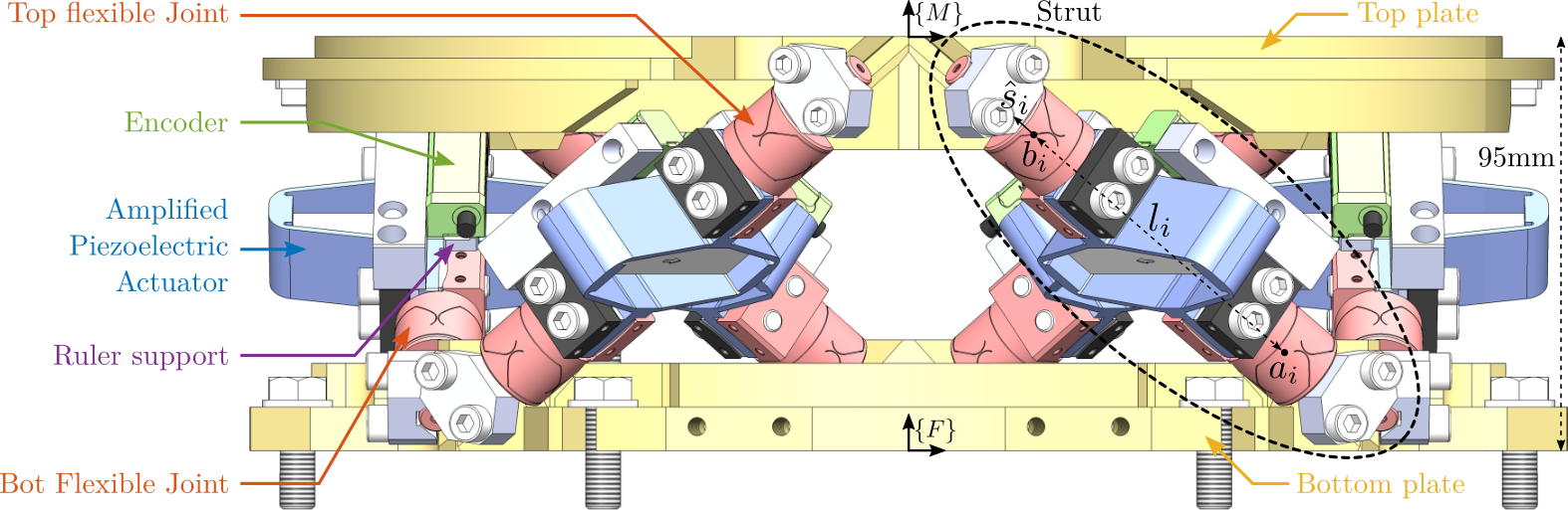
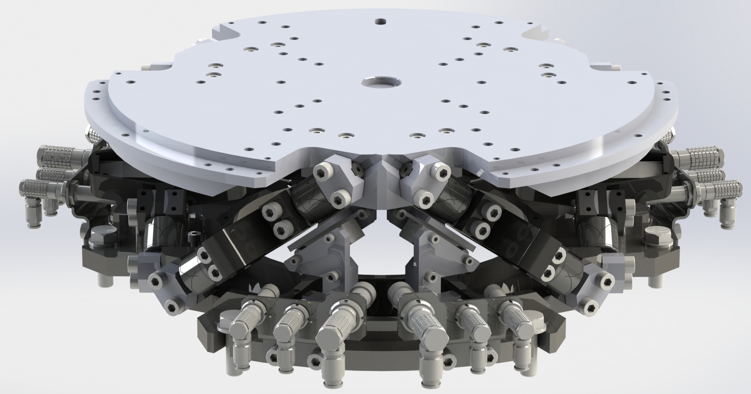
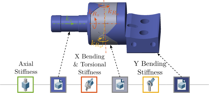
The detailed mechanical design of the active platform, depicted in Figure ref:fig:detail_design_nano_hexapod_elements, is presented in this section. Several primary objectives guided the mechanical design. First, to ensure a well-defined Jacobian matrix used in the control architecture, accurate positioning of the top flexible joint rotation points and correct orientation of the struts were required. Secondly, space constraints necessitated that the entire platform fit within a cylinder with a radius of $120\,\text{mm}$ and a height of $95\,\text{mm}$. Thirdly, because performance predicted by the multi-body model was fulfilling the requirements, the final design was intended to approximate the behavior of this "idealized" active platform as closely as possible. This objective implies that the frequencies of (un-modelled) flexible modes potentially detrimental to control performance needed to be maximized. Finally, considerations for ease of mounting, alignment, and maintenance were incorporated, specifically ensuring that struts could be easily replaced in the event of failure.
Mechanical Design
<<sec:detail_design_mechanics>>
Struts
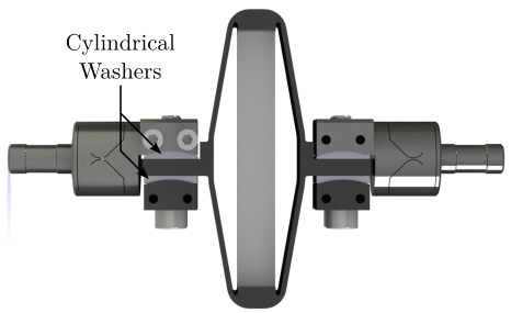
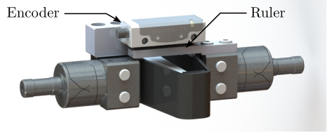
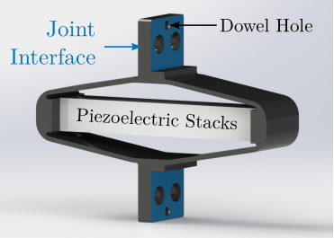
The strut design, illustrated in Figure ref:fig:detail_design_strut, was driven by several factors. Stiff interfaces were required between the amplified piezoelectric actuator and the two flexible joints, as well as between the flexible joints and their respective mounting plates. Due to the limited angular stroke of the flexible joints, it was critical that the struts could be assembled such that the two cylindrical interfaces were coaxial while the flexible joints remained in their unstressed, nominal rest position. To facilitate this alignment, cylindrical washers (Figure ref:fig:detail_design_strut_without_enc) were integrated into the design to compensate for potential deviations from perfect flatness between the two APA interface planes (Figure ref:fig:detail_design_apa). Furthermore, a dedicated mounting bench was developed to enable precise alignment of each strut, even when accounting for typical machining inaccuracies. The mounting procedure is described in Section ref:sec:test_struts_mounting. Lastly, the design needed to permit the fixation of an encoder parallel to the strut axis, as shown in Figure ref:fig:detail_design_strut_with_enc.
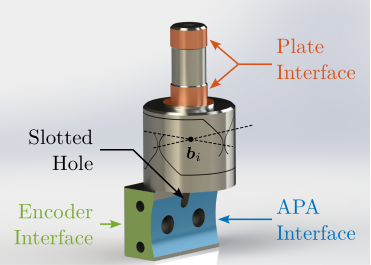
The flexible joints, shown in Figure ref:fig:detail_design_flexible_joint, were manufactured using wire-cut electrical discharge machining (EDM). First, the part's inherent fragility, stemming from its $0.25\,\text{mm}$ neck dimension, makes it susceptible to damage from cutting forces typical in classical machining. Furthermore, wire-cut EDM allows for the very tight machining tolerances critical for achieving accurate location of the center of rotation relative to the plate interfaces (indicated by red surfaces in Figure ref:fig:detail_design_flexible_joint) and for maintaining the correct neck dimensions necessary for the desired stiffness and angular stroke properties. The material chosen for the flexible joints is a stainless steel designated X5CrNiCuNb16-4 (alternatively known as F16Ph). This selection was based on its high specified yield strength (exceeding $1\,\text{GPa}$ after appropriate heat treatment) and its high fatigue resistance.
As shown in Figure ref:fig:detail_design_flexible_joint, the interface designed to connect with the APA possesses a cylindrical shape, facilitating the use of the aforementioned cylindrical washers for alignment. A slotted hole was incorporated to permit alignment of the flexible joint with the APA via a dowel pin. Additionally, two threaded holes were included on the sides for mounting the encoder components. The interface connecting the flexible joint to the platform plates will be described subsequently.
Modifications to the standard mechanical interfaces of the APA300ML were requested from the manufacturer. The modified design features two planar surfaces and a dowel hole for precise location and orientation, as illustrated in Figure ref:fig:detail_design_apa.
Accurate measurement of the relative displacement within each strut requires the encoders to sense the motion between the rotational centers of the two associated flexible joints. To achieve this, two interface parts, fabricated from aluminum, were designed. These parts serve to fix the encoder head and the associated scale (ruler) to the two flexible joints, as depicted in Figure ref:fig:detail_design_strut_with_enc.
Plates
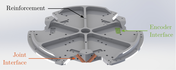
The design of the top and bottom plates of the active platform was governed by two main requirements: maximizing the frequency of flexible modes and ensuring accurate positioning of the top flexible joints and well-defined orientation of the struts. To maximize the natural frequencies associated with plate flexibility, a network of reinforcing ribs was incorporated into the design, as shown for the top plate in Figure ref:fig:detail_design_top_plate. Although topology optimization methods were considered, the implemented ribbed design was found to provide sufficiently high natural frequencies for the flexible modes.
The interfaces for the joints on the plates incorporate V-grooves (red planes in Figure ref:fig:detail_design_top_plate). The cylindrical portion of each flexible joint is constrained within its corresponding V-groove through two distinct line contacts, illustrated in Figure ref:fig:detail_design_fixation_flexible_joints. These grooves consequently serve to define the nominal orientation of the struts. High machining accuracy for these features is essential to ensure that the flexible joints are in their neutral, unstressed state when the active platform is assembled.
Furthermore, the flat interface surface of each top flexible joint is designed to be in direct contact with the top platform surface, as shown in Figure ref:fig:detail_design_location_top_flexible_joints. This contact ensures that the centers of rotation of the top flexible joints, are precisely located relative to the top platform coordinate system. The bottom flexible joints, however, are primarily oriented by the V-grooves without the same precise positional constraint against the bottom plate, as shown in Figure ref:fig:detail_design_location_bot_flex.
Both plates were specified to be manufactured from a martensitic stainless steel, X30Cr13. This material was selected primarily for its high hardness, which minimizes the risk of deformation of the reference surfaces during the clamping of the flexible joints. This characteristic is expected to permit repeated assembly and disassembly of the struts, should maintenance or reconfiguration be necessary.
Finite Element Analysis
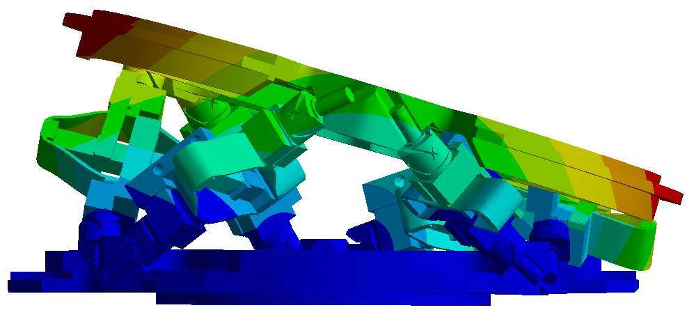
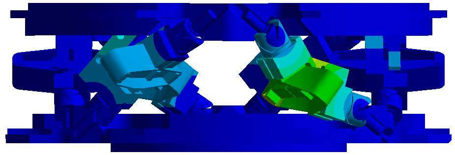
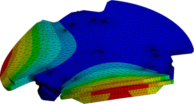
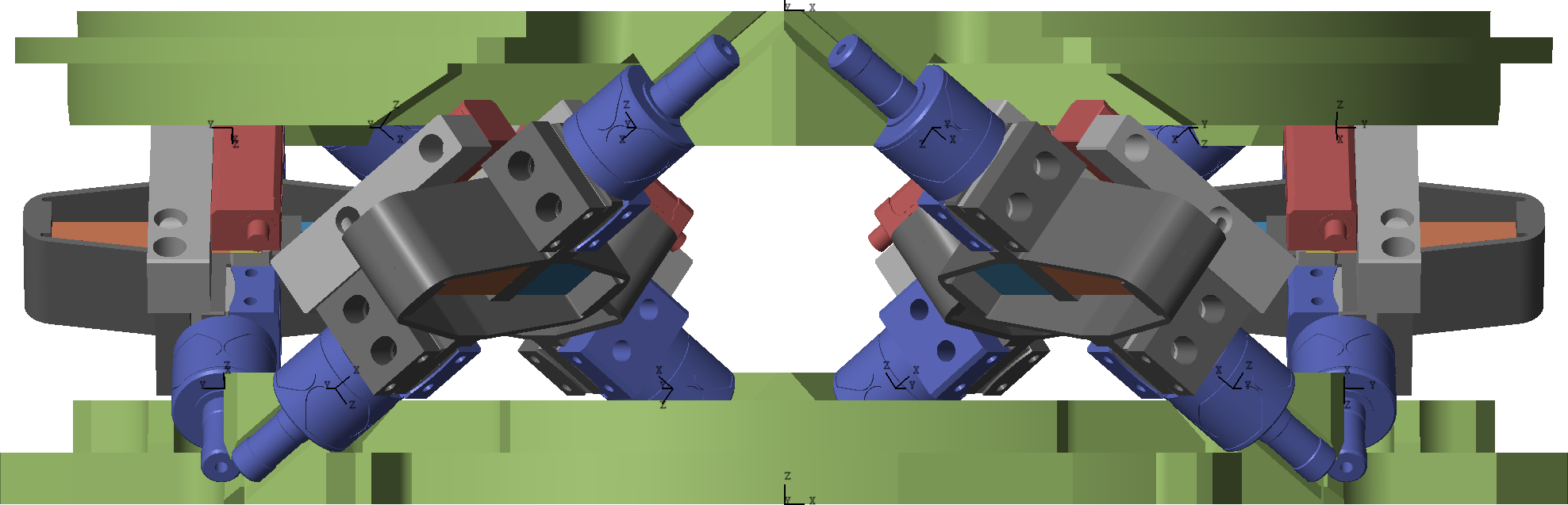
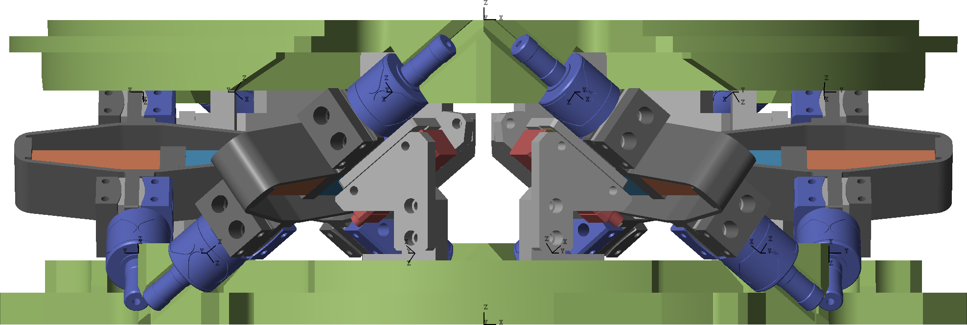
A finite element analysis (FEA) of the complete active platform assembly was performed to identify modes that could potentially affect performance. The analysis revealed that the first six modes correspond to "suspension" modes, where the top plate effectively moves as a rigid body, and motion primarily involves axial displacement of the six struts (an example is shown in Figure ref:fig:detail_design_fem_rigid_body_mode). Following these suspension modes, numerous "local" modes associated with the struts themselves were observed in the frequency range between $205\,\text{Hz}$ and $420\,\text{Hz}$. One such mode is represented in Figure ref:fig:detail_design_fem_strut_mode. Although these modes do not appear to induce significant motion of the top platform, they do cause relative displacement between the encoder components (head and scale) mounted on the strut. Consequently, such modes could potentially degrade control performance if the active platform's position is regulated using these encoder measurements. The extent to which these modes might be detrimental is difficult to establish at this stage, as it depends on whether they are significantly excited by the APA actuation and their sensitivity to strut alignment. Finally, the FEA indicated that flexible modes of the top plate itself begin to appear at frequencies above $650\,\text{Hz}$, with the first such mode shown in Figure ref:fig:detail_design_fem_plate_mode.
Alternative Encoder Placement
In anticipation of potential issues arising from the local modes of the struts affecting encoder measurements, an alternative fixation strategy for the encoders was designed. In this configuration, the encoders are fixed directly to the top and bottom plates instead of the struts, as illustrated in Figure ref:fig:detail_design_enc_plates_design.
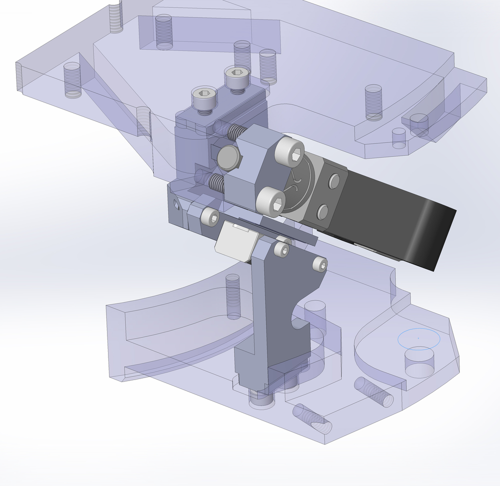
Dedicated supports, machined from aluminum, were designed for this purpose. It was verified through FEA that the natural modes of these supports occur at frequencies sufficiently high (first mode estimated at $1120\,\text{Hz}$) to not be problematic for control. Precise positioning of these encoder supports is achieved through machined pockets in both the top and bottom plates, visible in Figure ref:fig:detail_design_top_plate (indicated in green). Although the encoders in this arrangement are aligned parallel to the nominal strut axes, they no longer measure the exact relative displacement along the strut between the flexible joint centers. This geometric discrepancy implies that if the relative motion control of the active platform is based directly on these encoder readings, the kinematic calculations may be slightly inaccurate, potentially affecting the overall positioning accuracy of the platform.
Multi-Body Model
<<sec:detail_design_model>>
Introduction ignore
Prior to the procurement of mechanical components, the multi-body simulation model of the active platform was refined to incorporate the finalized design geometries. Two distinct configurations, corresponding to the two encoder mounting strategies discussed previously, were considered in the model, as displayed in Figure ref:fig:detail_design_simscape_encoder: one with encoders fixed to the struts, and another with encoders fixed to the plates. In these models, the top and bottom plates were represented as rigid bodies, with their inertial properties calculated directly from the 3D CAD geometry.
Flexible Joints
Several levels of detail were considered for modeling the flexible joints within the multi-body model. Models with two degrees of freedom incorporating only bending stiffnesses, models with three degrees of freedom adding torsional stiffness, and models with four degrees of freedom further adding axial stiffness were evaluated. The multi-body representation corresponding to the 4DoF configuration is shown in Figure ref:fig:detail_design_simscape_model_flexible_joint. This model is composed of three distinct solid bodies interconnected by joints, whose stiffness properties were derived from finite element analysis of the joint component.
Amplified Piezoelectric Actuators
The amplified piezoelectric actuators (APAs) were incorporated into the multi-body model following the methodology detailed in Section ref:sec:detail_fem_actuator. Two distinct representations of the APA can be utilized within the simulation: a simplified 2DoF model capturing the axial behavior, or a more complex "Reduced Order Flexible Body" model derived from a finite element model.
Encoders
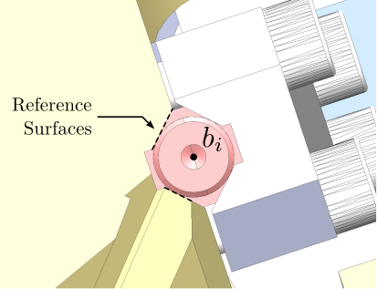
In earlier modeling stages, the relative displacement sensors (encoders) were implemented as a direct measurement of the relative distance between the joint connection points $\bm{a}_i$ and $\bm{b}_i$. However, as indicated by the FEA results discussed previously, the flexible modes inherent to the struts could potentially affect the encoder measurement. Therefore, a more sophisticated model of the optical encoder was necessary.
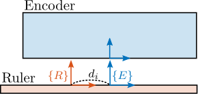
The optical encoders operate based on the interaction between an encoder head and a graduated scale or ruler. The optical encoder head contains a light source that illuminates the ruler. A reference frame $\{E\}$ fixed to the scale, represents the the light position on the scale, as illustrated in Figure ref:fig:detail_design_simscape_encoder_model. The ruler features a precise grating pattern (in this case, with a $20\,\mu m$ pitch), and its position is associated with the reference frame $\{R\}$. The displacement measured by the encoder corresponds to the relative position of the encoder frame $\{E\}$ (specifically, the point where the light interacts with the scale) with respect to the ruler frame $\{R\}$, projected along the measurement direction defined by the scale.
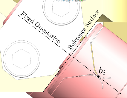
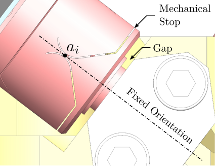
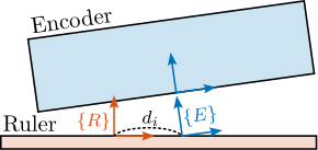
An important consequence of this measurement principle is that a relative rotation between the encoder head and the ruler, as depicted conceptually in Figure ref:fig:detail_design_simscape_encoder_disp, can induce a measured displacement.
Validation of the designed active platform
The refined multi-body model of the active platform was integrated into the multi-body micro-station model. Dynamical analysis was performed, confirming that the platform's behavior closely approximates the dynamics of the "idealized" model used during the conceptual design phase. Consequently, closed-loop performance simulations replicating tomography experiments yielded metrics highly comparable to those previously predicted (as presented in Section ref:ssec:nass_hac_tomography). Given this similarity and because analogous simulations are conducted and detailed during the experimental validation phase (Section ref:sec:test_id31_hac), these specific results are not reiterated here.