20 KiB
Measurement of Piezoelectric Amplifiers
- Introduction
- Effect of a change of capacitance
- Effect of a change in Voltage level
- Comparison PI / Cedrat
- Impedance Measurement
- New PI amplifier measurements
Introduction ignore
Effect of a change of capacitance
Cedrat Technology
Load Data
  piezo1 = load('mat/cedrat_la75b_med_1_stack.mat', 't', 'V_in', 'V_out');
  piezo2 = load('mat/cedrat_la75b_med_2_stack.mat', 't', 'V_in', 'V_out');
  piezo3 = load('mat/cedrat_la75b_med_3_stack.mat', 't', 'V_in', 'V_out');
Compute Coherence and Transfer functions
  Ts = 1e-4;
  win = hann(ceil(0.1/Ts));

  [tf_1, f] = tfestimate(piezo1.V_in, piezo1.V_out, win, [], [], 1/Ts);
  [co_1, ~] = mscohere(piezo1.V_in, piezo1.V_out, win, [], [], 1/Ts);

  [tf_2, ~] = tfestimate(piezo2.V_in, piezo2.V_out, win, [], [], 1/Ts);
  [co_2, ~] = mscohere(piezo2.V_in, piezo2.V_out, win, [], [], 1/Ts);

  [tf_3, ~] = tfestimate(piezo3.V_in, piezo3.V_out, win, [], [], 1/Ts);
  [co_3, ~] = mscohere(piezo3.V_in, piezo3.V_out, win, [], [], 1/Ts);
We remove the phase delay due to the time delay of the ADC/DAC:
angle_delay = 180/pi*angle(squeeze(freqresp(exp(-s*Ts), f, 'Hz')));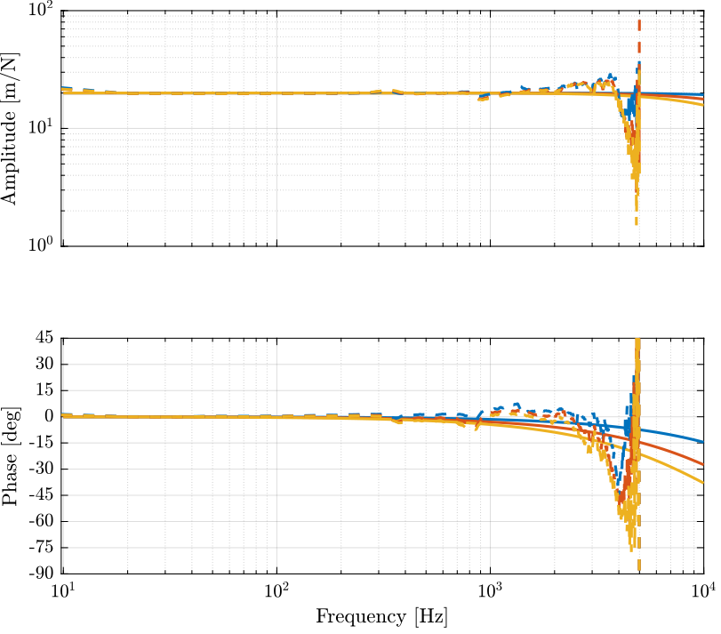
PI
  piezo1 = load('mat/pi_505_high.mat', 't', 'V_in', 'V_out');
  piezo2 = load('mat/pi_505_high_2_stacks.mat', 't', 'V_in', 'V_out');
  piezo3 = load('mat/pi_505_high_3_stacks.mat', 't', 'V_in', 'V_out');
Ts = 1e-4;
win = hann(ceil(0.1/Ts));
[tf_1, f] = tfestimate(piezo1.V_in, piezo1.V_out, win, [], [], 1/Ts);
[co_1, ~] = mscohere(piezo1.V_in, piezo1.V_out, win, [], [], 1/Ts);
[tf_2, ~] = tfestimate(piezo2.V_in, piezo2.V_out, win, [], [], 1/Ts);
[co_2, ~] = mscohere(piezo2.V_in, piezo2.V_out, win, [], [], 1/Ts);
[tf_3, ~] = tfestimate(piezo3.V_in, piezo3.V_out, win, [], [], 1/Ts);
[co_3, ~] = mscohere(piezo3.V_in, piezo3.V_out, win, [], [], 1/Ts);We remove the phase delay due to the time delay of the ADC/DAC:
angle_delay = 180/pi*angle(squeeze(freqresp(exp(-s*Ts), f, 'Hz')));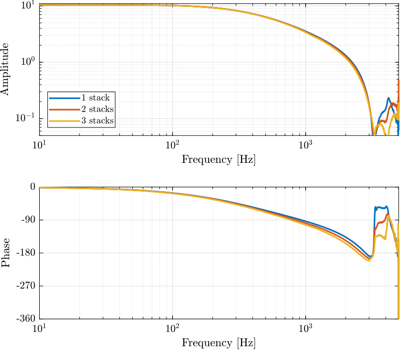
Effect of a change in Voltage level
Cedrat Technology
  hi = load('mat/cedrat_la75b_high_1_stack.mat', 't', 'V_in', 'V_out');
  me = load('mat/cedrat_la75b_med_1_stack.mat', 't', 'V_in', 'V_out');
  lo = load('mat/cedrat_la75b_low_1_stack.mat', 't', 'V_in', 'V_out');
Ts = 1e-4;
win = hann(ceil(0.1/Ts));
[tf_hi, f] = tfestimate(hi.V_in, hi.V_out, win, [], [], 1/Ts);
[co_hi, ~] = mscohere(hi.V_in, hi.V_out, win, [], [], 1/Ts);
[tf_me, ~] = tfestimate(me.V_in, me.V_out, win, [], [], 1/Ts);
[co_me, ~] = mscohere(me.V_in, me.V_out, win, [], [], 1/Ts);
[tf_lo, ~] = tfestimate(lo.V_in, lo.V_out, win, [], [], 1/Ts);
[co_lo, ~] = mscohere(lo.V_in, lo.V_out, win, [], [], 1/Ts);We remove the phase delay due to the time delay of the ADC/DAC:
angle_delay = 180/pi*angle(squeeze(freqresp(exp(-s*Ts), f, 'Hz')));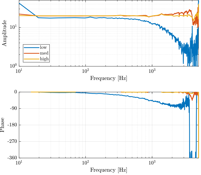
PI
  hi = load('mat/pi_505_high.mat', 't', 'V_in', 'V_out');
  lo = load('mat/pi_505_low.mat', 't', 'V_in', 'V_out');
Ts = 1e-4;
win = hann(ceil(0.1/Ts));
[tf_hi, f] = tfestimate(hi.V_in, hi.V_out, win, [], [], 1/Ts);
[co_hi, ~] = mscohere(hi.V_in, hi.V_out, win, [], [], 1/Ts);
[tf_lo, ~] = tfestimate(lo.V_in, lo.V_out, win, [], [], 1/Ts);
[co_lo, ~] = mscohere(lo.V_in, lo.V_out, win, [], [], 1/Ts);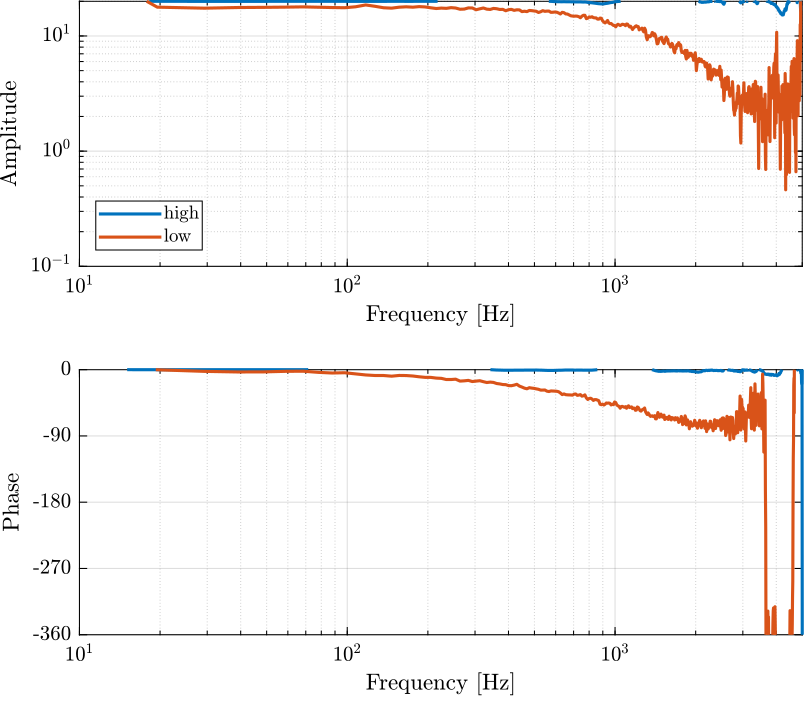
Comparison PI / Cedrat
Results
  ce_results = load('mat/cedrat_la75b_high_1_stack.mat', 't', 'V_in', 'V_out');
  pi_results = load('mat/pi_505_high.mat', 't', 'V_in', 'V_out');
Ts = 1e-4;
win = hann(ceil(0.1/Ts));
[tf_ce, f] = tfestimate(ce_results.V_in, ce_results.V_out, win, [], [], 1/Ts);
[tf_pi, ~] = tfestimate(pi_results.V_in, pi_results.V_out, win, [], [], 1/Ts);We remove the phase delay due to the time delay of the ADC/DAC:
angle_delay = 180/pi*angle(squeeze(freqresp(exp(-s*Ts), f, 'Hz')));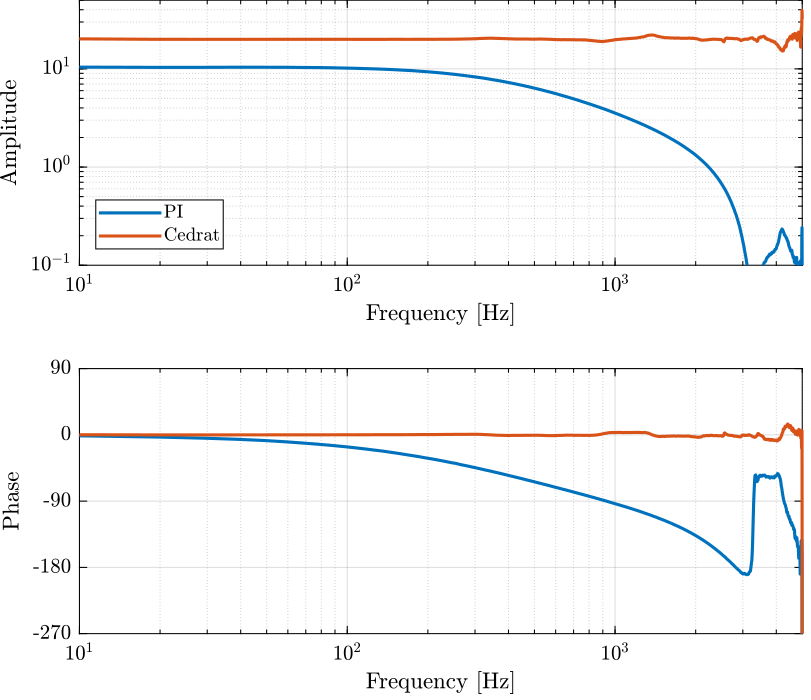
Impedance Measurement
Introduction ignore
The goal is to experimentally measure the output impedance of the voltage amplifiers.
To do so, the output voltage is first measure without any load ($V$). It is then measure when a 10Ohm load is used ($V^\prime$).
The load ($R = 10\Omega$) and the internal resistor ($R_i$) form a voltage divider, and thus: \[ V^\prime = \frac{R}{R + R_i} V \]
From the two values of voltage, the internal resistor value can be computed: \[ R_i = R \frac{V - V^\prime}{V^\prime} \]
Cedrat Technology
Compute Impedance
  R = 10;    % Resistive Load used [Ohm]
  V = 0.998; % Output Voltage without any load [V]
  Vp = 0.912; % Output Voltage with resistice load [V]
R * (V - Vp)/Vp;0.94298
  R = 47;    % Resistive Load used [Ohm]
  V = 4.960; % Output Voltage without any load [V]
  Vp = 4.874; % Output Voltage with resistice load [V]
R * (V - Vp)/Vp;0.8293
Effect of Impedance on the phase drop
  C_1 = 5e-6; % Capacitance in [F]
  C_2 = 10e-6; % Capacitance in [F]
  C_3 = 15e-6; % Capacitance in [F]

  Ri = R * (V - Vp)/Vp; % Internal resistance [Ohm]
  G0 = 20;

  G_1 = G0/(1+Ri*C_1*s);
  G_2 = G0/(1+Ri*C_2*s);
  G_3 = G0/(1+Ri*C_3*s);
PI
  R = 10;    % Resistive Load used [Ohm]
  V = 1.059; % Output Voltage without any load [V]
  Vp = 0.828; % Output Voltage with resistice load [V]
R * (V - Vp)/Vp2.7899
  R = 10;    % Resistive Load used [Ohm]
  V = 2.092; % Output Voltage without any load [V]
  Vp = 1.637; % Output Voltage with resistice load [V]
R * (V - Vp)/Vp2.7795
New PI amplifier measurements
PI
Three measurements are done:
- Slew Rate limitation at maximum
- Slew Rate limitation at minimum
- Notch Filter at maximum frequency
  pi_sr_min = load('mat/pi_slew_rate_min.mat');
  pi_sr_max = load('mat/pi_slew_rate_max.mat');
  pi_sr_max_notch = load('mat/pi_slew_rate_max_notch_high.mat');
Ts = 1e-4;
win = hann(ceil(0.1/Ts));
[tf_sr_min, f] = tfestimate(pi_sr_min.V_in, pi_sr_min.V_out, win, [], [], 1/Ts);
[tf_sr_max, ~] = tfestimate(pi_sr_max.V_in, pi_sr_max.V_out, win, [], [], 1/Ts);
[tf_sr_max_notch, ~] = tfestimate(pi_sr_max_notch.V_in, pi_sr_max_notch.V_out, win, [], [], 1/Ts); angle_delay = 180/pi*angle(squeeze(freqresp(exp(-s*Ts), f, 'Hz')));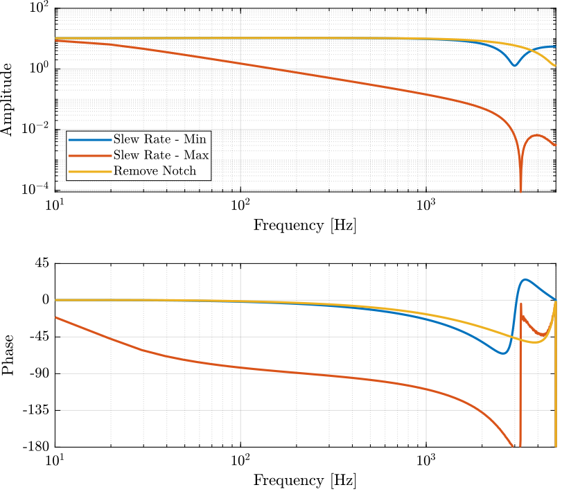
Transfer function of the Voltage Amplifier
The identified transfer function still seems to match the one of a notch filter at 5kHz.
  w_nf = 2*pi*5e3; % Notch Filter Frequency [rad/s]
  G = 10.5*(s^2 + 2*w_nf*0.12*s + w_nf^2)/(s^2 + 2*w_nf*s + w_nf^2);