17 KiB
Cubic configuration for the Stewart Platform
- Introduction
- Configuration Analysis - Stiffness Matrix
- Cubic Stewart platform centered with the cube center - Jacobian estimated at the cube center
- Cubic Stewart platform centered with the cube center - Jacobian not estimated at the cube center
- Cubic Stewart platform not centered with the cube center - Jacobian estimated at the cube center
- Cubic Stewart platform not centered with the cube center - Jacobian estimated at the Stewart platform center
- Conclusion
- Cubic size analysis
- Functions
- Bibliography
Introduction ignore
The discovery of the Cubic configuration is done in cite:geng94_six_degree_of_freed_activ. Further analysis is conducted in
The specificity of the Cubic configuration is that each actuator is orthogonal with the others.
The cubic (or orthogonal) configuration of the Stewart platform is now widely used (cite:preumont07_six_axis_singl_stage_activ,jafari03_orthog_gough_stewar_platf_microm).
According to cite:preumont07_six_axis_singl_stage_activ, the cubic configuration provides a uniform stiffness in all directions and minimizes the crosscoupling from actuator to sensor of different legs (being orthogonal to each other).
To generate and study the Cubic configuration, generateCubicConfiguration is used (description in section sec:generateCubicConfiguration).
The goal is to study the benefits of using a cubic configuration:
- Equal stiffness in all the degrees of freedom?
- No coupling between the actuators?
- Is the center of the cube an important point?
TODO Configuration Analysis - Stiffness Matrix
Cubic Stewart platform centered with the cube center - Jacobian estimated at the cube center
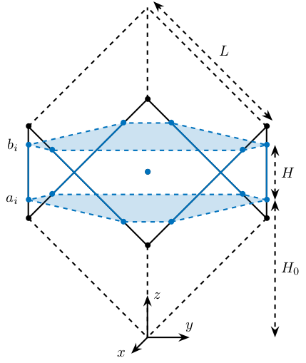
We create a cubic Stewart platform (figure fig:3d-cubic-stewart-aligned) in such a way that the center of the cube (black dot) is located at the center of the Stewart platform (blue dot). The Jacobian matrix is estimated at the location of the center of the cube.

  opts = struct(...
      'H_tot', 100, ... % Total height of the Hexapod [mm]
      'L',     200/sqrt(3), ... % Size of the Cube [mm]
      'H',     60, ... % Height between base joints and platform joints [mm]
      'H0',    200/2-60/2 ... % Height between the corner of the cube and the plane containing the base joints [mm]
      );
  stewart = initializeCubicConfiguration(opts);
  opts = struct(...
      'Jd_pos', [0, 0, -50], ... % Position of the Jacobian for displacement estimation from the top of the mobile platform [mm]
      'Jf_pos', [0, 0, -50]  ... % Position of the Jacobian for force location from the top of the mobile platform [mm]
      );
  stewart = computeGeometricalProperties(stewart, opts);

  save('./mat/stewart.mat', 'stewart');
K = stewart.Jf'*stewart.Jf;| 2 | 1.9e-18 | -2.3e-17 | 1.8e-18 | 5.5e-17 | -1.5e-17 |
| 1.9e-18 | 2 | 6.8e-18 | -6.1e-17 | -1.6e-18 | 4.8e-18 |
| -2.3e-17 | 6.8e-18 | 2 | -6.7e-18 | 4.9e-18 | 5.3e-19 |
| 1.8e-18 | -6.1e-17 | -6.7e-18 | 0.0067 | -2.3e-20 | -6.1e-20 |
| 5.5e-17 | -1.6e-18 | 4.9e-18 | -2.3e-20 | 0.0067 | 1e-18 |
| -1.5e-17 | 4.8e-18 | 5.3e-19 | -6.1e-20 | 1e-18 | 0.027 |
Cubic Stewart platform centered with the cube center - Jacobian not estimated at the cube center
We create a cubic Stewart platform with center of the cube located at the center of the Stewart platform (figure fig:3d-cubic-stewart-aligned). The Jacobian matrix is not estimated at the location of the center of the cube.
  opts = struct(...
      'H_tot', 100, ... % Total height of the Hexapod [mm]
      'L',     200/sqrt(3), ... % Size of the Cube [mm]
      'H',     60, ... % Height between base joints and platform joints [mm]
      'H0',    200/2-60/2 ... % Height between the corner of the cube and the plane containing the base joints [mm]
      );
  stewart = initializeCubicConfiguration(opts);
  opts = struct(...
      'Jd_pos', [0, 0, 0], ... % Position of the Jacobian for displacement estimation from the top of the mobile platform [mm]
      'Jf_pos', [0, 0, 0]  ... % Position of the Jacobian for force location from the top of the mobile platform [mm]
      );
  stewart = computeGeometricalProperties(stewart, opts);
K = stewart.Jf'*stewart.Jf;| 2 | 1.9e-18 | -2.3e-17 | 1.5e-18 | -0.1 | -1.5e-17 |
| 1.9e-18 | 2 | 6.8e-18 | 0.1 | -1.6e-18 | 4.8e-18 |
| -2.3e-17 | 6.8e-18 | 2 | -5.1e-19 | -5.5e-18 | 5.3e-19 |
| 1.5e-18 | 0.1 | -5.1e-19 | 0.012 | -3e-19 | 3.1e-19 |
| -0.1 | -1.6e-18 | -5.5e-18 | -3e-19 | 0.012 | 1.9e-18 |
| -1.5e-17 | 4.8e-18 | 5.3e-19 | 3.1e-19 | 1.9e-18 | 0.027 |
Cubic Stewart platform not centered with the cube center - Jacobian estimated at the cube center
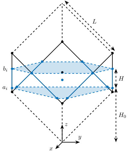
Here, the "center" of the Stewart platform is not at the cube center (figure fig:3d-cubic-stewart-misaligned). The Jacobian is estimated at the cube center.

The center of the cube is at $z = 110$. The Stewart platform is from $z = H_0 = 75$ to $z = H_0 + H_{tot} = 175$. The center height of the Stewart platform is then at $z = \frac{175-75}{2} = 50$. The center of the cube from the top platform is at $z = 110 - 175 = -65$.
  opts = struct(...
      'H_tot', 100,         ... % Total height of the Hexapod [mm]
      'L',     220/sqrt(3), ... % Size of the Cube [mm]
      'H',     60,          ... % Height between base joints and platform joints [mm]
      'H0',    75           ... % Height between the corner of the cube and the plane containing the base joints [mm]
      );
  stewart = initializeCubicConfiguration(opts);
  opts = struct(...
      'Jd_pos', [0, 0, -65], ... % Position of the Jacobian for displacement estimation from the top of the mobile platform [mm]
      'Jf_pos', [0, 0, -65]  ... % Position of the Jacobian for force location from the top of the mobile platform [mm]
      );
  stewart = computeGeometricalProperties(stewart, opts);
K = stewart.Jf'*stewart.Jf;| 2 | -1.8e-17 | 2.6e-17 | 3.3e-18 | 0.04 | 1.7e-19 |
| -1.8e-17 | 2 | 1.9e-16 | -0.04 | 2.2e-19 | -5.3e-19 |
| 2.6e-17 | 1.9e-16 | 2 | -8.9e-18 | 6.5e-19 | -5.8e-19 |
| 3.3e-18 | -0.04 | -8.9e-18 | 0.0089 | -9.3e-20 | 9.8e-20 |
| 0.04 | 2.2e-19 | 6.5e-19 | -9.3e-20 | 0.0089 | -2.4e-18 |
| 1.7e-19 | -5.3e-19 | -5.8e-19 | 9.8e-20 | -2.4e-18 | 0.032 |
We obtain $k_x = k_y = k_z$ and $k_{\theta_x} = k_{\theta_y}$, but the Stiffness matrix is not diagonal.
Cubic Stewart platform not centered with the cube center - Jacobian estimated at the Stewart platform center
Here, the "center" of the Stewart platform is not at the cube center. The Jacobian is estimated at the center of the Stewart platform.
The center of the cube is at $z = 110$. The Stewart platform is from $z = H_0 = 75$ to $z = H_0 + H_{tot} = 175$. The center height of the Stewart platform is then at $z = \frac{175-75}{2} = 50$. The center of the cube from the top platform is at $z = 110 - 175 = -65$.
  opts = struct(...
      'H_tot', 100, ... % Total height of the Hexapod [mm]
      'L',     220/sqrt(3), ... % Size of the Cube [mm]
      'H',     60, ... % Height between base joints and platform joints [mm]
      'H0',    75 ... % Height between the corner of the cube and the plane containing the base joints [mm]
      );
  stewart = initializeCubicConfiguration(opts);
  opts = struct(...
      'Jd_pos', [0, 0, -60], ... % Position of the Jacobian for displacement estimation from the top of the mobile platform [mm]
      'Jf_pos', [0, 0, -60]  ... % Position of the Jacobian for force location from the top of the mobile platform [mm]
      );
  stewart = computeGeometricalProperties(stewart, opts);
K = stewart.Jf'*stewart.Jf;| 2 | -1.8e-17 | 2.6e-17 | -5.7e-19 | 0.03 | 1.7e-19 |
| -1.8e-17 | 2 | 1.9e-16 | -0.03 | 2.2e-19 | -5.3e-19 |
| 2.6e-17 | 1.9e-16 | 2 | -1.5e-17 | 6.5e-19 | -5.8e-19 |
| -5.7e-19 | -0.03 | -1.5e-17 | 0.0085 | 4.9e-20 | 1.7e-19 |
| 0.03 | 2.2e-19 | 6.5e-19 | 4.9e-20 | 0.0085 | -1.1e-18 |
| 1.7e-19 | -5.3e-19 | -5.8e-19 | 1.7e-19 | -1.1e-18 | 0.032 |
We obtain $k_x = k_y = k_z$ and $k_{\theta_x} = k_{\theta_y}$, but the Stiffness matrix is not diagonal.
Conclusion
- The cubic configuration permits to have $k_x = k_y = k_z$ and $k_{\theta\x} = k_{\theta_y}$
- The stiffness matrix $K$ is diagonal for the cubic configuration if the Stewart platform and the cube are centered and the Jacobian is estimated at the cube center
TODO Cubic size analysis
We here study the effect of the size of the cube used for the Stewart configuration.
We fix the height of the Stewart platform, the center of the cube is at the center of the Stewart platform.
We only vary the size of the cube.
  H_cubes = 250:20:350;
  stewarts = {zeros(length(H_cubes), 1)};
for i = 1:length(H_cubes)
H_cube = H_cubes(i);
H_tot = 100;
H = 80;
opts = struct(...
'H_tot', H_tot, ... % Total height of the Hexapod [mm]
'L', H_cube/sqrt(3), ... % Size of the Cube [mm]
'H', H, ... % Height between base joints and platform joints [mm]
'H0', H_cube/2-H/2 ... % Height between the corner of the cube and the plane containing the base joints [mm]
);
stewart = initializeCubicConfiguration(opts);
opts = struct(...
'Jd_pos', [0, 0, H_cube/2-opts.H0-opts.H_tot], ... % Position of the Jacobian for displacement estimation from the top of the mobile platform [mm]
'Jf_pos', [0, 0, H_cube/2-opts.H0-opts.H_tot] ... % Position of the Jacobian for force location from the top of the mobile platform [mm]
);
stewart = computeGeometricalProperties(stewart, opts);
stewarts(i) = {stewart};
endThe Stiffness matrix is computed for all generated Stewart platforms.
  Ks = zeros(6, 6, length(H_cube));
  for i = 1:length(H_cubes)
    Ks(:, :, i) = stewarts{i}.Jd'*stewarts{i}.Jd;
  end
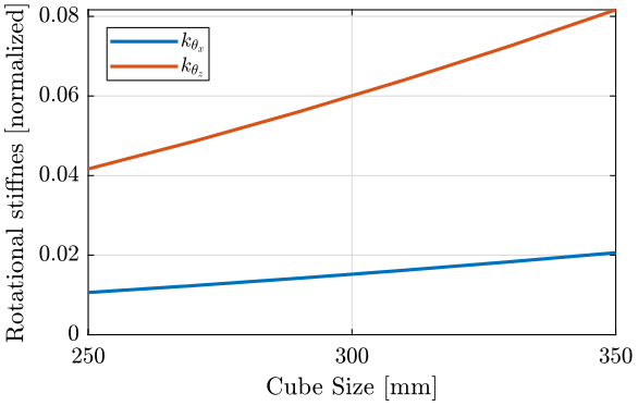
The only elements of $K$ that vary are $k_{\theta_x} = k_{\theta_y}$ and $k_{\theta_z}$.
Finally, we plot $k_{\theta_x} = k_{\theta_y}$ and $k_{\theta_z}$
  figure;
  hold on;
  plot(H_cubes, squeeze(Ks(4, 4, :)), 'DisplayName', '$k_{\theta_x}$');
  plot(H_cubes, squeeze(Ks(6, 6, :)), 'DisplayName', '$k_{\theta_z}$');
  hold off;
  legend('location', 'northwest');
xlabel('Cube Size [mm]'); ylabel('Rotational stiffnes [normalized]'); <<plt-matlab>>We observe that $k_{\theta_x} = k_{\theta_y}$ and $k_{\theta_z}$ increase linearly with the cube size.
In order to maximize the rotational stiffness of the Stewart platform, the size of the cube should be the highest possible. In that case, the legs will the further separated. Size of the cube is then limited by allowed space.
Functions
<<sec:functions>>
generateCubicConfiguration: Generate a Cubic Configuration
<<sec:generateCubicConfiguration>>
This Matlab function is accessible here.
Function description
  function [stewart] = generateCubicConfiguration(stewart, args)
  % generateCubicConfiguration - Generate a Cubic Configuration
  %
  % Syntax: [stewart] = generateCubicConfiguration(stewart, args)
  %
  % Inputs:
  %    - stewart - A structure with the following fields
  %        - H   [1x1] - Total height of the platform [m]
  %    - args - Can have the following fields:
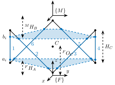
  %        - Hc  [1x1] - Height of the "useful" part of the cube [m]
  %        - FOc [1x1] - Height of the center of the cube with respect to {F} [m]
  %        - FHa [1x1] - Height of the plane joining the points ai with respect to the frame {F} [m]
  %        - MHb [1x1] - Height of the plane joining the points bi with respect to the frame {M} [m]
  %
  % Outputs:
  %    - stewart - updated Stewart structure with the added fields:
  %        - Fa  [3x6] - Its i'th column is the position vector of joint ai with respect to {F}
% - Mb [3x6] - Its i'th column is the position vector of joint bi with respect to {M}Optional Parameters
  arguments
      stewart
      args.Hc  (1,1) double {mustBeNumeric, mustBePositive} = 60e-3
      args.FOc (1,1) double {mustBeNumeric} = 50e-3
      args.FHa (1,1) double {mustBeNumeric, mustBePositive} = 15e-3
      args.MHb (1,1) double {mustBeNumeric, mustBePositive} = 15e-3
  end
Position of the Cube
We define the useful points of the cube with respect to the Cube's center. ${}^{C}C$ are the 6 vertices of the cubes expressed in a frame {C} which is located at the center of the cube and aligned with {F} and {M}.
  sx = [ 2; -1; -1];
  sy = [ 0;  1; -1];
  sz = [ 1;  1;  1];

  R = [sx, sy, sz]./vecnorm([sx, sy, sz]);

  L = args.Hc*sqrt(3);

  Cc = R'*[[0;0;L],[L;0;L],[L;0;0],[L;L;0],[0;L;0],[0;L;L]] - [0;0;1.5*args.Hc];

  CCf = [Cc(:,1), Cc(:,3), Cc(:,3), Cc(:,5), Cc(:,5), Cc(:,1)]; % CCf(:,i) corresponds to the bottom cube's vertice corresponding to the i'th leg
  CCm = [Cc(:,2), Cc(:,2), Cc(:,4), Cc(:,4), Cc(:,6), Cc(:,6)]; % CCm(:,i) corresponds to the top cube's vertice corresponding to the i'th leg
Compute the pose
We can compute the vector of each leg ${}^{C}\hat{\bm{s}}_{i}$ (unit vector from ${}^{C}C_{f}$ to ${}^{C}C_{m}$).
CSi = (CCm - CCf)./vecnorm(CCm - CCf);We now which to compute the position of the joints $a_{i}$ and $b_{i}$.
  stewart.Fa = CCf + [0; 0; args.FOc] + ((args.FHa-(args.FOc-args.Hc/2))./CSi(3,:)).*CSi;
  stewart.Mb = CCf + [0; 0; args.FOc-stewart.H] + ((stewart.H-args.MHb-(args.FOc-args.Hc/2))./CSi(3,:)).*CSi;
Bibliography ignore
bibliographystyle:unsrtnat bibliography:ref.bib

