38 KiB
Nano-Hexapod - Test Bench
- Introduction
- Encoders fixed to the Struts
- Encoders fixed to the plates
This report is also available as a pdf.
Introduction ignore
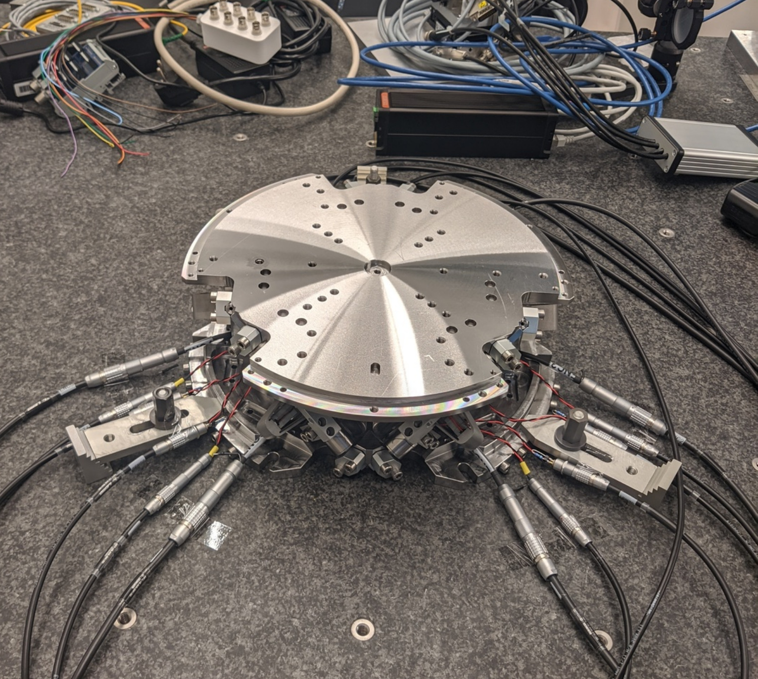
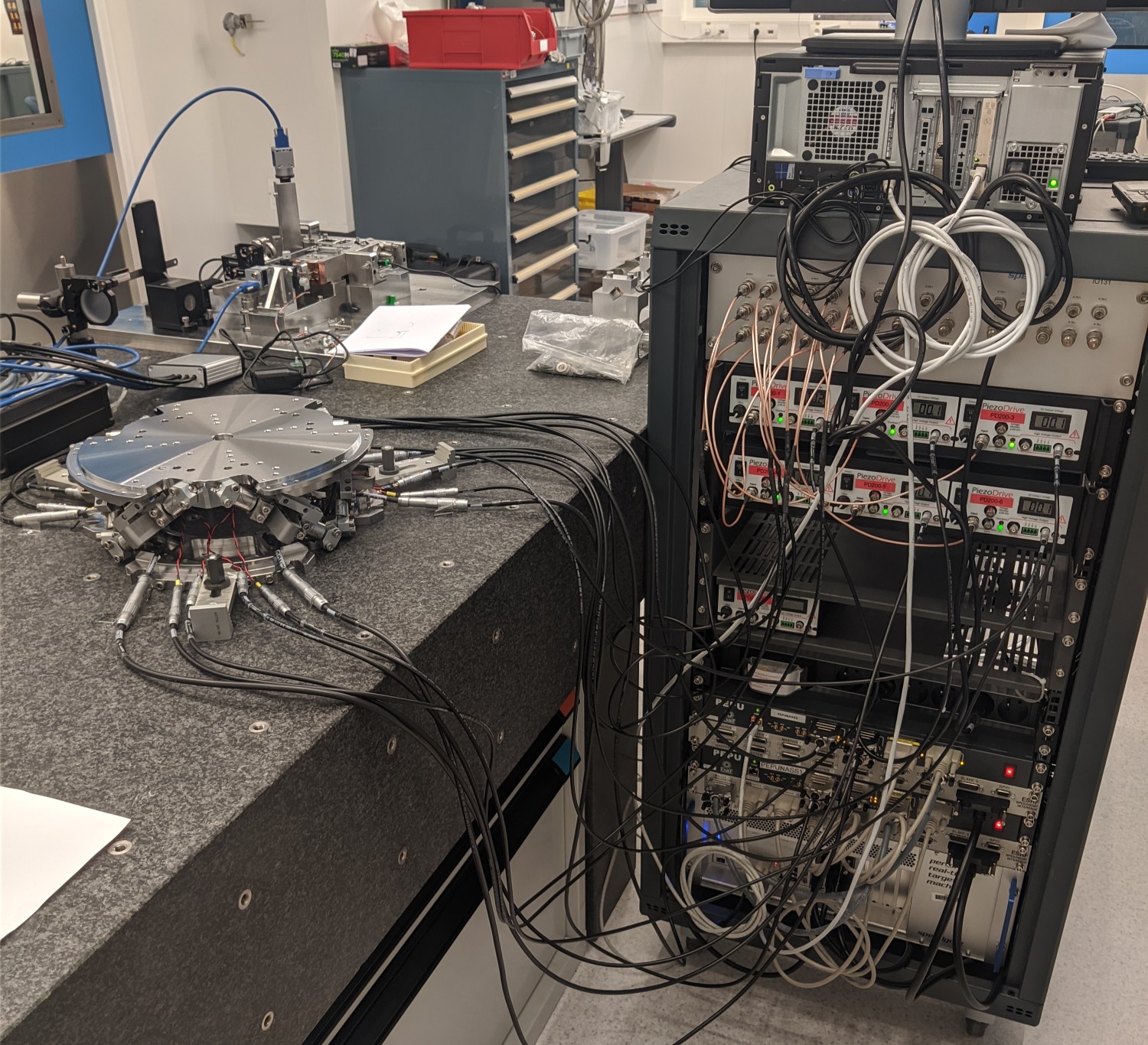
In this document, the dynamics of the nano-hexapod shown in Figure fig:picture_bench_granite_nano_hexapod is identified.
Here are the documentation of the equipment used for this test bench:
\definecolor{instrumentation}{rgb}{0, 0.447, 0.741}
\definecolor{mechanics}{rgb}{0.8500, 0.325, 0.098}

\begin{tikzpicture}
  % Blocs
  \node[block={4.0cm}{3.0cm}, fill=mechanics!20!white] (nano_hexapod) {Mechanics};
  \coordinate[] (inputF)  at (nano_hexapod.west);
  \coordinate[] (outputL) at ($(nano_hexapod.south east)!0.8!(nano_hexapod.north east)$);
  \coordinate[] (outputF) at ($(nano_hexapod.south east)!0.2!(nano_hexapod.north east)$);

  \node[block, left= 0.8 of inputF,  fill=instrumentation!20!white, align=center] (F_stack) {\tiny Actuator \\ \tiny stacks};
  \node[block, left= 0.8 of F_stack, fill=instrumentation!20!white] (PD200)   {PD200};
  \node[DAC,   left= 0.8 of PD200,   fill=instrumentation!20!white] (F_DAC)   {DAC};
  \node[block, right=0.8 of outputF, fill=instrumentation!20!white, align=center] (Fm_stack){\tiny Sensor \\ \tiny stack};
  \node[ADC,   right=0.8 of Fm_stack,fill=instrumentation!20!white] (Fm_ADC)  {ADC};
  \node[block, right=0.8 of outputL, fill=instrumentation!20!white] (encoder) {\tiny Encoder};

  % Connections and labels
  \draw[->] ($(F_DAC.west)+(-0.8,0)$) node[above right]{$\bm{u}$} node[below right]{$[V]$} -- node[sloped]{$/$} (F_DAC.west);
  \draw[->] (F_DAC.east)   -- node[midway, above]{$\tilde{\bm{u}}$}node[midway, below]{$[V]$} (PD200.west);
  \draw[->] (PD200.east)   -- node[midway, above]{$\bm{u}_a$}node[midway, below]{$[V]$} (F_stack.west);
  \draw[->] (F_stack.east) -- (inputF) node[above left]{$\bm{\tau}$}node[below left]{$[N]$};

  \draw[->] (outputF)       -- (Fm_stack.west) node[above left]{$\bm{\epsilon}$} node[below left]{$[m]$};
  \draw[->] (Fm_stack.east) -- node[midway, above]{$\tilde{\bm{\tau}}_m$}node[midway, below]{$[V]$} (Fm_ADC.west);
  \draw[->] (Fm_ADC.east)   -- node[sloped]{$/$} ++(0.8, 0)coordinate(end) node[above left]{$\bm{\tau}_m$}node[below left]{$[V]$};

  \draw[->] (outputL)      -- (encoder.west) node[above left]{$d\bm{\mathcal{L}}$} node[below left]{$[m]$};
  \draw[->] (encoder.east) -- node[sloped]{$/$} (encoder-|end) node[above left]{$d\bm{\mathcal{L}}_m$}node[below left]{$[m]$};

  % Nano-Hexapod
  \begin{scope}[on background layer]
    \node[fit={(F_stack.west|-nano_hexapod.south) (Fm_stack.east|-nano_hexapod.north)}, fill=black!20!white, draw, inner sep=2pt] (system) {};
    \node[above] at (system.north) {Nano-Hexapod};
  \end{scope}
\end{tikzpicture}| Unit | Matlab | Vector | Elements | |
|---|---|---|---|---|
| Control Input (wanted DAC voltage) | [V] |
u |
$\bm{u}$ | $u_i$ |
| DAC Output Voltage | [V] |
u |
$\tilde{\bm{u}}$ | $\tilde{u}_i$ |
| PD200 Output Voltage | [V] |
ua |
$\bm{u}_a$ | $u_{a,i}$ |
| Actuator applied force | [N] |
tau |
$\bm{\tau}$ | $\tau_i$ |
| Strut motion | [m] |
dL |
$d\bm{\mathcal{L}}$ | $d\mathcal{L}_i$ |
| Encoder measured displacement | [m] |
dLm |
$d\bm{\mathcal{L}}_m$ | $d\mathcal{L}_{m,i}$ |
| Force Sensor strain | [m] |
epsilon |
$\bm{\epsilon}$ | $\epsilon_i$ |
| Force Sensor Generated Voltage | [V] |
taum |
$\tilde{\bm{\tau}}_m$ | $\tilde{\tau}_{m,i}$ |
| Measured Generated Voltage | [V] |
taum |
$\bm{\tau}_m$ | $\tau_{m,i}$ |
| Motion of the top platform | [m,rad] |
dX |
$d\bm{\mathcal{X}}$ | $d\mathcal{X}_i$ |
| Metrology measured displacement | [m,rad] |
dXm |
$d\bm{\mathcal{X}}_m$ | $d\mathcal{X}_{m,i}$ |
Encoders fixed to the Struts
Introduction
In this section, the encoders are fixed to the struts.
Identification of the dynamics
Load Data
%% Load Identification Data
meas_data_lf = {};

for i = 1:6
    meas_data_lf(i) = {load(sprintf('mat/frf_data_exc_strut_%i_noise_lf.mat', i), 't', 'Va', 'Vs', 'de')};
    meas_data_hf(i) = {load(sprintf('mat/frf_data_exc_strut_%i_noise_hf.mat', i), 't', 'Va', 'Vs', 'de')};
end
Spectral Analysis - Setup
%% Setup useful variables
% Sampling Time [s]
Ts = (meas_data_lf{1}.t(end) - (meas_data_lf{1}.t(1)))/(length(meas_data_lf{1}.t)-1);

% Sampling Frequency [Hz]
Fs = 1/Ts;

% Hannning Windows
win = hanning(ceil(1*Fs));

% And we get the frequency vector
[~, f] = tfestimate(meas_data_lf{1}.Va, meas_data_lf{1}.de, win, [], [], 1/Ts);

i_lf = f < 250; % Points for low frequency excitation
i_hf = f > 250; % Points for high frequency excitation
DVF Plant
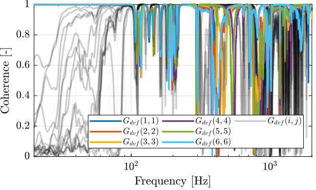
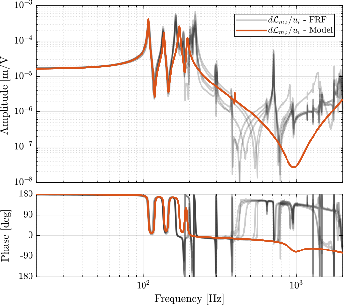
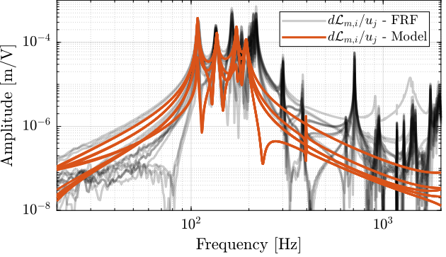
First, let's compute the coherence from the excitation voltage and the displacement as measured by the encoders (Figure fig:enc_struts_dvf_coh).
%% Coherence
coh_dvf_lf = zeros(length(f), 6, 6);
coh_dvf_hf = zeros(length(f), 6, 6);

for i = 1:6
    coh_dvf_lf(:, :, i) = mscohere(meas_data_lf{i}.Va, meas_data_lf{i}.de, win, [], [], 1/Ts);
    coh_dvf_hf(:, :, i) = mscohere(meas_data_hf{i}.Va, meas_data_hf{i}.de, win, [], [], 1/Ts);
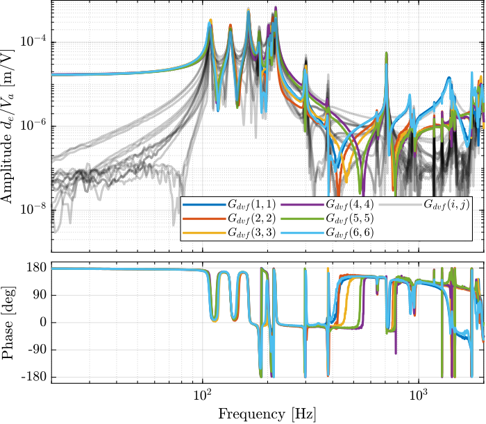
endThen the 6x6 transfer function matrix is estimated (Figure fig:enc_struts_dvf_frf).
%% DVF Plant (transfer function from u to dLm)
G_dvf_lf = zeros(length(f), 6, 6);
G_dvf_hf = zeros(length(f), 6, 6);

for i = 1:6
    G_dvf_lf(:, :, i) = tfestimate(meas_data_lf{i}.Va, meas_data_lf{i}.de, win, [], [], 1/Ts);
    G_dvf_hf(:, :, i) = tfestimate(meas_data_hf{i}.Va, meas_data_hf{i}.de, win, [], [], 1/Ts);
endIFF Plant
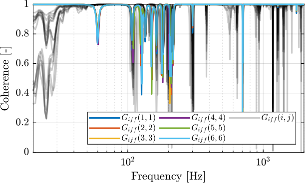
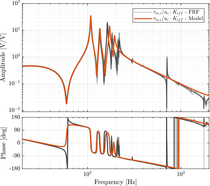
First, let's compute the coherence from the excitation voltage and the displacement as measured by the encoders (Figure fig:enc_struts_iff_coh).
%% Coherence for the IFF plant
coh_iff_lf = zeros(length(f), 6, 6);
coh_iff_hf = zeros(length(f), 6, 6);

for i = 1:6
    coh_iff_lf(:, :, i) = mscohere(meas_data_lf{i}.Va, meas_data_lf{i}.Vs, win, [], [], 1/Ts);
    coh_iff_hf(:, :, i) = mscohere(meas_data_hf{i}.Va, meas_data_hf{i}.Vs, win, [], [], 1/Ts);
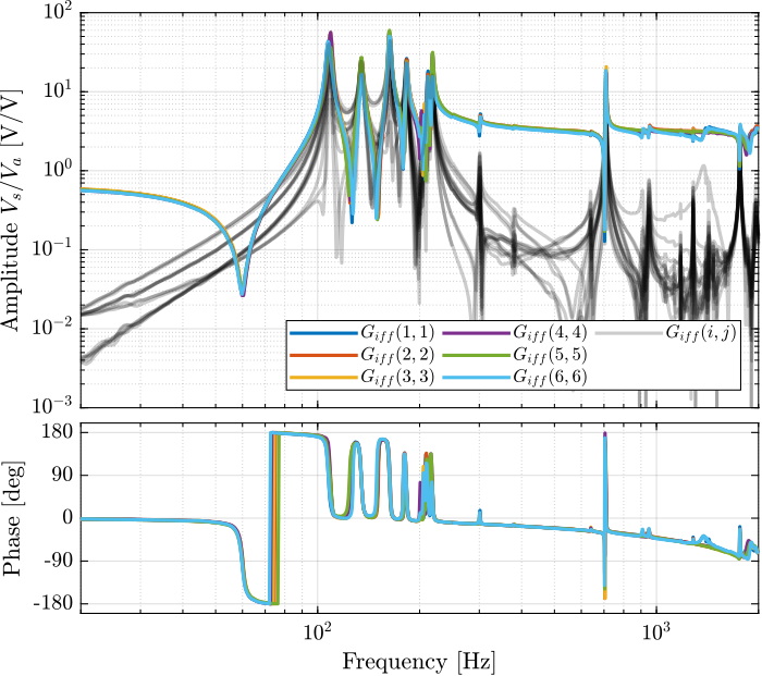
endThen the 6x6 transfer function matrix is estimated (Figure fig:enc_struts_iff_frf).
%% IFF Plant
G_iff_lf = zeros(length(f), 6, 6);
G_iff_hf = zeros(length(f), 6, 6);

for i = 1:6
    G_iff_lf(:, :, i) = tfestimate(meas_data_lf{i}.Va, meas_data_lf{i}.Vs, win, [], [], 1/Ts);
    G_iff_hf(:, :, i) = tfestimate(meas_data_hf{i}.Va, meas_data_hf{i}.Vs, win, [], [], 1/Ts);
endComparison with the Simscape Model
Introduction ignore
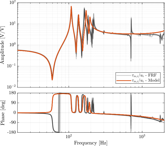
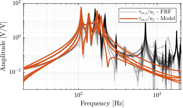
In this section, the measured dynamics is compared with the dynamics estimated from the Simscape model.
Dynamics from Actuator to Force Sensors
%% Initialize Nano-Hexapod
n_hexapod = initializeNanoHexapodFinal('flex_bot_type', '4dof', ...
                                       'flex_top_type', '4dof', ...
                                       'motion_sensor_type', 'struts', ...
                                       'actuator_type', '2dof');
%% Identify the IFF Plant (transfer function from u to taum)
clear io; io_i = 1;
io(io_i) = linio([mdl, '/F'], 1, 'openinput'); io_i = io_i + 1; % Actuator Inputs
io(io_i) = linio([mdl, '/Fm'], 1, 'openoutput'); io_i = io_i + 1; % Force Sensors
Giff = exp(-s*Ts)*linearize(mdl, io, 0.0, options);Dynamics from Actuator to Encoder
%% Initialization of the Nano-Hexapod
n_hexapod = initializeNanoHexapodFinal('flex_bot_type', '4dof', ...
                                       'flex_top_type', '4dof', ...
                                       'motion_sensor_type', 'struts', ...
                                       'actuator_type', '2dof');
%% Identify the DVF Plant (transfer function from u to dLm)
clear io; io_i = 1;
io(io_i) = linio([mdl, '/F'], 1, 'openinput'); io_i = io_i + 1; % Actuator Inputs
io(io_i) = linio([mdl, '/D'], 1, 'openoutput'); io_i = io_i + 1; % Encoders
Gdvf = exp(-s*Ts)*linearize(mdl, io, 0.0, options);Integral Force Feedback
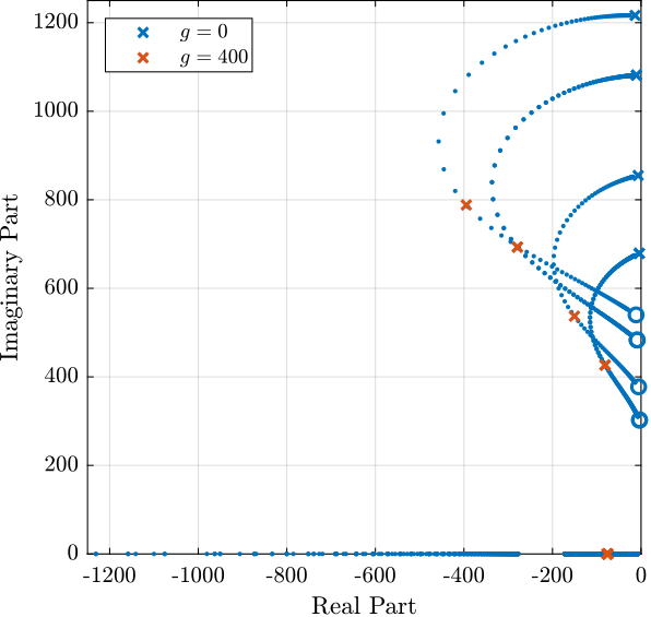
Root Locus and Decentralized Loop gain
%% IFF Controller
Kiff_g1 = (1/(s + 2*pi*40))*... % Low pass filter (provides integral action above 40Hz)
          (s/(s + 2*pi*30))*... % High pass filter to limit low frequency gain
          (1/(1 + s/2/pi/500))*... % Low pass filter to be more robust to high frequency resonances
eye(6); % Diagonal 6x6 controllerThen the "optimal" IFF controller is:
%% IFF controller with Optimal gain
Kiff = g*Kiff_g1;Multiple Gains - Simulation
%% Tested IFF gains
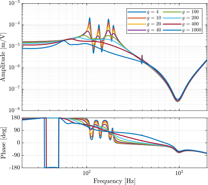
iff_gains = [4, 10, 20, 40, 100, 200, 400, 1000];
%% Initialize the Simscape model in closed loop
n_hexapod = initializeNanoHexapodFinal('flex_bot_type', '4dof', ...
'flex_top_type', '4dof', ...
'motion_sensor_type', 'struts', ...
'actuator_type', '2dof', ...
'controller_type', 'iff');%% Identify the (damped) transfer function from u to dLm for different values of the IFF gain
Gd_iff = {zeros(1, length(iff_gains))};
clear io; io_i = 1;
io(io_i) = linio([mdl, '/F'], 1, 'openinput'); io_i = io_i + 1; % Actuator Inputs
io(io_i) = linio([mdl, '/D'], 1, 'openoutput'); io_i = io_i + 1; % Strut Displacement (encoder)
for i = 1:length(iff_gains)
Kiff = iff_gains(i)*Kiff_g1*eye(6); % IFF Controller
Gd_iff(i) = {exp(-s*Ts)*linearize(mdl, io, 0.0, options)};
isstable(Gd_iff{i})
end