Flexible Joint - Test Bench
Table of Contents
1 Test Bench Description
The main characteristic of the flexible joint that we want to measure is its bending stiffness \(k_{R_x} \approx k_{R_y}\).
To do so, a test bench is used. Specifications of the test bench to precisely measure the bending stiffness are described in this section.
The basic idea is to measured the angular deflection of the flexible joint as a function of the applied torque.
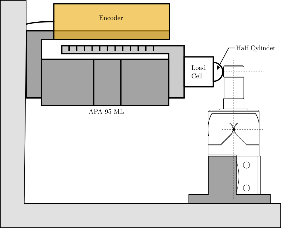
Figure 1: Schematic of the test bench to measure the bending stiffness of the flexible joints
1.1 Flexible joint Geometry
The flexible joint used for the Nano-Hexapod is shown in Figure 2. Its bending stiffness is foreseen to be \(k_{R_y}\approx 20\,\frac{Nm}{rad}\) and its stroke \(\theta_{y,\text{max}}\approx 20\,mrad\).

Figure 2: Geometry of the flexible joint
The height between the flexible point (center of the joint) and the point where external forces are applied is \(h = 20\,mm\).
Let’s define the parameters on Matlab.
kRx = 20; % Bending Stiffness [Nm/rad]
Rxmax = 20e-3; % Bending Stroke [rad]
h = 20e-3; % Height [m]
1.2 Required external applied force
The bending \(\theta_y\) of the flexible joint due to the force \(F_x\) is:
\begin{equation} \theta_y = \frac{M_y}{k_{R_y}} = \frac{F_x h}{k_{R_y}} \end{equation}Therefore, the applied force to test the full range of the flexible joint is:
\begin{equation} F_{x,\text{max}} = \frac{k_{R_y} \theta_{y,\text{max}}}{h} \end{equation}Fxmax = kRx*Rxmax/h; % Force to induce maximum stroke [N]
And we obtain:
\begin{equation} F_{max} = 20.0\, [N] \end{equation}The measurement range of the force sensor should then be higher than \(20\,N\).
1.3 Required actuator stroke and sensors range
The flexible joint is designed to allow a bending motion of \(\pm 20\,mrad\). The corresponding actuator stroke to impose such motion is:
\[ d_{x,\text{max}} = h \tan(R_{x,\text{max}}) \]
dxmax = h*tan(Rxmax);
In order to test the full range of the flexible joint, the stroke of the actuator should be higher than \(0.4\,mm\). The measurement range of the displacement sensor should also be higher than \(0.4\,mm\).
1.4 First try with the APA95ML
The APA95ML as a stroke of \(100\,\mu m\) and the encoder in parallel can easily measure the required stroke.
Suppose the full stroke of the APA can be used to bend the flexible joint (ideal case), the measured force will be:
Fxmax = kRx*100e-6/h^2; % Force at maximum stroke [N]
And the tested angular range is:
Rmax = tan(100e-6/h);