Flexible Joint - Measurement of the Bending Stiffness
Table of Contents
The goal is to design a test bench to measure the bending stiffness of a flexible joint with 1% accuracy.
1 Finite Element Model
From the Finite Element Model, the stiffnesses and strokes of the flexible joint have been computed.
ka = 94e6; % Axial Stiffness [N/m]
ks = 13e6; % Shear Stiffness [N/m]
kb = 5;    % Bending Stiffness [Nm/rad]
kt = 260;  % Torsional Stiffness [Nm/rad]
Fa = 469;    % Axial Force before yield [N]
Fs = 242;    % Shear Force before yield [N]
Fb = 0.118;  % Bending Force before yield [Nm]
Ft = 1.508; % Torsional Force before yield [Nm]
Xa = Fa/ka; % Axial Stroke before yield [m]
Xs = Fs/ks; % Shear Stroke before yield [m]
Xb = Fb/kb; % Bending Stroke before yield [rad]
Xt = Ft/kt; % Torsional Stroke before yield [rad]
| Stiffness [N/um] | Max Force [N] | Stroke [um] | |
|---|---|---|---|
| Axial | 94 | 469 | 5 |
| Shear | 13 | 242 | 19 |
| Stiffness [Nm/rad] | Max Torque [Nmm] | Stroke [mrad] | |
|---|---|---|---|
| Bending | 5 | 118 | 24 |
| Torsional | 260 | 1508 | 6 |
2 Setup
3 Effect of Bending
The torque applied is:
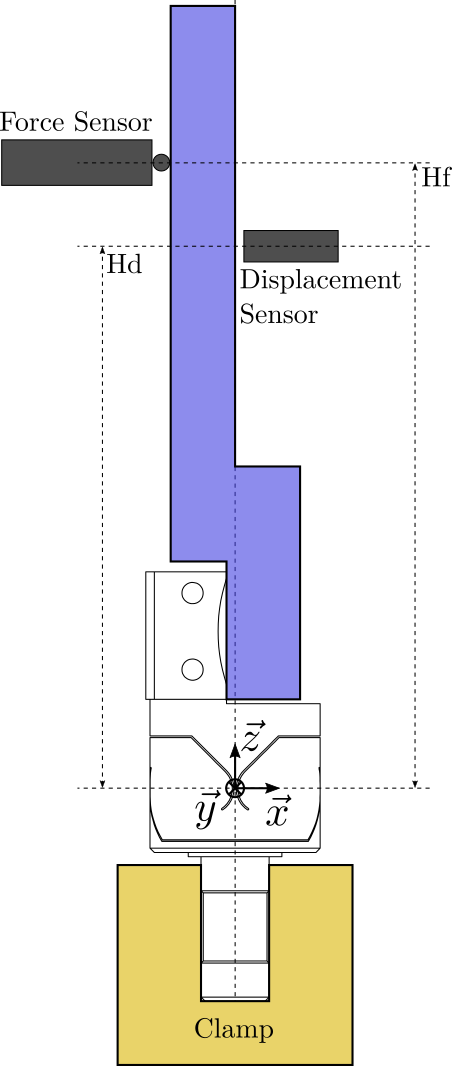
\begin{equation} M_b = F \cdot H_F \end{equation}The flexible joint is experiencing a rotation \(R_b\) due to the torque \(M_b\):
\begin{equation} R_b = \frac{M_b}{k_b} = \frac{F \cdot H_F}{k_b} \end{equation}This rotation is then measured by the displacement sensor. The measured displacement is:
\begin{equation} D_b = H_D \tan(R_b) = H_D \tan\left( \frac{F \cdot H_F}{k_b} \right) \label{eq:bending_meaured_disp} \end{equation}4 Computation of the bending stiffness
From equation \eqref{eq:bending_meaured_disp}, we can compute the bending stiffness:
\begin{equation} k_b = \frac{\tan^{-1}\left( \frac{D_b}{H_D} \right)}{F \cdot H_F} \end{equation}And therefore, to precisely measure \(k_b\), we need to:
- precisely measure the motion \(D_b\)
- precisely measure the applied force \(F\)
- precisely know the height from the flexible joint’s center to the measurement point \(H_D\)
- precisely know the height from the flexible joint’s center to the force application point \(H_F\)
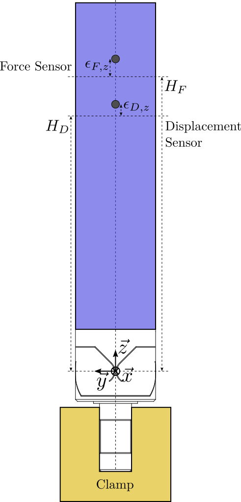
If there are estimation errors for \(H_D\) or \(H_F\) as shown in Figure 2, this will induce an error for the estimation of the stiffness.
For 1% accuracy estimation of \(k_b\), we can write the following approximate requirements:
| Accuracy | |
|---|---|
| Force Measurement | 1% |
| Displacement Measurement | 1% |
| \(H_D\) | 1% |
| \(H_F\) | 1% |

Figure 2: Error in the estimation of the height of the force sensor and displacement sensor
5 Effect of Shear
The effect of Shear on the measured displacement is simply:
\begin{equation} D_s = \frac{F}{k_s} \end{equation}We would like to have this displacement much smaller than the displacement induced by the bending effects:
\begin{equation} D_b \gg D_s \end{equation}Which is equivalent as to have:
\begin{equation} H_D \tan\left( \frac{F \cdot H_F}{k_b} \right) \gg \frac{F}{k_s} \end{equation}Here to simplify, we suppose \(FH_F/k_b \ll 1\) (which is the case in practice), and we suppose \(H_D = H_F = H\).
The obtained condition is then:
\begin{equation} H \gg \frac{k_b}{k_s} \end{equation}| 10% error | 1% error | 0.1% error | |
|---|---|---|---|
| \(H\,[mm]\) | 6 | 62 | 620 |
In order to limit the effect of shear of less than 1%, the height from the joint’s center to the force application point and to the measurement point should be larger than 62mm.
H = 62e-3; % [m]
6 Effect of Torsion
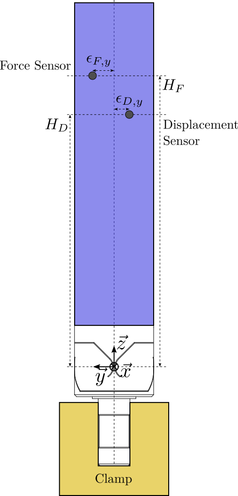
If the application force is not aligned with the vertical axis of the flexible joint, this will induce a torsion motion that will induce a measurement error (Figure 3).

Figure 3: Horizontal position error of the force sensor and displacement sensor
Let’s note the offset of the force sensor \(\epsilon_{F,y}\) and the offset of the measurement point \(\epsilon_{D,y}\). The vertical torque (torsion) will be equal to:
\begin{equation} M_t = F \cdot \epsilon_{F,y} \end{equation}And the induced torsion:
\begin{equation} R_t = \frac{M_t}{k_t} = \frac{F \cdot \epsilon_{F,y}}{k_t} \end{equation}The effect on the measured displacement is:
\begin{equation} D_t = \epsilon_{D,y} \tan \left( R_t \right) = \epsilon_{D,y} \tan\left( \frac{F \cdot \epsilon_{F,y}}{k_t} \right) \end{equation}And we would like to have:
\begin{equation} D_b \gg D_t \end{equation}Which is equivalent as to have:
\begin{equation} H_D \tan\left( \frac{F \cdot H_F}{k_b} \right) \gg \epsilon_{D,y} \tan\left( \frac{F \cdot \epsilon_{F,y}}{k_t} \right) \end{equation}Supposing \(H_F = H_D = H\) and \(\epsilon_{F,y} = \epsilon_{D,y} = \epsilon_{y}\), the condition becomes:
\begin{equation} \epsilon_{y} \ll H \sqrt{\frac{k_t}{k_b}} \end{equation}| 10% error | 1% error | 0.1% error | |
|---|---|---|---|
| \(\epsilon_y\,[mm]\) | 44.7 | 4.5 | 0.4 |
For 1% error, the lateral positioning errors \(\epsilon_y\) for both the force sensor and the displacement sensor should be less than 4.5mm.
7 Full stroke measured displacement and applied force as a function of \(H\)
Applying a force with a large height \(H\) means the induced rotation (for constant force) will be larger. This also means that the measured displacement \(D_b\) will also be larger.
Note that we here suppose the force axis is co-linear with the measurement axis (\(H_F = H_D = H\)).
Let’s compute:
- \(D_b\) as a function of \(H\) \[ D_b \approx H \tan (R_b) \]
- the applied force \(F_{\text{max}}\) to induce the maximum rotation as a function of \(H\) \[ F_{\text{max}} \approx \frac{X_b \cdot k_b}{H} \]

Figure 4: Applied force \(F_{\text{max}}\) and measured displacement \(D_b\) as a function of \(H\)
With an offset of 62mm, we obtained values shown in Table 3.
| \(D_b\,[mm]\) | \(F_m\,[N]\) |
|---|---|
| 1.5 | 1.9 |
8 Negligible bending of the supporting bar
This should be confirmed with FEM.
9 Conclusion
| Range | Accuracy | |
|---|---|---|
| Force Measurement | 2 N | 1% = 0.02 N |
| Displacement Measurement | 1.5 mm | 1% = 15 um |
| Value | Precision | Comment | |
|---|---|---|---|
| \(H_D\) | 62mm | For negligible Shear | |
| \(H_F\) | 62mm | Same | |
| \(\epsilon_y\) | 0 | 4.5mm | For negligible Torsion |
| \(\epsilon_z\) | 0 | 1% = 0.6mm | For torque estimation precision |
Load cells:
- https://www.te.com/usa-en/product-CAT-FLS0020.html?q=&n=510872&d=681051%20564247&type=products&samples=N&inStoreWithoutPL=false&instock=N#mdp-tabs-content
- https://www.digikey.com/en/products/detail/honeywell-sensing-and-productivity-solutions/FSS005WNSB/6056404
Displacement sensors:
