Amplifier Piezoelectric Actuator APA300ML - Test Bench
Table of Contents
The goal of this test bench is to extract all the important parameters of the Amplified Piezoelectric Actuator APA300ML.
This include:
- Stroke
- Stiffness
- Hysteresis
- Gain from the applied voltage \(V_a\) to the generated Force \(F_a\)
- Gain from the sensor stack strain \(\delta L\) to the generated voltage \(V_s\)
1 Model of an Amplified Piezoelectric Actuator and Sensor
Consider a schematic of the Amplified Piezoelectric Actuator in Figure 1.
A voltage \(V_a\) applied to the actuator stacks will induce an actuator force \(F_a\):
\begin{equation} F_a = g_a \cdot V_a \end{equation}A change of length \(dl\) of the sensor stack will induce a voltage \(V_s\):
\begin{equation} V_s = g_s \cdot dl \end{equation}We wish here to experimental measure \(g_a\) and \(g_s\).

Figure 1: Amplified Piezoelectric Actuator Schematic
2 Test-Bench Description
Here are the documentation of the equipment used for this test bench:
- Voltage Amplifier: PD200
- Amplified Piezoelectric Actuator: APA300ML
- DAC/ADC: Speedgoat IO313
- Encoder: Renishaw Vionic and used Ruler
- Interferometer: Attocube IDS3010
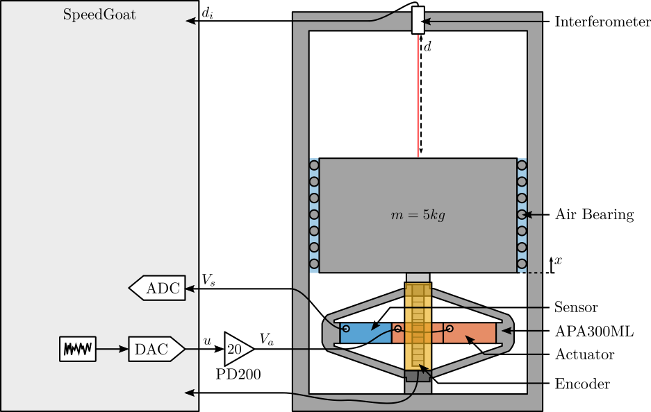
Figure 2: Schematic of the Test Bench
3 Measurement Procedure
3.1 Stroke Measurement
Using the PD200 amplifier, output a voltage: \[ V_a = 65 + 85 \sin(2\pi \cdot t) \] To have a quasi-static excitation between -80 and 150V.
As the gain of the PD200 amplifier is 20, the DAC output voltage should be: \[ V_{dac}(t) = 3.25 + 4.25\sin(2\pi \cdot t) \]
Verify that the voltage offset is zero!
Measure the output vertical displacement \(d\) using the interferometer.
Then, plot \(d\) as a function of \(V_a\), and perform a linear regression. Conclude on the obtained stroke.
3.2 Stiffness Measurement
Add some (known) weight \(\delta m g\) on the suspended mass and measure the deflection \(\delta d\). This can be tested when the piezoelectric stacks are open-circuit.
As the stiffness will be around \(k \approx 10^6 N/m\), an added mass of \(m \approx 100g\) will induce a static deflection of \(\approx 1\mu m\) which should be large enough for a precise measurement using the interferometer.
Then the obtained stiffness is:
\begin{equation} k = \frac{\delta m g}{\delta d} \end{equation}3.3 Hysteresis measurement
Supply a quasi static sinusoidal excitation \(V_a\) at different voltages.
The offset should be 65V, and the sin amplitude can range from 1V up to 85V.
For each excitation amplitude, the vertical displacement \(d\) of the mass is measured.
Then, \(d\) is plotted as a function of \(V_a\) for all the amplitudes.
3.4 Piezoelectric Actuator Constant
Using the measurement test-bench, it is rather easy the determine the static gain between the applied voltage \(V_a\) to the induced displacement \(d\). Use a quasi static (1Hz) excitation signal \(V_a\) on the piezoelectric stack and measure the vertical displacement \(d\). Perform a linear regression to obtain:
\begin{equation} d = g_{d/V_a} \cdot V_a \end{equation}Using the Simscape model of the APA, it is possible to determine the static gain between the actuator force \(F_a\) to the induced displacement \(d\):
\begin{equation} d = g_{d/F_a} \cdot F_a \end{equation}From the two gains, it is then easy to determine \(g_a\):
\begin{equation} g_a = \frac{F_a}{V_a} = \frac{F_a}{d} \cdot \frac{d}{V_a} = \frac{g_{d/V_a}}{g_{d/F_a}} \end{equation}3.5 Piezoelectric Sensor Constant
From a quasi static (1Hz) excitation of the piezoelectric stack, measure the gain from \(V_a\) to \(V_s\):
\begin{equation} V_s = g_{V_s/V_a} V_a \end{equation}Using the simscape model, compute the static gain from the actuator force \(F_a\) to the strain of the sensor stack \(dl\):
\begin{equation} dl = g_{dl/F_a} F_a \end{equation}Then, the static gain from the sensor stack strain \(dl\) to the general voltage \(V_s\) is:
\begin{equation} g_s = \frac{V_s}{dl} = \frac{V_s}{V_a} \cdot \frac{V_a}{F_a} \cdot \frac{F_a}{dl} = \frac{g_{V_s/V_a}}{g_a \cdot g_{dl/F_a}} \end{equation}Alternatively, we could impose an external force to add strain in the APA that should be equally present in all the 3 stacks and equal to 1/5 of the vertical strain. This external force can be some weight added, or a piezo in parallel.
3.6 Capacitance Measurement
Measure the capacitance of the 3 stacks individually using a precise multi-meter.