Measurement of Loudspeaker
Table of Contents
This report is also available as a pdf.
Because of the lack of a large anechoic room or a near field scanner system (e.g. the Klippel NFS), the low frequency and high frequency response of the speaker have to be measured separately.
- Section 1: the tools used for the measurements are listed
- Section 2: the high frequency behavior of the speaker is measured with a semi-anechoic measurement performed outdoors
- Section 3: the low frequency behavior of the speaker is measured using the “ground plane technique”
- Section 4: the response of the speaker in a typical room is estimated from the two above measurements and compare with in-room measurements
1 Equipment
2 Semi-Anechoic Outdoor measurement
The frequency resolution is limited by the time difference between the direct sound and the first reflection.
If we note \(\tau\) this time difference, the frequency resolution \(\delta f\) is:
\begin{equation} \delta f = \frac{1}{\tau} \end{equation}with \(\delta f\) in hertz and \(\tau\) in seconds.
A schematic of the setup is shown in Figure 1.
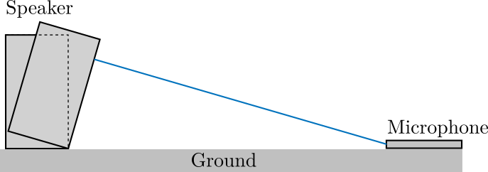
Figure 1: Schematic of the setup
We usually want to measure the speaker with a resonable distance. Let’s take \(L = 2\,m\).
L = 2; % Distance speaker/microphone [m]
v = 340; % Speed of sound [m/s]
We can then compute the time delay \(\tau\) between the direct sound and reflected sound as a function of the height \(H\). Similarly, we can compute the frequency resolution \(\delta f\) as a function of \(H\). Both are shown in Figure 2.
H = [0:0.01:4]; % [m]

D = 2*sqrt(H.^2 + L^2/4); % [m]
tau = (D - L)/v; % [s]
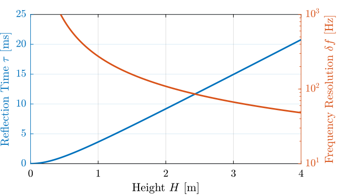
Figure 2: Time delay \(\tau\) between the direct sound and (first) reflected sound as a function of the height \(H\). The resulting frequency resolution \(\delta f\) is also shown.
It is shown than even for high heights (\(H = 3\,m\)), the frequency resolution will be quite poor for low frequency characterisation of the speaker (\(\delta f \approx 70\,Hz\)). However, it is much sufficient for high frequency characterisation of the speaker (say above 500Hz).
The speaker can then be tilted horizontally and vertically as shown in Figure 3 and 4.
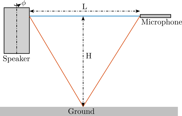
Figure 3: Tilting the speaker around a vertical axis
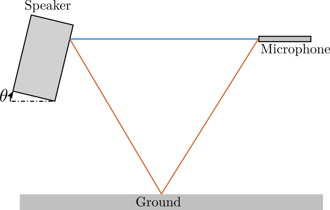
Figure 4: Tilting the speaker around a horizontal axis
3 Ground Plane Technique
The idea here is to put both the microphone and the speaker on the ground.
The ground must be relatively stiff.
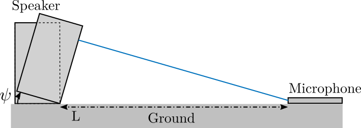
Figure 5: Schematic of the measurement setup
It is then possible to use very large gate windows in order to identify the low frequency behavior of the speaker.
It is here not useful to perform any off-axis measurements as at the frequencies, the speaker is perfectly omnidirectionnal.