Evaluating the Plant Uncertainty in various experimental conditions
Table of Contents
The goal of this document is to study how the dynamics of the system is changing with the experimental conditions.
These experimental conditions are:
- Section 1: Sample mass (from 1Kg to 50Kg)
- Section 2: Sample dynamics (mostly main resonance frequency)
- Section 3: The spindle angle
- Section 4: The spindle rotation speed (from 1rpm to 60rpm)
- Section 5: The tilt angle (from -3 to 3 degrees)
- Section 6: Pose of the micro-hexapod
We are interested in the dynamics from the nano-hexapod actuators to:
- the sensors included in the nano-hexapod (force sensor, relative motion sensor)
- the measured position of the sample with respect to the granite
The variability of the dynamics is studied for two nano-hexapod concepts:
- a soft nano-hexapod
- a stiff nano-hexapod
The conclusions are drawn in Section 7
1 Variation of the Sample Mass
We here study the change of dynamics due to the sample mass. To see only the effect of the sample mass, we keep the same resonance frequency of the sample, and we set it to 10kHz so it is above the dynamics of interest.
We initialize all the stages with the default parameters. We identify the dynamics for the following sample masses, both with a soft and stiff nano-hexapod.
masses = [1, 10, 50]; % [kg]
The following transfer functions are shown:
- Figure 1: From actuator forces to force sensors in each nano-hexapod’s leg
- Figure 2: From actuator forces to relative displacement of each nano-hexapod’s leg
- Figure 3 (resp. 4): From forces applied in the task space by the nano-hexapod to displacement of the sample in the X direction (resp. in the Z direction)
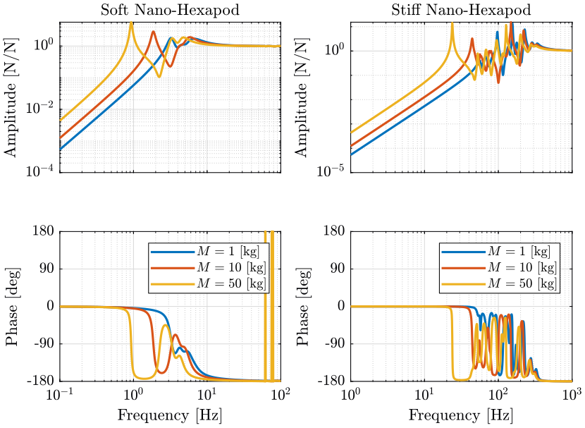
Figure 1: Variability of the dynamics from actuator force to force sensor with the Sample Mass (png, pdf)

Figure 2: Variability of the dynamics from actuator force to relative motion sensor with the Sample Mass (png, pdf)

Figure 3: Variability of the dynamics from Forces applied in task space (X direction) to the displacement of the sample in the X direction (png, pdf)

Figure 4: Variability of the dynamics from vertical forces applied in the task space to the displacement of the sample in the vertical direction (png, pdf)
Let’s note \(\omega_0\) the first resonance which corresponds to the resonance of the payload+nano-hexapod top platform resonating on top of the nano-hexapod base.
An increase of the payload mass decreases \(\omega_0\). This is more easily seem with the soft nano-hexapod as the resonance \(\omega_0\) is separated from the resonances of the micro-station.
- For the soft nano-hexapod, the main effect is the change of \(\omega_0\).
- For the stiff nano-hexapod, it also affects the others resonances corresponding to the resonances of the micro-station
| \(\frac{\tau_{mi}}{\tau_m}\) | \(\frac{d\mathcal{L}_i}{\tau_i}\) | \(\frac{\mathcal{X}_i}{\mathcal{F}_i}\) | |
|---|---|---|---|
| Soft Nano-Hexapod | Changes the low frequency gain | Changes the high frequency gain | Changes \(\omega_0\) and high frequency gain |
| Stiff Nano-Hexapod | Changes the location of the modes and low frequency gain | Changes the location of the modes and high frequency gain | Changes the dynamics above \(\omega_0\) |
2 Variation of the Sample Resonance Frequency
We initialize all the stages with the default parameters. We identify the dynamics for the following sample resonance frequency.
mass_w = [50, 100, 500]; % [Hz]
mass = 10; % [Kg]
The following transfer functions are shown:
- Figure 5: From actuator forces to force sensors in each nano-hexapod’s leg
- Figure 6: From actuator forces to relative displacement of each nano-hexapod’s leg
- Figure 7: From forces applied in the task space by the nano-hexapod to displacement of the sample in the X direction
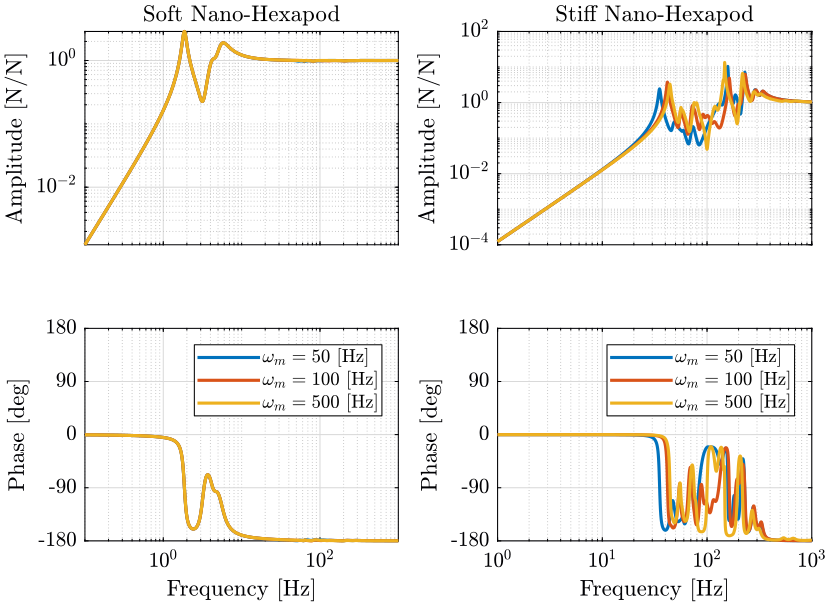
Figure 5: Variability of the dynamics from actuator force to force sensor with the Sample Mass (png, pdf)
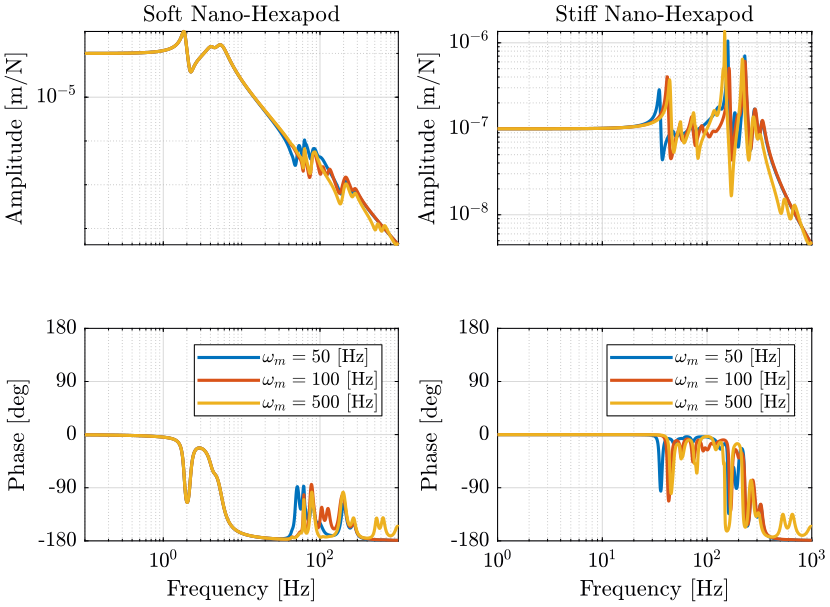
Figure 6: Variability of the dynamics from actuator force to relative motion sensor with the Sample Mass (png, pdf)
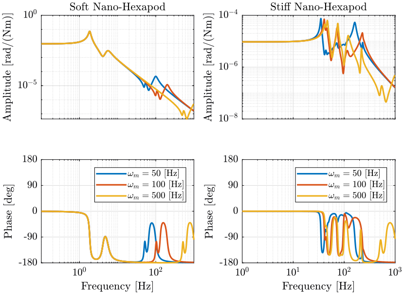
Figure 7: Variability of the dynamics from a torque applied on the sample by the nano-hexapod in the X direction to the rotation of the sample around the X axis (png, pdf)
Let’s note \(\omega_m\) the frequency of the resonance of the Payload.
| \(\frac{\tau_{mi}}{\tau_m}\) | \(\frac{d\mathcal{L}_i}{\tau_i}\) | \(\frac{\mathcal{X}_i}{\mathcal{F}_i}\) | |
|---|---|---|---|
| Soft Nano-Hexapod | No visible effect | Small effect around \(\omega_m\) | Two c.c. zeros at \(\omega_m\) followed by two c.c. poles |
| Stiff Nano-Hexapod | Slightly change the dynamics | Slightly change the dynamics | Greatly affect the dynamics above the first resonance |
3 Variation of the Spindle Angle
3.1 Identification
We identify the dynamics for the following Tilt stage angles.
initializeSample('mass', 50);
Rz_amplitudes = [0, pi/4, pi/2, pi]; % [rad]
The following transfer functions are shown:
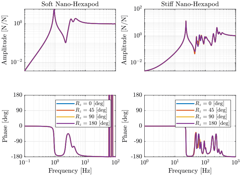
The Spindle angle has no visible effect for the soft nano-hexapod.
It has little effect on the dynamics when a stiff nano-hexapod is used. This is seem between 50Hz and 100Hz. This is probably due to the fact that the micro-station compliance is not uniform in the X and Y directions.
4 Variation of the Spindle Rotation Speed
4.1 Initialization of gravity compensation forces
We initialize all the stages such that their joints are blocked and we record the total forces/torques applied in each of these joints. We set a payload mass of 10Kg.
initializeSample('type', 'init', 'mass', 10);
nano_hexapod = initializeNanoHexapod( 'type', 'init');
Finally, we simulate the system and same the forces/torques applied in each joint.
4.2 Identification
We initialize the stages with forces/torques compensating the gravity forces. We identify the dynamics for the following Spindle rotation periods.
Rz_periods = [60, 6, 2, 1]; % [s]
4.3 Plots
The following transfer functions are shown:
- Figure 10: From actuator forces to force sensors in each nano-hexapod’s leg
- Figure 11: From actuator forces to relative displacement of each nano-hexapod’s leg
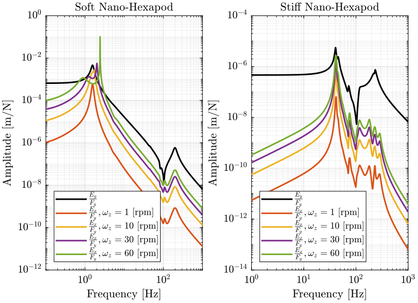
- Figure 12: From forces applied in the task space by the nano-hexapod to displacement of the sample in the X direction
- Figure 13: From forces applied in the task space in the X direction by the nano-hexapod to displacement of the sample in the Y direction (coupling)
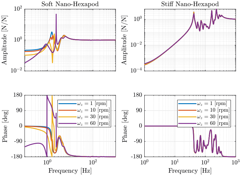
Figure 10: Variability of the dynamics from the actuator force to the force sensor with the Spindle rotation speed (png, pdf)
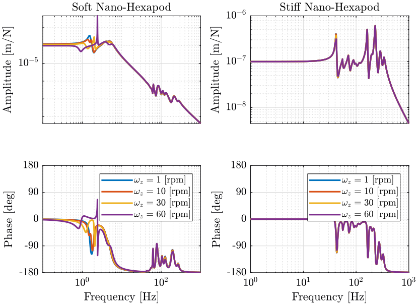
Figure 11: Variability of the dynamics from the actuator force to the relative motion sensor with the Spindle rotation speed (png, pdf)

For the stiff nano-hexapod, the rotation speed of the Spindle does not affect the (main) dynamics. It only affects the coupling due to Coriolis forces.
For the soft nano-hexapod, it greatly affects the obtained dynamics around the main resonance which corresponds to the payload vibrating on top of the nano-hexapod.
This effect is similar to the one described in rotating machinery, the c.c. poles is separated into two sets of c.c. poles, one going to decreasing frequencies while the other going to positive frequencies. This effect is due to centrifugal forces that can be modeled as negative stiffness. At some point, one of the pair of c.c. pole becomes unstable.
Also, the coupling from forces applied in the X direction to induced displacement in the Y direction becomes very high when the rotating speed is increased.
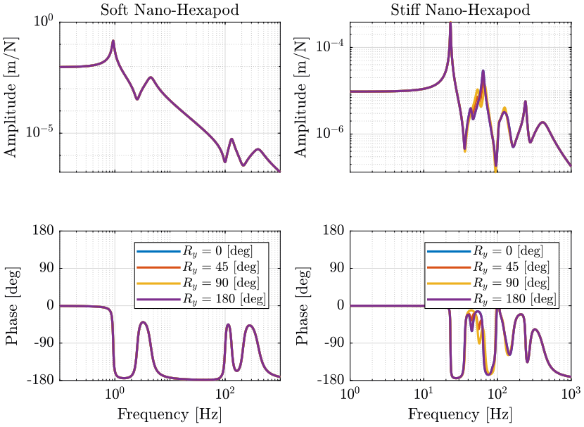
5 Variation of the Tilt Angle
We initialize all the stages with the default parameters. We identify the dynamics for the following Tilt stage angles.
initializeSample('mass', 50);
Ry_amplitudes = [-3*pi/180 0 3*pi/180]; % [rad]
The following transfer functions are shown:
- Figure 14: From actuator forces to force sensors in each nano-hexapod’s leg
- Figure 15: From forces applied in the task space by the nano-hexapod to displacement of the sample in the X direction
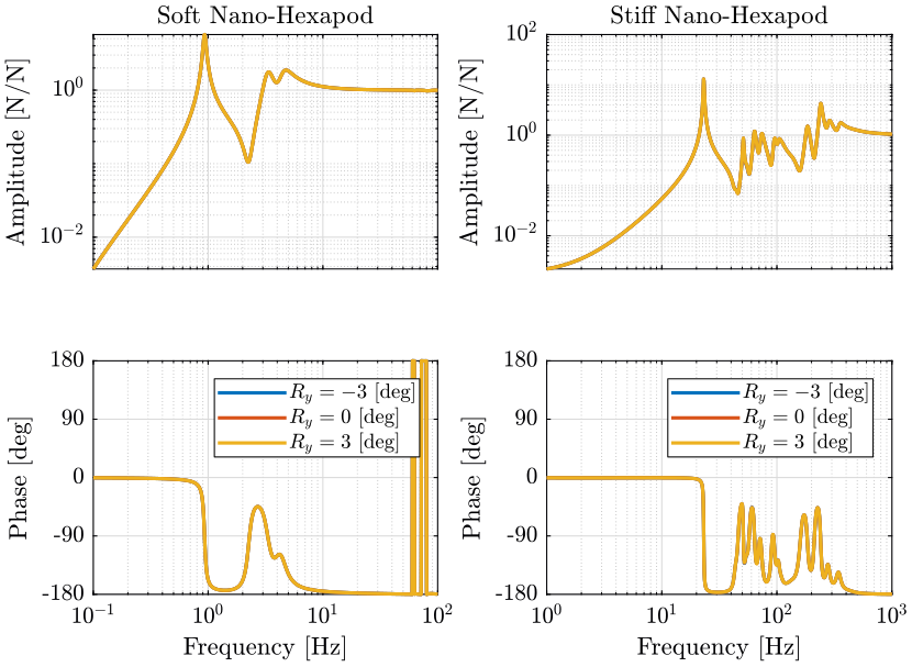
Figure 14: Variability of the dynamics from the actuator force to the force sensor with the Tilt stage Angle (png, pdf)
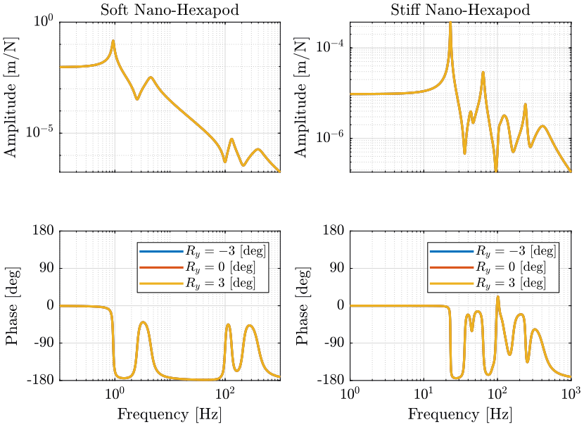
Figure 15: Variability of the dynamics from the actuator force in the task space to the displacement of the sample (png, pdf)
The tilt angle has no visible effect on the dynamics.
6 Variation of the micro-hexapod pose
We initialize all the stages with the default parameters. We identify the dynamics for the following translations of the micro-hexapod in the X direction.
Tx_amplitudes = [0, 5e-3, 10e-3]; % [m]
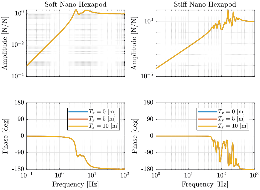
Figure 16: Variability of the dynamics from the actuator force to the force sensor with the Tilt stage Angle (png, pdf)
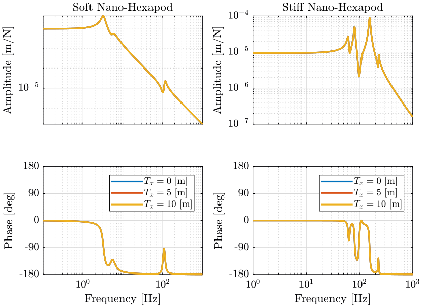
Figure 17: Variability of the dynamics from the actuator force in the task space to the displacement of the sample (png, pdf)
The pose of the micro-hexapod has negligible effect on the dynamics.
7 Conclusion
From all the experimental condition studied, the only ones that have significant effect on the dynamics are:
- the sample mass
- the resonance frequency of the sample
- the rotation speed of the spindle
| Soft | Stiff | |
|---|---|---|
| Sample Mass | Localized effect on the resonance of the sample | Effect on all the modes |
| Sample Resonance | Localized effect at the resonance of the sample | Effect on all the modes |
| Rotation Speed | Greatly influences the dynamics and coupling | No effect |