Subsystems used for the Simscape Models
Table of Contents
- 1. Simscape Configuration
- 2. Logging Configuration
- 3. Ground
- 4. Granite
- 5. Translation Stage
- 6. Tilt Stage
- 7. Spindle
- 8. Micro Hexapod
- 9. Center of gravity compensation
- 10. Mirror
- 11. Nano Hexapod
- 12. Sample
- 13. Initialize Controller
- 14. Generate Reference Signals
- 15. Initialize Disturbances
- 16. Initialize Position Errors
- 17. Z-Axis Geophone
- 18. Z-Axis Accelerometer
The full Simscape Model is represented in Figure 1.
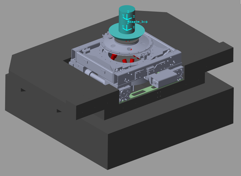
Figure 1: Screenshot of the Multi-Body Model representation
This model is divided into multiple subsystems that are independent. These subsystems are saved in separate files and imported in the main file using a block balled “subsystem reference”.
Each stage is configured (geometry, mass properties, dynamic properties …) using one function.
These functions are defined below.
1 Simscape Configuration
Function description
function [] = initializeSimscapeConfiguration(args)
Optional Parameters
arguments
  args.gravity logical {mustBeNumericOrLogical} = true
end
Structure initialization
conf_simscape = struct();
Add Type
if args.gravity
  conf_simscape.type = 1;
else
  conf_simscape.type = 2;
end
Save the Structure
save('./mat/conf_simscape.mat', 'conf_simscape');
2 Logging Configuration
Function description
function [] = initializeLoggingConfiguration(args)
Optional Parameters
arguments
  args.log      char   {mustBeMember(args.log,{'none', 'all', 'forces'})} = 'none'
  args.Ts (1,1) double {mustBeNumeric, mustBePositive} = 1e-3
end
Structure initialization
conf_log = struct();
Add Type
switch args.log
  case 'none'
    conf_log.type = 0;
  case 'all'
    conf_log.type = 1;
  case 'forces'
    conf_log.type = 2;
end
Sampling Time
conf_log.Ts = args.Ts;
Save the Structure
save('./mat/conf_log.mat', 'conf_log');
3 Ground
Simscape Model
The model of the Ground is composed of:
- A Cartesian joint that is used to simulation the ground motion
- A solid that represents the ground on which the granite is located
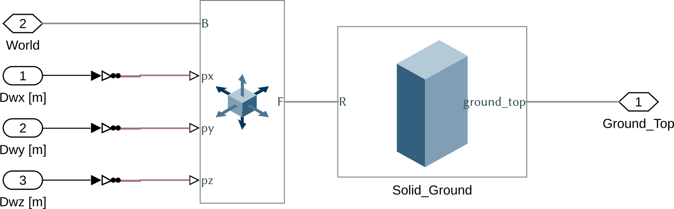
Figure 2: Simscape model for the Ground
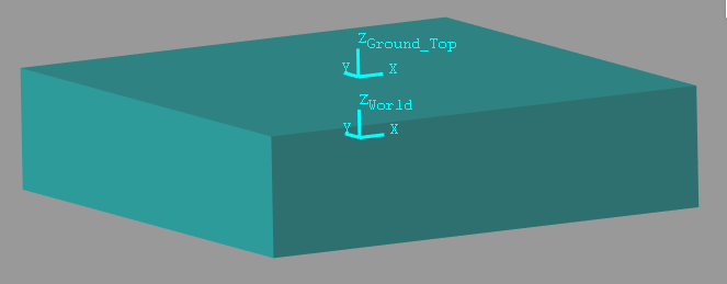
Figure 3: Simscape picture for the Ground
Function description
function [ground] = initializeGround(args)
Optional Parameters
arguments
  args.type char {mustBeMember(args.type,{'none', 'rigid'})} = 'rigid'
  args.rot_point (3,1) double {mustBeNumeric} = zeros(3,1) % Rotation point for the ground motion [m]
end
Structure initialization
First, we initialize the granite structure.
ground = struct();
Add Type
switch args.type
  case 'none'
    ground.type = 0;
  case 'rigid'
    ground.type = 1;
end
Ground Solid properties
We set the shape and density of the ground solid element.
ground.shape   = [2, 2, 0.5]; % [m]
ground.density = 2800;        % [kg/m3]
Rotation Point
ground.rot_point = args.rot_point;
Save the Structure
The ground structure is saved.
save('./mat/stages.mat', 'ground', '-append');
4 Granite
Simscape Model
The Simscape model of the granite is composed of:
- A cartesian joint such that the granite can vibrations along x, y and z axis
- A solid
The output sample_pos corresponds to the impact point of the X-ray.
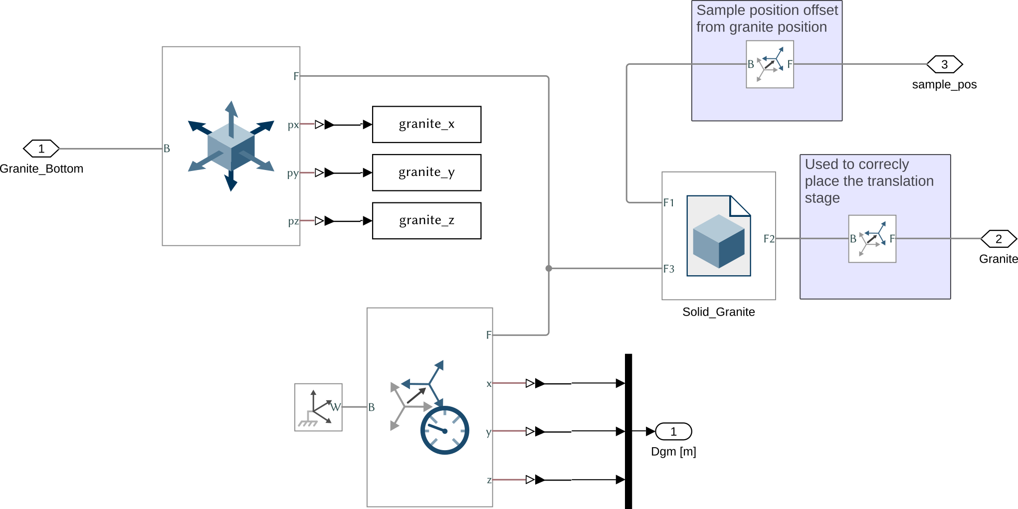
Figure 4: Simscape model for the Granite
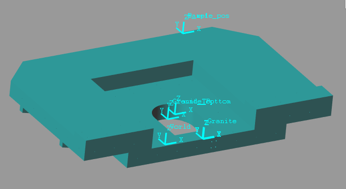
Figure 5: Simscape picture for the Granite
Function description
function [granite] = initializeGranite(args)
Optional Parameters
arguments
  args.type          char    {mustBeMember(args.type,{'rigid', 'flexible', 'none', 'modal-analysis', 'init'})} = 'flexible'
  args.Foffset       logical {mustBeNumericOrLogical} = false
  args.density (1,1) double {mustBeNumeric, mustBeNonnegative} = 2800 % Density [kg/m3]
  args.x0 (1,1) double {mustBeNumeric} = 0 % Rest position of the Joint in the X direction [m]
  args.y0 (1,1) double {mustBeNumeric} = 0 % Rest position of the Joint in the Y direction [m]
  args.z0 (1,1) double {mustBeNumeric} = 0 % Rest position of the Joint in the Z direction [m]
end
Structure initialization
First, we initialize the granite structure.
granite = struct();
Add Granite Type
switch args.type
  case 'none'
    granite.type = 0;
  case 'rigid'
    granite.type = 1;
  case 'flexible'
    granite.type = 2;
  case 'modal-analysis'
    granite.type = 3;
  case 'init'
    granite.type = 4;
end
Material and Geometry
Properties of the Material and link to the geometry of the granite.
granite.density = args.density; % [kg/m3]
granite.STEP    = './STEPS/granite/granite.STEP';
Z-offset for the initial position of the sample with respect to the granite top surface.
granite.sample_pos = 0.8; % [m]
Stiffness and Damping properties
granite.K = [4e9; 3e8; 8e8]; % [N/m]
granite.C = [4.0e5; 1.1e5; 9.0e5]; % [N/(m/s)]
Equilibrium position of the each joint.
if args.Foffset && ~strcmp(args.type, 'none') && ~strcmp(args.type, 'rigid') && ~strcmp(args.type, 'init')
  load('mat/Foffset.mat', 'Fgm');
  granite.Deq = -Fgm'./granite.K;
else
  granite.Deq = zeros(6,1);
end
Save the Structure
The granite structure is saved.
save('./mat/stages.mat', 'granite', '-append');
5 Translation Stage
Simscape Model
The Simscape model of the Translation stage consist of:
- One rigid body for the fixed part of the translation stage
- One rigid body for the moving part of the translation stage
- Four 6-DOF Joints that only have some rigidity in the X and Z directions. The rigidity in rotation comes from the fact that we use multiple joints that are located at different points
- One 6-DOF joint that represent the Actuator. It is used to impose the motion in the Y direction
- One 6-DOF joint to inject force disturbance in the X and Z directions
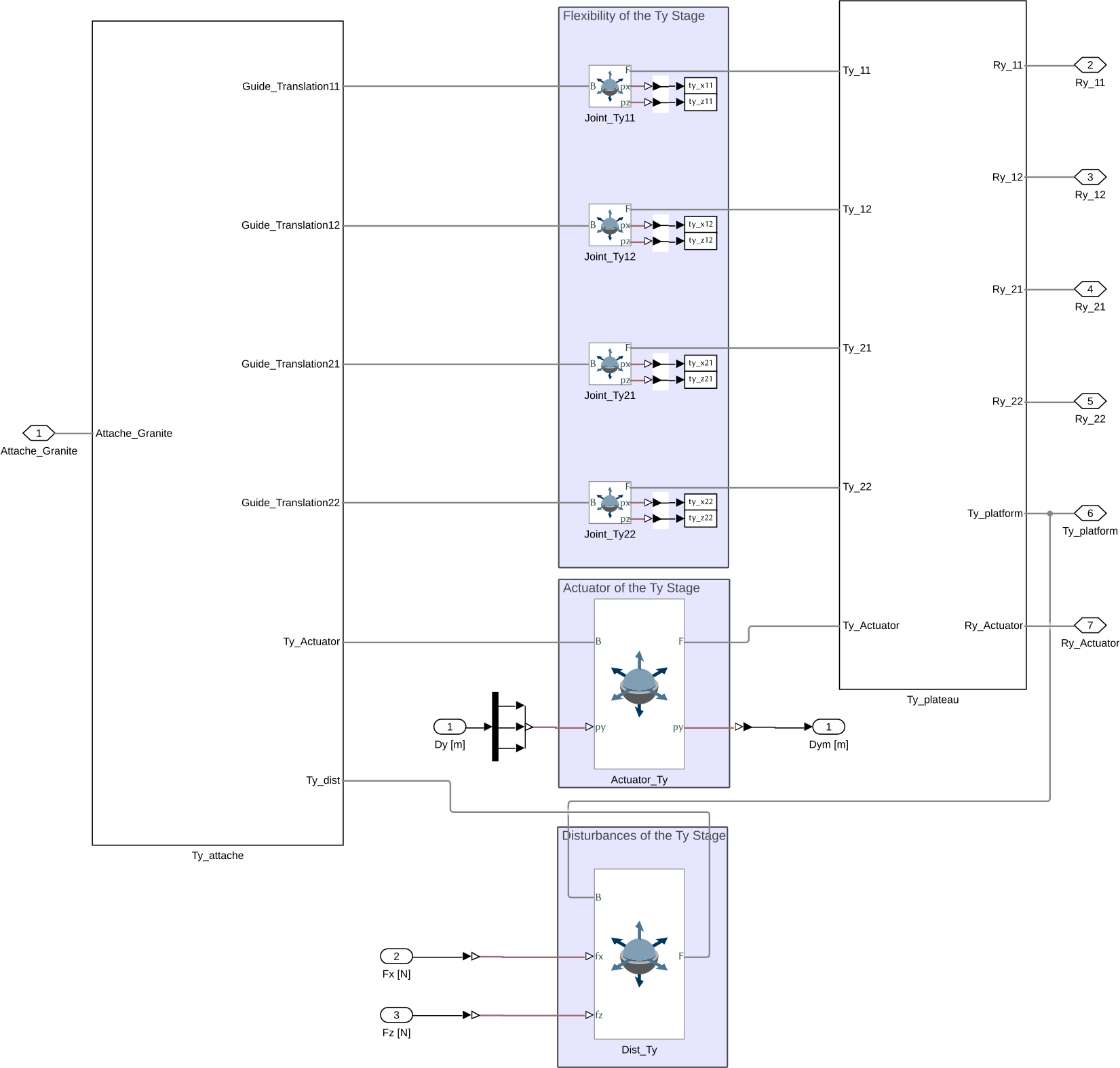
Figure 6: Simscape model for the Translation Stage
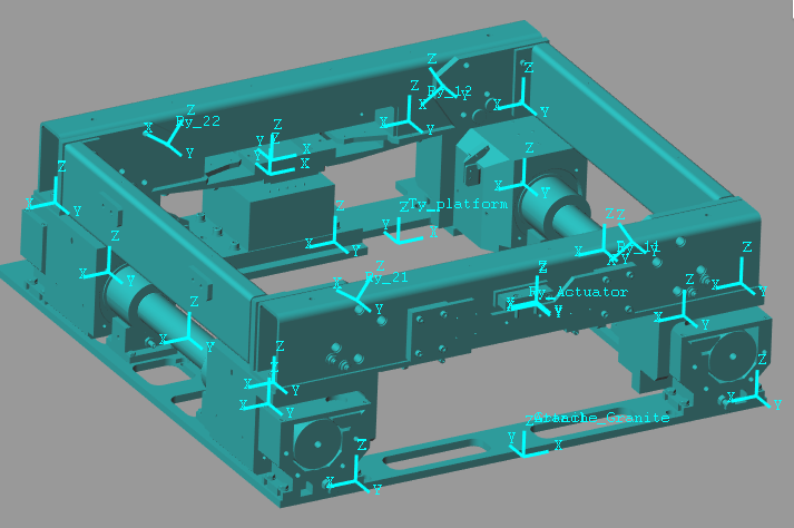
Figure 7: Simscape picture for the Translation Stage
Function description
function [ty] = initializeTy(args)
Optional Parameters
arguments
  args.type      char   {mustBeMember(args.type,{'none', 'rigid', 'flexible', 'modal-analysis', 'init'})} = 'flexible'
  args.Foffset logical {mustBeNumericOrLogical} = false
end
Structure initialization
First, we initialize the ty structure.
ty = struct();
Add Translation Stage Type
switch args.type
  case 'none'
    ty.type = 0;
  case 'rigid'
    ty.type = 1;
  case 'flexible'
    ty.type = 2;
  case 'modal-analysis'
    ty.type = 3;
  case 'init'
    ty.type = 4;
end
Material and Geometry
Define the density of the materials as well as the geometry (STEP files).
% Ty Granite frame
ty.granite_frame.density = 7800; % [kg/m3] => 43kg
ty.granite_frame.STEP    = './STEPS/Ty/Ty_Granite_Frame.STEP';

% Guide Translation Ty
ty.guide.density         = 7800; % [kg/m3] => 76kg
ty.guide.STEP            = './STEPS/ty/Ty_Guide.STEP';

% Ty - Guide_Translation12
ty.guide12.density       = 7800; % [kg/m3]
ty.guide12.STEP          = './STEPS/Ty/Ty_Guide_12.STEP';

% Ty - Guide_Translation11
ty.guide11.density       = 7800; % [kg/m3]
ty.guide11.STEP          = './STEPS/ty/Ty_Guide_11.STEP';

% Ty - Guide_Translation22
ty.guide22.density       = 7800; % [kg/m3]
ty.guide22.STEP          = './STEPS/ty/Ty_Guide_22.STEP';

% Ty - Guide_Translation21
ty.guide21.density       = 7800; % [kg/m3]
ty.guide21.STEP          = './STEPS/Ty/Ty_Guide_21.STEP';

% Ty - Plateau translation
ty.frame.density         = 7800; % [kg/m3]
ty.frame.STEP            = './STEPS/ty/Ty_Stage.STEP';

% Ty Stator Part
ty.stator.density        = 5400; % [kg/m3]
ty.stator.STEP           = './STEPS/ty/Ty_Motor_Stator.STEP';

% Ty Rotor Part
ty.rotor.density         = 5400; % [kg/m3]
ty.rotor.STEP            = './STEPS/ty/Ty_Motor_Rotor.STEP';
Stiffness and Damping properties
ty.K = [2e8; 1e8; 2e8; 6e7; 9e7; 6e7]; % [N/m, N*m/rad]
ty.C = [8e4; 5e4; 8e4; 2e4; 3e4; 2e4]; % [N/(m/s), N*m/(rad/s)]
Equilibrium position of the each joint.
if args.Foffset && ~strcmp(args.type, 'none') && ~strcmp(args.type, 'rigid') && ~strcmp(args.type, 'init')
  load('mat/Foffset.mat', 'Ftym');
  ty.Deq = -Ftym'./ty.K;
else
  ty.Deq = zeros(6,1);
end
Save the Structure
The ty structure is saved.
save('./mat/stages.mat', 'ty', '-append');
6 Tilt Stage
Simscape Model
The Simscape model of the Tilt stage is composed of:
- Two solid bodies for the two part of the stage
- Four 6-DOF joints to model the flexibility of the stage. These joints are virtually located along the rotation axis and are connecting the two solid bodies. These joints have some translation stiffness in the u-v-w directions aligned with the joint. The stiffness in rotation between the two solids is due to the fact that the 4 joints are connecting the two solids are different locations
- A Bushing Joint used for the Actuator. The Ry motion is imposed by the input.
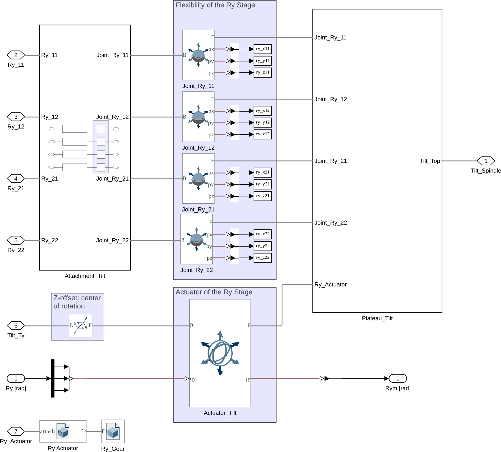
Figure 8: Simscape model for the Tilt Stage
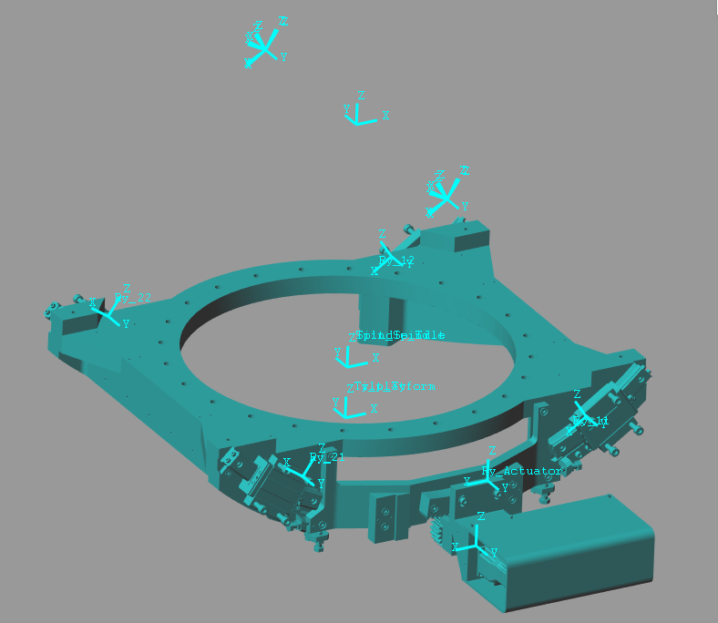
Figure 9: Simscape picture for the Tilt Stage
Function description
function [ry] = initializeRy(args)
Optional Parameters
arguments
  args.type          char    {mustBeMember(args.type,{'none', 'rigid', 'flexible', 'modal-analysis', 'init'})} = 'flexible'
  args.Foffset       logical {mustBeNumericOrLogical} = false
  args.Ry_init (1,1) double  {mustBeNumeric} = 0
end
Structure initialization
First, we initialize the ry structure.
ry = struct();
Add Tilt Type
switch args.type
  case 'none'
    ry.type = 0;
  case 'rigid'
    ry.type = 1;
  case 'flexible'
    ry.type = 2;
  case 'modal-analysis'
    ry.type = 3;
  case 'init'
    ry.type = 4;
end
Material and Geometry
Properties of the Material and link to the geometry of the Tilt stage.
% Ry - Guide for the tilt stage
ry.guide.density = 7800; % [kg/m3]
ry.guide.STEP    = './STEPS/ry/Tilt_Guide.STEP';

% Ry - Rotor of the motor
ry.rotor.density = 2400; % [kg/m3]
ry.rotor.STEP    = './STEPS/ry/Tilt_Motor_Axis.STEP';

% Ry - Motor
ry.motor.density = 3200; % [kg/m3]
ry.motor.STEP    = './STEPS/ry/Tilt_Motor.STEP';

% Ry - Plateau Tilt
ry.stage.density = 7800; % [kg/m3]
ry.stage.STEP    = './STEPS/ry/Tilt_Stage.STEP';
Z-Offset so that the center of rotation matches the sample center;
ry.z_offset = 0.58178; % [m]
ry.Ry_init = args.Ry_init; % [rad]
Stiffness and Damping properties
ry.K = [3.8e8; 4e8; 3.8e8; 1.2e8; 6e4; 1.2e8];
ry.C = [1e5;   1e5; 1e5;   3e4;   1e3; 3e4];
Equilibrium position of the each joint.
if args.Foffset && ~strcmp(args.type, 'none') && ~strcmp(args.type, 'rigid') && ~strcmp(args.type, 'init')
  load('mat/Foffset.mat', 'Fym');
  ry.Deq = -Fym'./ry.K;
else
  ry.Deq = zeros(6,1);
end
Save the Structure
The ry structure is saved.
save('./mat/stages.mat', 'ry', '-append');
7 Spindle
Simscape Model
The Simscape model of the Spindle is composed of:
- Two rigid bodies: the stator and the rotor
- A Bushing Joint that is used both as the actuator (the Rz motion is imposed by the input) and as the force perturbation in the Z direction.
- The Bushing joint has some flexibility in the X-Y-Z directions as well as in Rx and Ry rotations
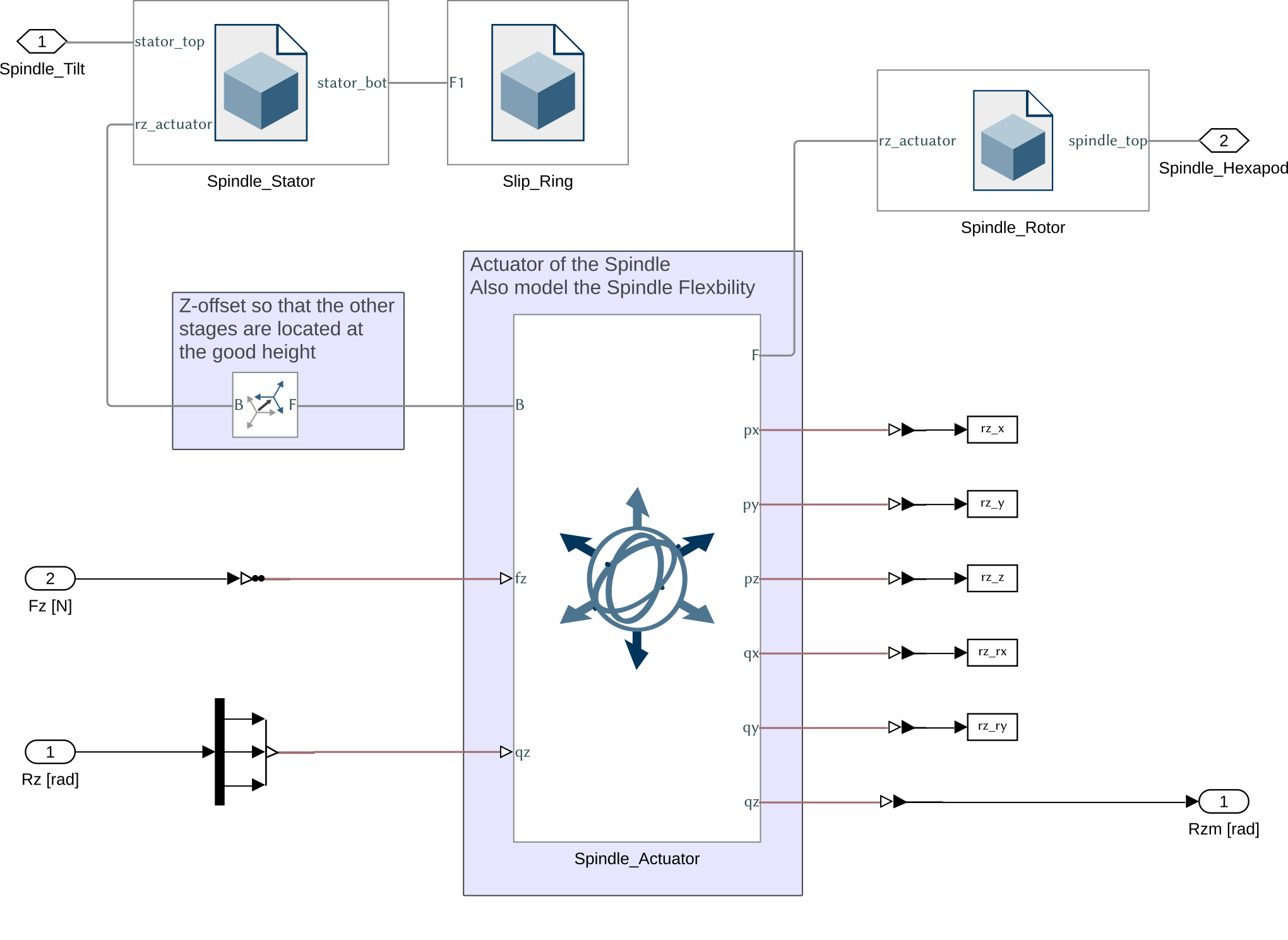
Figure 10: Simscape model for the Spindle
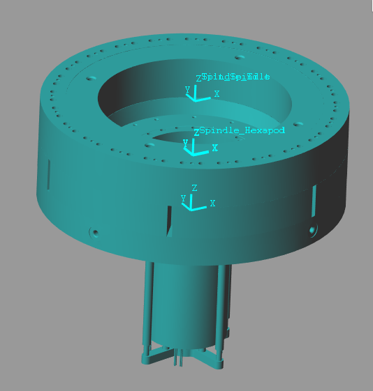
Figure 11: Simscape picture for the Spindle
Function description
function [rz] = initializeRz(args)
Optional Parameters
arguments
  args.type    char    {mustBeMember(args.type,{'none', 'rigid', 'flexible', 'modal-analysis', 'init'})} = 'flexible'
  args.Foffset logical {mustBeNumericOrLogical} = false
end
Structure initialization
First, we initialize the rz structure.
rz = struct();
Add Spindle Type
switch args.type
  case 'none'
    rz.type = 0;
  case 'rigid'
    rz.type = 1;
  case 'flexible'
    rz.type = 2;
  case 'modal-analysis'
    rz.type = 3;
  case 'init'
    rz.type = 4;
end
Material and Geometry
Properties of the Material and link to the geometry of the spindle.
% Spindle - Slip Ring
rz.slipring.density = 7800; % [kg/m3]
rz.slipring.STEP    = './STEPS/rz/Spindle_Slip_Ring.STEP';

% Spindle - Rotor
rz.rotor.density    = 7800; % [kg/m3]
rz.rotor.STEP       = './STEPS/rz/Spindle_Rotor.STEP';

% Spindle - Stator
rz.stator.density   = 7800; % [kg/m3]
rz.stator.STEP      = './STEPS/rz/Spindle_Stator.STEP';
Stiffness and Damping properties
rz.K = [7e8; 7e8; 2e9; 1e7; 1e7; 1e7];
rz.C = [4e4; 4e4; 7e4; 1e4; 1e4; 1e4];
Equilibrium position of the each joint.
if args.Foffset && ~strcmp(args.type, 'none') && ~strcmp(args.type, 'rigid') && ~strcmp(args.type, 'init')
  load('mat/Foffset.mat', 'Fzm');
  rz.Deq = -Fzm'./rz.K;
else
  rz.Deq = zeros(6,1);
end
Save the Structure
The rz structure is saved.
save('./mat/stages.mat', 'rz', '-append');
8 Micro Hexapod
Simscape Model

Figure 12: Simscape model for the Micro-Hexapod
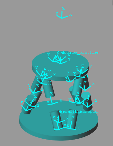
Figure 13: Simscape picture for the Micro-Hexapod
Function description
function [micro_hexapod] = initializeMicroHexapod(args)
Optional Parameters
arguments
    args.type      char   {mustBeMember(args.type,{'none', 'rigid', 'flexible', 'modal-analysis', 'init'})} = 'flexible'
    % initializeFramesPositions
    args.H    (1,1) double {mustBeNumeric, mustBePositive} = 350e-3
    args.MO_B (1,1) double {mustBeNumeric} = 270e-3
    % generateGeneralConfiguration
    args.FH  (1,1) double {mustBeNumeric, mustBePositive} = 50e-3
    args.FR  (1,1) double {mustBeNumeric, mustBePositive} = 175.5e-3
    args.FTh (6,1) double {mustBeNumeric} = [-10, 10, 120-10, 120+10, 240-10, 240+10]*(pi/180)
    args.MH  (1,1) double {mustBeNumeric, mustBePositive} = 45e-3
    args.MR  (1,1) double {mustBeNumeric, mustBePositive} = 118e-3
    args.MTh (6,1) double {mustBeNumeric} = [-60+10, 60-10, 60+10, 180-10, 180+10, -60-10]*(pi/180)
    % initializeStrutDynamics
    args.Ki (6,1) double {mustBeNumeric, mustBeNonnegative} = 2e7*ones(6,1)
    args.Ci (6,1) double {mustBeNumeric, mustBeNonnegative} = 1.4e3*ones(6,1)
    % initializeCylindricalPlatforms
    args.Fpm (1,1) double {mustBeNumeric, mustBePositive} = 10
    args.Fph (1,1) double {mustBeNumeric, mustBePositive} = 26e-3
    args.Fpr (1,1) double {mustBeNumeric, mustBePositive} = 207.5e-3
    args.Mpm (1,1) double {mustBeNumeric, mustBePositive} = 10
    args.Mph (1,1) double {mustBeNumeric, mustBePositive} = 26e-3
    args.Mpr (1,1) double {mustBeNumeric, mustBePositive} = 150e-3
    % initializeCylindricalStruts
    args.Fsm (1,1) double {mustBeNumeric, mustBePositive} = 1
    args.Fsh (1,1) double {mustBeNumeric, mustBePositive} = 100e-3
    args.Fsr (1,1) double {mustBeNumeric, mustBePositive} = 25e-3
    args.Msm (1,1) double {mustBeNumeric, mustBePositive} = 1
    args.Msh (1,1) double {mustBeNumeric, mustBePositive} = 100e-3
    args.Msr (1,1) double {mustBeNumeric, mustBePositive} = 25e-3
    % inverseKinematics
    args.AP  (3,1) double {mustBeNumeric} = zeros(3,1)
    args.ARB (3,3) double {mustBeNumeric} = eye(3)
    % Force that stiffness of each joint should apply at t=0
    args.Foffset      logical {mustBeNumericOrLogical} = false
end
Function content
micro_hexapod = initializeFramesPositions('H', args.H, 'MO_B', args.MO_B);
micro_hexapod = generateGeneralConfiguration(micro_hexapod, 'FH', args.FH, 'FR', args.FR, 'FTh', args.FTh, 'MH', args.MH, 'MR', args.MR, 'MTh', args.MTh);
micro_hexapod = computeJointsPose(micro_hexapod);
micro_hexapod = initializeStrutDynamics(micro_hexapod, 'Ki', args.Ki, 'Ci', args.Ci);
micro_hexapod = initializeCylindricalPlatforms(micro_hexapod, 'Fpm', args.Fpm, 'Fph', args.Fph, 'Fpr', args.Fpr, 'Mpm', args.Mpm, 'Mph', args.Mph, 'Mpr', args.Mpr);
micro_hexapod = initializeCylindricalStruts(micro_hexapod, 'Fsm', args.Fsm, 'Fsh', args.Fsh, 'Fsr', args.Fsr, 'Msm', args.Msm, 'Msh', args.Msh, 'Msr', args.Msr);
micro_hexapod = computeJacobian(micro_hexapod);
[Li, dLi] = inverseKinematics(micro_hexapod, 'AP', args.AP, 'ARB', args.ARB);
micro_hexapod.Li = Li;
micro_hexapod.dLi = dLi;
Equilibrium position of the each joint.
if args.Foffset && ~strcmp(args.type, 'none') && ~strcmp(args.type, 'rigid') && ~strcmp(args.type, 'init')
  load('mat/Foffset.mat', 'Fhm');
  micro_hexapod.dLeq = -Fhm'./args.Ki;
else
  micro_hexapod.dLeq = zeros(6,1);
end
Add Type
switch args.type
  case 'none'
    micro_hexapod.type = 0;
  case 'rigid'
    micro_hexapod.type = 1;
  case 'flexible'
    micro_hexapod.type = 2;
  case 'modal-analysis'
    micro_hexapod.type = 3;
  case 'init'
    micro_hexapod.type = 4;
end
Save the Structure
The micro_hexapod structure is saved.
save('./mat/stages.mat', 'micro_hexapod', '-append');
9 Center of gravity compensation
Simscape Model
The Simscape model of the Center of gravity compensator is composed of:
- One main solid that is connected to two other solids (the masses to position of center of mass) through two revolute joints
- The angle of both revolute joints is set by the input
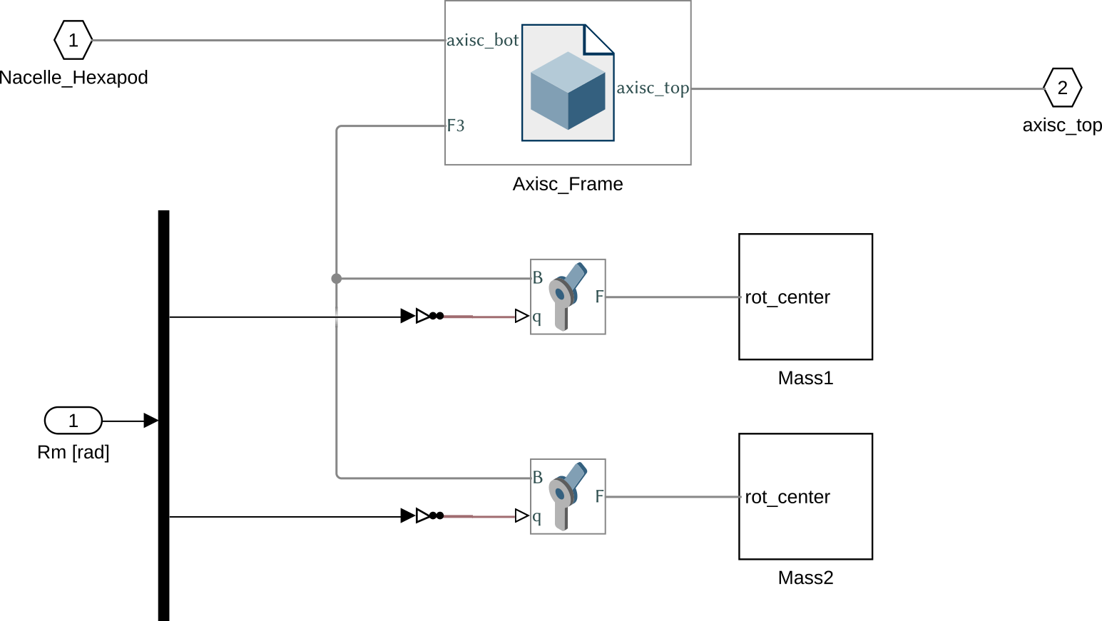
Figure 14: Simscape model for the Center of Mass compensation system
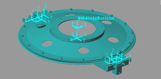
Figure 15: Simscape picture for the Center of Mass compensation system
Function description
function [axisc] = initializeAxisc(args)
Optional Parameters
arguments
  args.type char {mustBeMember(args.type,{'none', 'rigid', 'flexible'})} = 'flexible'
end
Structure initialization
First, we initialize the axisc structure.
axisc = struct();
Add Type
switch args.type
  case 'none'
    axisc.type = 0;
  case 'rigid'
    axisc.type = 1;
  case 'flexible'
    axisc.type = 2;
end
Material and Geometry
Properties of the Material and link to the geometry files.
% Structure
axisc.structure.density = 3400; % [kg/m3]
axisc.structure.STEP    = './STEPS/axisc/axisc_structure.STEP';

% Wheel
axisc.wheel.density     = 2700; % [kg/m3]
axisc.wheel.STEP        = './STEPS/axisc/axisc_wheel.STEP';

% Mass
axisc.mass.density      = 7800; % [kg/m3]
axisc.mass.STEP         = './STEPS/axisc/axisc_mass.STEP';

% Gear
axisc.gear.density      = 7800; % [kg/m3]
axisc.gear.STEP         = './STEPS/axisc/axisc_gear.STEP';
Save the Structure
The axisc structure is saved.
save('./mat/stages.mat', 'axisc', '-append');
10 Mirror
Simscape Model
The Simscape Model of the mirror is just a solid body.
The output mirror_center corresponds to the center of the Sphere and is the point of measurement for the metrology
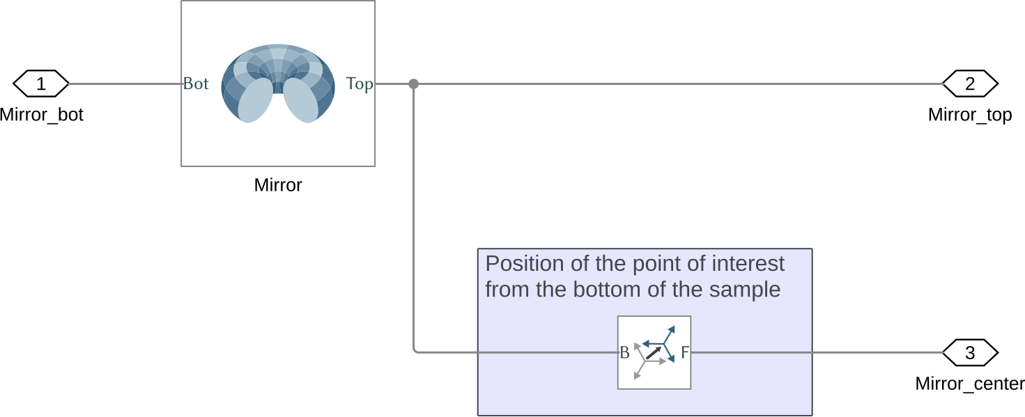
Figure 16: Simscape model for the Mirror
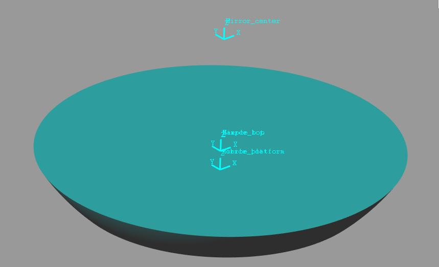
Figure 17: Simscape picture for the Mirror
Function description
function [] = initializeMirror(args)
Optional Parameters
arguments
  args.type        char   {mustBeMember(args.type,{'none', 'rigid'})} = 'rigid'
  args.shape       char   {mustBeMember(args.shape,{'spherical', 'conical'})} = 'spherical'
  args.angle (1,1) double {mustBeNumeric, mustBePositive} = 45 % [deg]
end
Structure initialization
First, we initialize the mirror structure.
mirror = struct();
Add Mirror Type
switch args.type
  case 'none'
    mirror.type = 0;
  case 'rigid'
    mirror.type = 1;
end
Material and Geometry
We define the geometrical values.
mirror.h = 0.05; % Height of the mirror [m]

mirror.thickness = 0.025; % Thickness of the plate supporting the sample [m]

mirror.hole_rad = 0.120; % radius of the hole in the mirror [m]

mirror.support_rad = 0.1; % radius of the support plate [m]

% point of interest offset in z (above the top surfave) [m]
switch args.type
  case 'none'
    mirror.jacobian = 0.20;
  case 'rigid'
    mirror.jacobian = 0.20 - mirror.h;
end

mirror.rad = 0.180; % radius of the mirror (at the bottom surface) [m]
mirror.density = 2400; % Density of the material [kg/m3]
mirror.cone_length = mirror.rad*tand(args.angle)+mirror.h+mirror.jacobian; % Distance from Apex point of the cone to jacobian point
Now we define the Shape of the mirror. We first start with the internal part.
mirror.shape = [...
    0 mirror.h-mirror.thickness
    mirror.hole_rad mirror.h-mirror.thickness; ...
    mirror.hole_rad 0; ...
    mirror.rad 0 ...
];
Then, we define the reflective used part of the mirror.
if strcmp(args.shape, 'spherical')
    mirror.sphere_radius = sqrt((mirror.jacobian+mirror.h)^2+mirror.rad^2); % Radius of the sphere [mm]

    for z = linspace(0, mirror.h, 101)
        mirror.shape = [mirror.shape; sqrt(mirror.sphere_radius^2-(z-mirror.jacobian-mirror.h)^2) z];
    end
elseif strcmp(args.shape, 'conical')
    mirror.shape = [mirror.shape; mirror.rad+mirror.h/tand(args.angle) mirror.h];
else
    error('Shape should be either conical or spherical');
end
Finally, we close the shape.
mirror.shape = [mirror.shape; 0 mirror.h];
Save the Structure
The mirror structure is saved.
save('./mat/stages.mat', 'mirror', '-append');
11 Nano Hexapod
Simscape Model
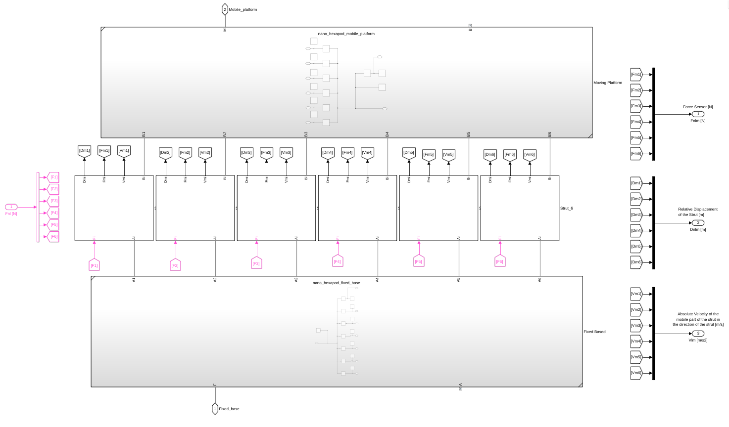
Figure 18: Simscape model for the Nano Hexapod
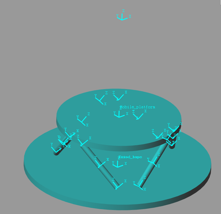
Figure 19: Simscape picture for the Nano Hexapod
Function description
function [nano_hexapod] = initializeNanoHexapod(args)
Optional Parameters
arguments
    args.type      char   {mustBeMember(args.type,{'none', 'rigid', 'flexible'})} = 'flexible'
    % initializeFramesPositions
    args.H    (1,1) double {mustBeNumeric, mustBePositive} = 90e-3
    args.MO_B (1,1) double {mustBeNumeric} = 175e-3
    % generateGeneralConfiguration
    args.FH  (1,1) double {mustBeNumeric, mustBePositive} = 15e-3
    args.FR  (1,1) double {mustBeNumeric, mustBePositive} = 100e-3
    args.FTh (6,1) double {mustBeNumeric} = [-10, 10, 120-10, 120+10, 240-10, 240+10]*(pi/180)
    args.MH  (1,1) double {mustBeNumeric, mustBePositive} = 15e-3
    args.MR  (1,1) double {mustBeNumeric, mustBePositive} = 90e-3
    args.MTh (6,1) double {mustBeNumeric} = [-60+10, 60-10, 60+10, 180-10, 180+10, -60-10]*(pi/180)
    % initializeStrutDynamics
    args.actuator  char   {mustBeMember(args.actuator,{'piezo', 'lorentz'})} = 'piezo'
    % initializeCylindricalPlatforms
    args.Fpm (1,1) double {mustBeNumeric, mustBePositive} = 1
    args.Fph (1,1) double {mustBeNumeric, mustBePositive} = 10e-3
    args.Fpr (1,1) double {mustBeNumeric, mustBePositive} = 150e-3
    args.Mpm (1,1) double {mustBeNumeric, mustBePositive} = 1
    args.Mph (1,1) double {mustBeNumeric, mustBePositive} = 10e-3
    args.Mpr (1,1) double {mustBeNumeric, mustBePositive} = 100e-3
    % initializeCylindricalStruts
    args.Fsm (1,1) double {mustBeNumeric, mustBePositive} = 0.1
    args.Fsh (1,1) double {mustBeNumeric, mustBePositive} = 50e-3
    args.Fsr (1,1) double {mustBeNumeric, mustBePositive} = 5e-3
    args.Msm (1,1) double {mustBeNumeric, mustBePositive} = 0.1
    args.Msh (1,1) double {mustBeNumeric, mustBePositive} = 50e-3
    args.Msr (1,1) double {mustBeNumeric, mustBePositive} = 5e-3
    % inverseKinematics
    args.AP  (3,1) double {mustBeNumeric} = zeros(3,1)
    args.ARB (3,3) double {mustBeNumeric} = eye(3)
    % Equilibrium position of each leg
    args.dLeq (6,1) double {mustBeNumeric} = zeros(6,1)
end
Function content
nano_hexapod = initializeFramesPositions('H', args.H, 'MO_B', args.MO_B);
nano_hexapod = generateGeneralConfiguration(nano_hexapod, 'FH', args.FH, 'FR', args.FR, 'FTh', args.FTh, 'MH', args.MH, 'MR', args.MR, 'MTh', args.MTh);
nano_hexapod = computeJointsPose(nano_hexapod);
if strcmp(args.actuator, 'piezo')
    nano_hexapod = initializeStrutDynamics(nano_hexapod, 'Ki', 1e7*ones(6,1), 'Ci', 1e2*ones(6,1));
elseif strcmp(args.actuator, 'lorentz')
    nano_hexapod = initializeStrutDynamics(nano_hexapod, 'Ki', 1e4*ones(6,1), 'Ci', 1e2*ones(6,1));
else
    error('args.actuator should be piezo or lorentz');
end
nano_hexapod = initializeCylindricalPlatforms(nano_hexapod, 'Fpm', args.Fpm, 'Fph', args.Fph, 'Fpr', args.Fpr, 'Mpm', args.Mpm, 'Mph', args.Mph, 'Mpr', args.Mpr);
nano_hexapod = initializeCylindricalStruts(nano_hexapod, 'Fsm', args.Fsm, 'Fsh', args.Fsh, 'Fsr', args.Fsr, 'Msm', args.Msm, 'Msh', args.Msh, 'Msr', args.Msr);
nano_hexapod = computeJacobian(nano_hexapod);
[Li, dLi] = inverseKinematics(nano_hexapod, 'AP', args.AP, 'ARB', args.ARB);
nano_hexapod.Li = Li;
nano_hexapod.dLi = dLi;
nano_hexapod.dLeq = args.dLeq;
Add Type
switch args.type
  case 'none'
    nano_hexapod.type = 0;
  case 'rigid'
    nano_hexapod.type = 1;
  case 'flexible'
    nano_hexapod.type = 2;
end
Save the Structure
save('./mat/stages.mat', 'nano_hexapod', '-append');
12 Sample
Simscape Model
The Simscape model of the sample environment is composed of:
- A rigid transform that can be used to translate the sample (position offset)
- A cartesian joint to add some flexibility to the sample environment mount
- A solid that represent the sample
- An input is added to apply some external forces and torques at the center of the sample environment. This could be the case for cable forces for instance.
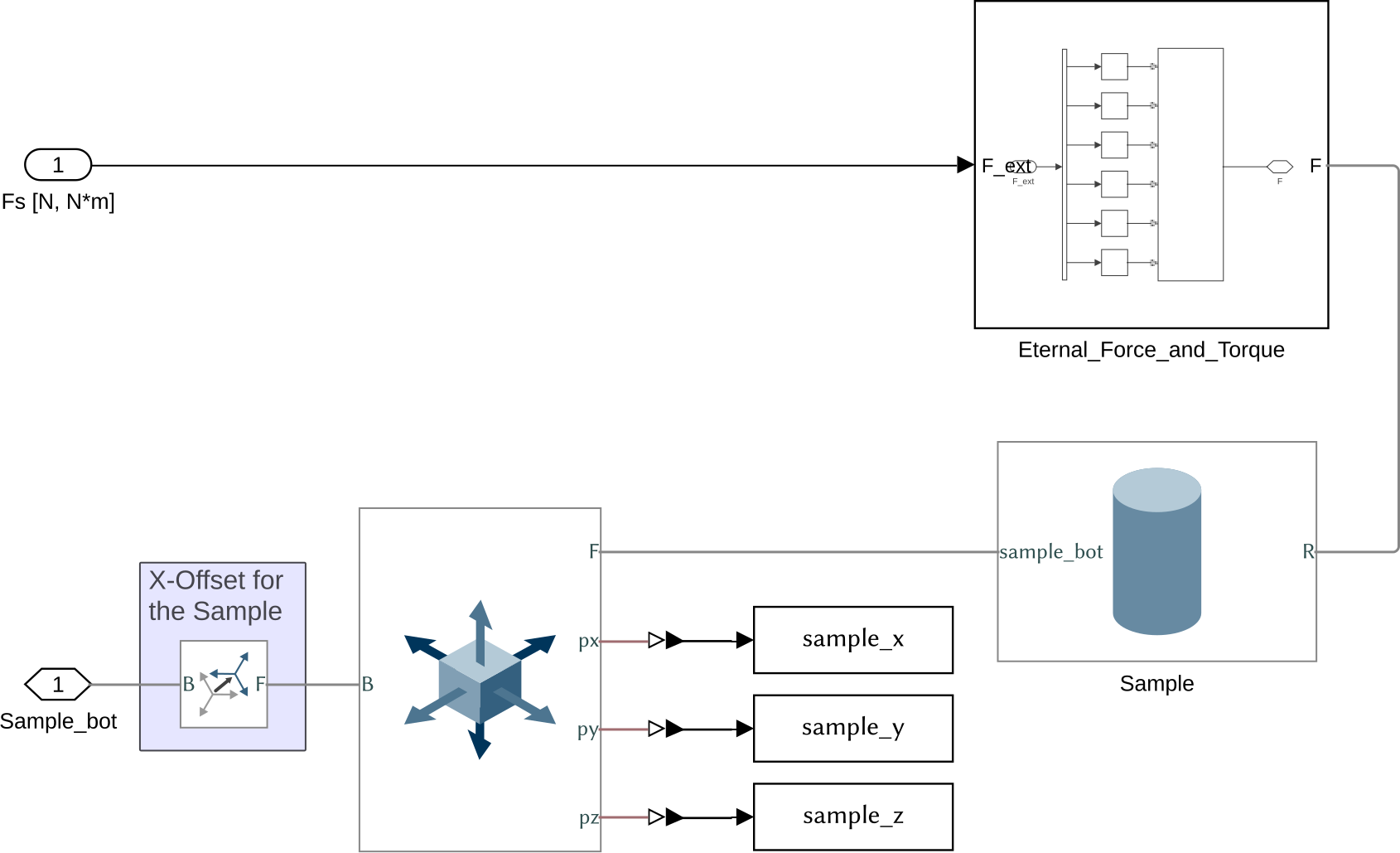
Figure 20: Simscape model for the Sample
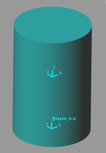
Figure 21: Simscape picture for the Sample
Function description
function [sample] = initializeSample(args)
Optional Parameters
arguments
  args.type         char    {mustBeMember(args.type,{'rigid', 'flexible', 'none', 'init'})} = 'flexible'
  args.radius (1,1) double  {mustBeNumeric, mustBePositive} = 0.1 % [m]
  args.height (1,1) double  {mustBeNumeric, mustBePositive} = 0.3 % [m]
  args.mass   (1,1) double  {mustBeNumeric, mustBePositive} = 50 % [kg]
  args.freq   (1,1) double  {mustBeNumeric, mustBePositive} = 100 % [Hz]
  args.offset (1,1) double  {mustBeNumeric} = 0 % [m]
  args.Foffset      logical {mustBeNumericOrLogical} = false
end
Structure initialization
First, we initialize the sample structure.
sample = struct();
Add Sample Type
switch args.type
  case 'none'
    sample.type = 0;
  case 'rigid'
    sample.type = 1;
  case 'flexible'
    sample.type = 2;
  case 'init'
    sample.type = 3;
end
Material and Geometry
We define the geometrical parameters of the sample as well as its mass and position.
sample.radius = args.radius; % [m]
sample.height = args.height; % [m]
sample.mass   = args.mass; % [kg]
sample.offset = args.offset; % [m]
Stiffness and Damping properties
sample.K = ones(3,1) * sample.mass * (2*pi * args.freq)^2; % [N/m]
sample.C = 0.1 * sqrt(sample.K*sample.mass); % [N/(m/s)]
Equilibrium position of the each joint.
if args.Foffset && ~strcmp(args.type, 'none') && ~strcmp(args.type, 'rigid') && ~strcmp(args.type, 'init')
  load('mat/Foffset.mat', 'Fsm');
  sample.Deq = -Fsm'./sample.K;
else
  sample.Deq = zeros(3,1);
end
Save the Structure
The sample structure is saved.
save('./mat/stages.mat', 'sample', '-append');
13 Initialize Controller
Function Declaration and Documentation
function [] = initializeController(args)
Optional Parameters
arguments
  args.type char {mustBeMember(args.type,{'open-loop', 'iff', 'dvf', 'hac-dvf', 'ref-track-L', 'ref-track-iff-L', 'cascade-hac-lac', 'hac-iff'})} = 'open-loop'
end
Structure initialization
First, we initialize the controller structure.
controller = struct();
Controller Type
switch args.type
  case 'open-loop'
    controller.type = 1;
  case 'dvf'
    controller.type = 2;
  case 'iff'
    controller.type = 3;
  case 'hac-dvf'
    controller.type = 4;
  case 'ref-track-L'
    controller.type = 5;
  case 'ref-track-iff-L'
    controller.type = 6;
  case 'cascade-hac-lac'
    controller.type = 7;
  case 'hac-iff'
    controller.type = 8;
end
Save the Structure
The controller structure is saved.
save('./mat/controller.mat', 'controller');
14 Generate Reference Signals
Function Declaration and Documentation
function [ref] = initializeReferences(args)
Optional Parameters
arguments
    % Sampling Frequency [s]
    args.Ts           (1,1) double {mustBeNumeric, mustBePositive} = 1e-3
    % Maximum simulation time [s]
    args.Tmax         (1,1) double {mustBeNumeric, mustBePositive} = 100
    % Either "constant" / "triangular" / "sinusoidal"
    args.Dy_type      char {mustBeMember(args.Dy_type,{'constant', 'triangular', 'sinusoidal'})} = 'constant'
    % Amplitude of the displacement [m]
    args.Dy_amplitude (1,1) double {mustBeNumeric} = 0
    % Period of the displacement [s]
    args.Dy_period    (1,1) double {mustBeNumeric, mustBePositive} = 1
    % Either "constant" / "triangular" / "sinusoidal"
    args.Ry_type      char {mustBeMember(args.Ry_type,{'constant', 'triangular', 'sinusoidal'})} = 'constant'
    % Amplitude [rad]
    args.Ry_amplitude (1,1) double {mustBeNumeric} = 0
    % Period of the displacement [s]
    args.Ry_period    (1,1) double {mustBeNumeric, mustBePositive} = 1
    % Either "constant" / "rotating"
    args.Rz_type      char {mustBeMember(args.Rz_type,{'constant', 'rotating'})} = 'constant'
    % Initial angle [rad]
    args.Rz_amplitude (1,1) double {mustBeNumeric} = 0
    % Period of the rotating [s]
    args.Rz_period    (1,1) double {mustBeNumeric, mustBePositive} = 1
    % For now, only constant is implemented
    args.Dh_type      char {mustBeMember(args.Dh_type,{'constant'})} = 'constant'
    % Initial position [m,m,m,rad,rad,rad] of the top platform (Pitch-Roll-Yaw Euler angles)
    args.Dh_pos       (6,1) double {mustBeNumeric} = zeros(6, 1), ...
    % For now, only constant is implemented
    args.Rm_type      char {mustBeMember(args.Rm_type,{'constant'})} = 'constant'
    % Initial position of the two masses
    args.Rm_pos       (2,1) double {mustBeNumeric} = [0; pi]
    % For now, only constant is implemented
    args.Dn_type      char {mustBeMember(args.Dn_type,{'constant'})} = 'constant'
    % Initial position [m,m,m,rad,rad,rad] of the top platform
    args.Dn_pos       (6,1) double {mustBeNumeric} = zeros(6,1)
end
Initialize Parameters
%% Set Sampling Time
Ts = args.Ts;
Tmax = args.Tmax;

%% Low Pass Filter to filter out the references
s = zpk('s');
w0 = 2*pi*10;
xi = 1;
H_lpf = 1/(1 + 2*xi/w0*s + s^2/w0^2);
Translation Stage
%% Translation stage - Dy
t = 0:Ts:Tmax; % Time Vector [s]
Dy   = zeros(length(t), 1);
Dyd  = zeros(length(t), 1);
Dydd = zeros(length(t), 1);
switch args.Dy_type
  case 'constant'
    Dy(:)   = args.Dy_amplitude;
    Dyd(:)  = 0;
    Dydd(:) = 0;
  case 'triangular'
    % This is done to unsure that we start with no displacement
    Dy_raw = args.Dy_amplitude*sawtooth(2*pi*t/args.Dy_period,1/2);
    i0 = find(t>=args.Dy_period/4,1);
    Dy(1:end-i0+1) = Dy_raw(i0:end);
    Dy(end-i0+2:end) = Dy_raw(end); % we fix the last value

    % The signal is filtered out
    Dy   = lsim(H_lpf,     Dy, t);
    Dyd  = lsim(H_lpf*s,   Dy, t);
    Dydd = lsim(H_lpf*s^2, Dy, t);
  case 'sinusoidal'
    Dy(:) = args.Dy_amplitude*sin(2*pi/args.Dy_period*t);
    Dyd   = args.Dy_amplitude*2*pi/args.Dy_period*cos(2*pi/args.Dy_period*t);
    Dydd  = -args.Dy_amplitude*(2*pi/args.Dy_period)^2*sin(2*pi/args.Dy_period*t);
  otherwise
    warning('Dy_type is not set correctly');
end

Dy = struct('time', t, 'signals', struct('values', Dy), 'deriv', Dyd, 'dderiv', Dydd);
Tilt Stage
%% Tilt Stage - Ry
t = 0:Ts:Tmax; % Time Vector [s]
Ry   = zeros(length(t), 1);
Ryd  = zeros(length(t), 1);
Rydd = zeros(length(t), 1);

switch args.Ry_type
  case 'constant'
    Ry(:) = args.Ry_amplitude;
    Ryd(:)   = 0;
    Rydd(:)  = 0;
  case 'triangular'
    Ry_raw = args.Ry_amplitude*sawtooth(2*pi*t/args.Ry_period,1/2);
    i0 = find(t>=args.Ry_period/4,1);
    Ry(1:end-i0+1) = Ry_raw(i0:end);
    Ry(end-i0+2:end) = Ry_raw(end); % we fix the last value

    % The signal is filtered out
    Ry   = lsim(H_lpf,     Ry, t);
    Ryd  = lsim(H_lpf*s,   Ry, t);
    Rydd = lsim(H_lpf*s^2, Ry, t);
  case 'sinusoidal'
    Ry(:) = args.Ry_amplitude*sin(2*pi/args.Ry_period*t);

    Ryd  = args.Ry_amplitude*2*pi/args.Ry_period*cos(2*pi/args.Ry_period*t);
    Rydd = -args.Ry_amplitude*(2*pi/args.Ry_period)^2*sin(2*pi/args.Ry_period*t);
  otherwise
    warning('Ry_type is not set correctly');
end

Ry = struct('time', t, 'signals', struct('values', Ry), 'deriv', Ryd, 'dderiv', Rydd);
Spindle
%% Spindle - Rz
t = 0:Ts:Tmax; % Time Vector [s]
Rz   = zeros(length(t), 1);
Rzd  = zeros(length(t), 1);
Rzdd = zeros(length(t), 1);

switch args.Rz_type
  case 'constant'
    Rz(:)   = args.Rz_amplitude;
    Rzd(:)  = 0;
    Rzdd(:) = 0;
  case 'rotating'
    Rz(:) = 2*pi/args.Rz_period*t;

    % The signal is filtered out
    Rz   = lsim(H_lpf,     Rz, t);
    Rzd  = lsim(H_lpf*s,   Rz, t);
    Rzdd = lsim(H_lpf*s^2, Rz, t);

    % We add the angle offset
    Rz = Rz + args.Rz_amplitude;
  otherwise
    warning('Rz_type is not set correctly');
end

Rz = struct('time', t, 'signals', struct('values', Rz), 'deriv', Rzd, 'dderiv', Rzdd);
Micro Hexapod
%% Micro-Hexapod
t = [0, Ts];
Dh = zeros(length(t), 6);
Dhl = zeros(length(t), 6);

switch args.Dh_type
  case 'constant'
    Dh = [args.Dh_pos, args.Dh_pos];

    load('mat/stages.mat', 'micro_hexapod');

    AP = [args.Dh_pos(1) ; args.Dh_pos(2) ; args.Dh_pos(3)];

    tx = args.Dh_pos(4);
    ty = args.Dh_pos(5);
    tz = args.Dh_pos(6);

    ARB = [cos(tz) -sin(tz) 0;
           sin(tz)  cos(tz) 0;
           0        0       1]*...
          [ cos(ty) 0 sin(ty);
            0       1 0;
           -sin(ty) 0 cos(ty)]*...
          [1 0        0;
           0 cos(tx) -sin(tx);
           0 sin(tx)  cos(tx)];

    [~, Dhl] = inverseKinematics(micro_hexapod, 'AP', AP, 'ARB', ARB);
    Dhl = [Dhl, Dhl];
  otherwise
    warning('Dh_type is not set correctly');
end

Dh = struct('time', t, 'signals', struct('values', Dh));
Dhl = struct('time', t, 'signals', struct('values', Dhl));
Axis Compensation
%% Axis Compensation - Rm
t = [0, Ts];

Rm = [args.Rm_pos, args.Rm_pos];
Rm = struct('time', t, 'signals', struct('values', Rm));
Nano Hexapod
%% Nano-Hexapod
t = [0, Ts];
Dn = zeros(length(t), 6);

switch args.Dn_type
  case 'constant'
    Dn = [args.Dn_pos, args.Dn_pos];

    load('mat/stages.mat', 'nano_hexapod');

    AP = [args.Dn_pos(1) ; args.Dn_pos(2) ; args.Dn_pos(3)];

    tx = args.Dn_pos(4);
    ty = args.Dn_pos(5);
    tz = args.Dn_pos(6);

    ARB = [cos(tz) -sin(tz) 0;
           sin(tz)  cos(tz) 0;
           0        0       1]*...
          [ cos(ty) 0 sin(ty);
            0       1 0;
           -sin(ty) 0 cos(ty)]*...
          [1 0        0;
           0 cos(tx) -sin(tx);
           0 sin(tx)  cos(tx)];

    [~, Dnl] = inverseKinematics(nano_hexapod, 'AP', AP, 'ARB', ARB);
    Dnl = [Dnl, Dnl];
  otherwise
    warning('Dn_type is not set correctly');
end

Dn = struct('time', t, 'signals', struct('values', Dn));
Dnl = struct('time', t, 'signals', struct('values', Dnl));
Save
    %% Save
    save('./mat/nass_references.mat', 'Dy', 'Ry', 'Rz', 'Dh', 'Dhl', 'Rm', 'Dn', 'Dnl', 'Ts');
end
15 Initialize Disturbances
Function Declaration and Documentation
function [] = initializeDisturbances(args)
% initializeDisturbances - Initialize the disturbances
%
% Syntax: [] = initializeDisturbances(args)
%
% Inputs:
%    - args -
Optional Parameters
arguments
    % Global parameter to enable or disable the disturbances
    args.enable logical {mustBeNumericOrLogical} = true
    % Ground Motion - X direction
    args.Dwx logical {mustBeNumericOrLogical} = true
    % Ground Motion - Y direction
    args.Dwy logical {mustBeNumericOrLogical} = true
    % Ground Motion - Z direction
    args.Dwz logical {mustBeNumericOrLogical} = true
    % Translation Stage - X direction
    args.Fty_x logical {mustBeNumericOrLogical} = true
    % Translation Stage - Z direction
    args.Fty_z logical {mustBeNumericOrLogical} = true
    % Spindle - Z direction
    args.Frz_z logical {mustBeNumericOrLogical} = true
end
Load Data
load('./mat/dist_psd.mat', 'dist_f');
We remove the first frequency point that usually is very large.
Parameters
We define some parameters that will be used in the algorithm.
Fs = 2*dist_f.f(end);      % Sampling Frequency of data is twice the maximum frequency of the PSD vector [Hz]
N  = 2*length(dist_f.f);   % Number of Samples match the one of the wanted PSD
T0 = N/Fs;                 % Signal Duration [s]
df = 1/T0;                 % Frequency resolution of the DFT [Hz]
                           % Also equal to (dist_f.f(2)-dist_f.f(1))
t = linspace(0, T0, N+1)'; % Time Vector [s]
Ts = 1/Fs;                 % Sampling Time [s]
Ground Motion
phi = dist_f.psd_gm;
C = zeros(N/2,1);
for i = 1:N/2
  C(i) = sqrt(phi(i)*df);
end
if args.Dwx && args.enable
  rng(111);
  theta = 2*pi*rand(N/2,1); % Generate random phase [rad]
  Cx = [0 ; C.*complex(cos(theta),sin(theta))];
  Cx = [Cx; flipud(conj(Cx(2:end)))];;
  Dwx = N/sqrt(2)*ifft(Cx); % Ground Motion - x direction [m]
else
  Dwx = zeros(length(t), 1);
end
if args.Dwy && args.enable
  rng(112);
  theta = 2*pi*rand(N/2,1); % Generate random phase [rad]
  Cx = [0 ; C.*complex(cos(theta),sin(theta))];
  Cx = [Cx; flipud(conj(Cx(2:end)))];;
  Dwy = N/sqrt(2)*ifft(Cx); % Ground Motion - y direction [m]
else
  Dwy = zeros(length(t), 1);
end
if args.Dwy && args.enable
  rng(113);
  theta = 2*pi*rand(N/2,1); % Generate random phase [rad]
  Cx = [0 ; C.*complex(cos(theta),sin(theta))];
  Cx = [Cx; flipud(conj(Cx(2:end)))];;
  Dwz = N/sqrt(2)*ifft(Cx); % Ground Motion - z direction [m]
else
  Dwz = zeros(length(t), 1);
end
Translation Stage - X direction
if args.Fty_x && args.enable
  phi = dist_f.psd_ty; % TODO - we take here the vertical direction which is wrong but approximate
  C = zeros(N/2,1);
  for i = 1:N/2
    C(i) = sqrt(phi(i)*df);
  end
  rng(121);
  theta = 2*pi*rand(N/2,1); % Generate random phase [rad]
  Cx = [0 ; C.*complex(cos(theta),sin(theta))];
  Cx = [Cx; flipud(conj(Cx(2:end)))];;
  u = N/sqrt(2)*ifft(Cx); % Disturbance Force Ty x [N]
  Fty_x = u;
else
  Fty_x = zeros(length(t), 1);
end
Translation Stage - Z direction
if args.Fty_z && args.enable
  phi = dist_f.psd_ty;
  C = zeros(N/2,1);
  for i = 1:N/2
    C(i) = sqrt(phi(i)*df);
  end
  rng(122);
  theta = 2*pi*rand(N/2,1); % Generate random phase [rad]
  Cx = [0 ; C.*complex(cos(theta),sin(theta))];
  Cx = [Cx; flipud(conj(Cx(2:end)))];;
  u = N/sqrt(2)*ifft(Cx); % Disturbance Force Ty z [N]
  Fty_z = u;
else
  Fty_z = zeros(length(t), 1);
end
Spindle - Z direction
if args.Frz_z && args.enable
  phi = dist_f.psd_rz;
  C = zeros(N/2,1);
  for i = 1:N/2
    C(i) = sqrt(phi(i)*df);
  end
  rng(131);
  theta = 2*pi*rand(N/2,1); % Generate random phase [rad]
  Cx = [0 ; C.*complex(cos(theta),sin(theta))];
  Cx = [Cx; flipud(conj(Cx(2:end)))];;
  u = N/sqrt(2)*ifft(Cx); % Disturbance Force Rz z [N]
  Frz_z = u;
else
  Frz_z = zeros(length(t), 1);
end
Direct Forces
u = zeros(length(t), 6);
Fd = u;
Set initial value to zero
Dwx    = Dwx   - Dwx(1);
Dwy    = Dwy   - Dwy(1);
Dwz    = Dwz   - Dwz(1);
Fty_x  = Fty_x - Fty_x(1);
Fty_z  = Fty_z - Fty_z(1);
Frz_z  = Frz_z - Frz_z(1);
Save
save('./mat/nass_disturbances.mat', 'Dwx', 'Dwy', 'Dwz', 'Fty_x', 'Fty_z', 'Frz_z', 'Fd', 'Ts', 't');
16 Initialize Position Errors
Function Declaration and Documentation
function [] = initializePosError(args)
% initializePosError - Initialize the position errors
%
% Syntax: [] = initializePosError(args)
%
% Inputs:
%    - args -
Optional Parameters
arguments
    args.error    logical {mustBeNumericOrLogical} = false
    args.Dy (1,1) double  {mustBeNumeric} = 0 % [m]
    args.Ry (1,1) double  {mustBeNumeric} = 0 % [m]
    args.Rz (1,1) double  {mustBeNumeric} = 0 % [m]
end
Structure initialization
First, we initialize the pos_error structure.
pos_error = struct();
Type
if args.error
  pos_error.type = 1;
else
  pos_error.type = 0;
end
Position Errors
pos_error.Dy = args.Dy;
pos_error.Ry = args.Ry;
pos_error.Rz = args.Rz;
Save
save('./mat/pos_error.mat', 'pos_error');
17 Z-Axis Geophone
function [geophone] = initializeZAxisGeophone(args)
    arguments
        args.mass (1,1) double {mustBeNumeric, mustBePositive} = 1e-3 % [kg]
        args.freq (1,1) double {mustBeNumeric, mustBePositive} = 1    % [Hz]
    end

    %%
    geophone.m = args.mass;

    %% The Stiffness is set to have the damping resonance frequency
    geophone.k = geophone.m * (2*pi*args.freq)^2;

    %% We set the damping value to have critical damping
    geophone.c = 2*sqrt(geophone.m * geophone.k);

    %% Save
    save('./mat/geophone_z_axis.mat', 'geophone');
end
18 Z-Axis Accelerometer
function [accelerometer] = initializeZAxisAccelerometer(args)
    arguments
        args.mass (1,1) double {mustBeNumeric, mustBePositive} = 1e-3 % [kg]
        args.freq (1,1) double {mustBeNumeric, mustBePositive} = 5e3  % [Hz]
    end

    %%
    accelerometer.m = args.mass;

    %% The Stiffness is set to have the damping resonance frequency
    accelerometer.k = accelerometer.m * (2*pi*args.freq)^2;

    %% We set the damping value to have critical damping
    accelerometer.c = 2*sqrt(accelerometer.m * accelerometer.k);

    %% Gain correction of the accelerometer to have a unity gain until the resonance
    accelerometer.gain = -accelerometer.k/accelerometer.m;

    %% Save
    save('./mat/accelerometer_z_axis.mat', 'accelerometer');
end