Simulation of Scientific Experiments
Table of Contents
The goal here is to simulate some scientific experiments with the Simscape model when no control is applied to the nano-hexapod.
This has several goals:
- Validate the model
- Estimate the expected error motion for the experiments
- Estimate the stroke that we may need for the nano-hexapod
- Compare with experiments when control is applied
The document in organized as follow:
- In section 1 the Simscape model is initialized
- In section 2 a tomography experiment is performed where the sample is aligned with the rotation axis. No disturbance is included
- In section 3, the same is done but with disturbance included
- In section 4 the micro-hexapod translate the sample such that its center of mass is no longer aligned with the rotation axis. No disturbance is included
- In section 5, scans with the translation stage are simulated with no perturbation included
1 Simscape Model
We load the shared simulink configuration and we set the StopTime.
load('mat/conf_simulink.mat');
set_param(conf_simulink, 'StopTime', '2');
We first initialize all the stages. The nano-hexapod is considered to be a rigid body.
initializeGround();
initializeGranite();
initializeTy();
initializeRy();
initializeRz();
initializeMicroHexapod();
initializeAxisc();
initializeMirror();
initializeNanoHexapod('type', 'rigid');
initializeSample('mass', 1);
We initialize the reference path for all the stages. All stage is set to its zero position except the Spindle which is rotating at 60rpm.
initializeReferences('Rz_type', 'rotating', 'Rz_period', 1);
No controller is used (Open Loop).
initializeController('type', 'open-loop');
And we put some gravity.
initializeSimscapeConfiguration('gravity', true);
We log the signals for further analysis.
initializeLoggingConfiguration('log', 'all');
2 Tomography Experiment with no disturbances
In this section, a tomography experiment is performed with the sample aligned with the rotation axis. No disturbance is included.
2.1 Simulation Setup
And we initialize the disturbances to be equal to zero.
initializeDisturbances(...
    'Dwx', false, ... % Ground Motion - X direction
    'Dwy', false, ... % Ground Motion - Y direction
    'Dwz', false, ... % Ground Motion - Z direction
    'Fty_x', false, ... % Translation Stage - X direction
    'Fty_z', false, ... % Translation Stage - Z direction
    'Frz_z', false  ... % Spindle - Z direction
    );
We simulate the model.
sim('nass_model');
And we save the obtained data.
tomo_align_no_dist = simout;
save('./mat/experiment_tomography.mat', 'tomo_align_no_dist', '-append');
2.2 Analysis
load('./mat/experiment_tomography.mat', 'tomo_align_no_dist');
t = tomo_align_no_dist.t;
MTr = tomo_align_no_dist.MTr;
Edx = squeeze(MTr(1, 4, :));
Edy = squeeze(MTr(2, 4, :));
Edz = squeeze(MTr(3, 4, :));
% The angles obtained are u-v-w Euler angles (rotations in the moving frame)
Ery = atan2( squeeze(MTr(1, 3, :)),           squeeze(sqrt(MTr(1, 1, :).^2 + MTr(1, 2, :).^2)));
Erx = atan2(-squeeze(MTr(2, 3, :))./cos(Ery), squeeze(MTr(3, 3, :))./cos(Ery));
Erz = atan2(-squeeze(MTr(1, 2, :))./cos(Ery), squeeze(MTr(1, 1, :))./cos(Ery));
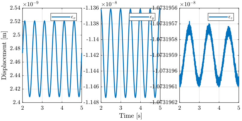
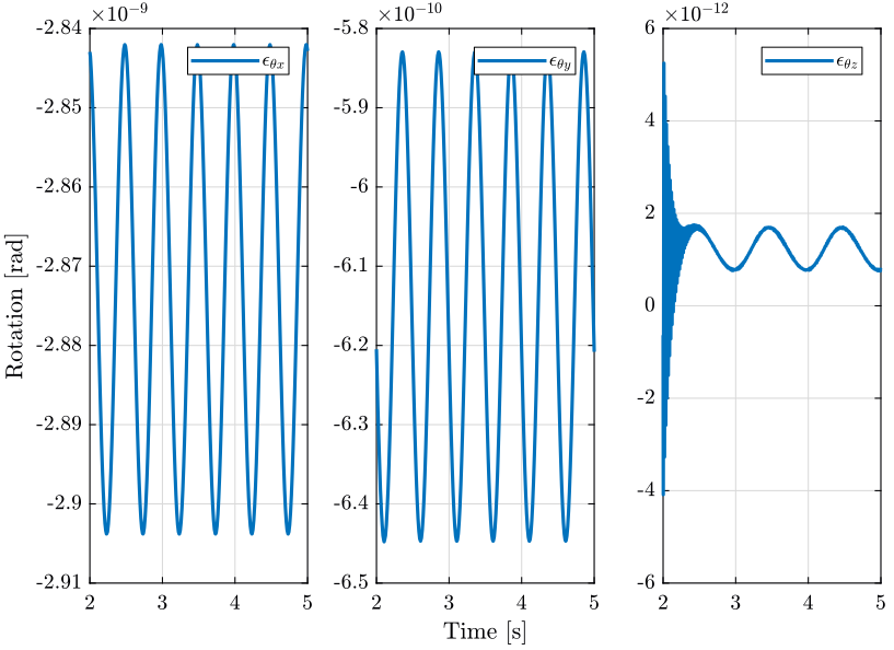
2.3 Conclusion
When everything is aligned, the resulting error motion is very small (nm range) and is quite negligible with respect to the error when disturbances are included. This residual error motion probably comes from a small misalignment somewhere.
3 Tomography Experiment with included perturbations
In this section, we also perform a tomography experiment with the sample’s center of mass aligned with the rotation axis. However this time, we include perturbations such as ground motion and stage vibrations.
3.1 Simulation Setup
We now activate the disturbances.
initializeDisturbances(...
    'Dwx', true, ... % Ground Motion - X direction
    'Dwy', true, ... % Ground Motion - Y direction
    'Dwz', true, ... % Ground Motion - Z direction
    'Fty_x', true, ... % Translation Stage - X direction
    'Fty_z', true, ... % Translation Stage - Z direction
    'Frz_z', true  ... % Spindle - Z direction
    );
We simulate the model.
sim('nass_model');
And we save the obtained data.
tomo_align_dist = struct('t', t, 'MTr', MTr);
save('./mat/experiment_tomography.mat', 'tomo_align_dist', '-append');
3.2 Analysis
load('./mat/experiment_tomography.mat', 'tomo_align_dist');
t = tomo_align_dist.t;
MTr = tomo_align_dist.MTr;
Edx = squeeze(MTr(1, 4, :));
Edy = squeeze(MTr(2, 4, :));
Edz = squeeze(MTr(3, 4, :));
% The angles obtained are u-v-w Euler angles (rotations in the moving frame)
Ery = atan2( squeeze(MTr(1, 3, :)),           squeeze(sqrt(MTr(1, 1, :).^2 + MTr(1, 2, :).^2)));
Erx = atan2(-squeeze(MTr(2, 3, :))./cos(Ery), squeeze(MTr(3, 3, :))./cos(Ery));
Erz = atan2(-squeeze(MTr(1, 2, :))./cos(Ery), squeeze(MTr(1, 1, :))./cos(Ery));
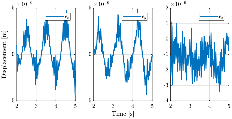
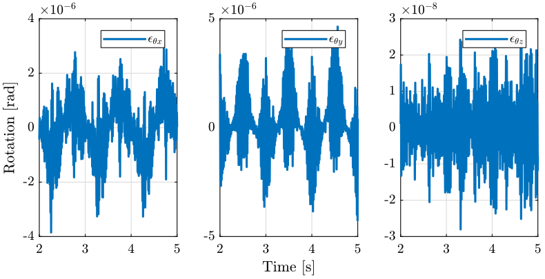
3.3 Conclusion
Error motion is what expected from the disturbance measurements.
4 Tomography when the micro-hexapod is not centered
In this section, the sample’s center of mass is not aligned with the rotation axis anymore. This is due to the fact that the micro-hexapod has performed some displacement.
No disturbances are included.
4.1 Simulation Setup
We first set the wanted translation of the Micro Hexapod.
P_micro_hexapod = [0.01; 0; 0]; % [m]
We initialize the reference path.
initializeReferences('Dh_pos', [P_micro_hexapod; 0; 0; 0], 'Rz_type', 'rotating', 'Rz_period', 1);
We initialize the stages.
initializeMicroHexapod('AP', P_micro_hexapod);
And we initialize the disturbances to zero.
initializeDisturbances(...
    'Dwx', false, ... % Ground Motion - X direction
    'Dwy', false, ... % Ground Motion - Y direction
    'Dwz', false, ... % Ground Motion - Z direction
    'Fty_x', false, ... % Translation Stage - X direction
    'Fty_z', false, ... % Translation Stage - Z direction
    'Frz_z', false  ... % Spindle - Z direction
    );
We simulate the model.
sim('nass_model');
And we save the obtained data.
tomo_not_align = struct('t', t, 'MTr', MTr);
save('./mat/experiment_tomography.mat', 'tomo_not_align', '-append');
4.2 Analysis
load('./mat/experiment_tomography.mat', 'tomo_not_align');
t = tomo_not_align.t;
MTr = tomo_not_align.MTr;
Edx = squeeze(MTr(1, 4, :));
Edy = squeeze(MTr(2, 4, :));
Edz = squeeze(MTr(3, 4, :));
% The angles obtained are u-v-w Euler angles (rotations in the moving frame)
Ery = atan2( squeeze(MTr(1, 3, :)),           squeeze(sqrt(MTr(1, 1, :).^2 + MTr(1, 2, :).^2)));
Erx = atan2(-squeeze(MTr(2, 3, :))./cos(Ery), squeeze(MTr(3, 3, :))./cos(Ery));
Erz = atan2(-squeeze(MTr(1, 2, :))./cos(Ery), squeeze(MTr(1, 1, :))./cos(Ery));
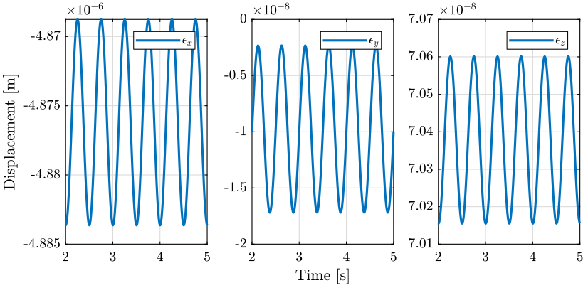
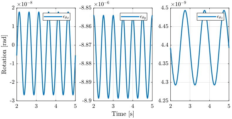
4.3 Conclusion
The main motions are translations in the X direction of the mobile platform (corresponds to the eccentricity of the micro-hexapod) and rotations along the rotating Y axis.
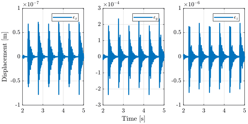
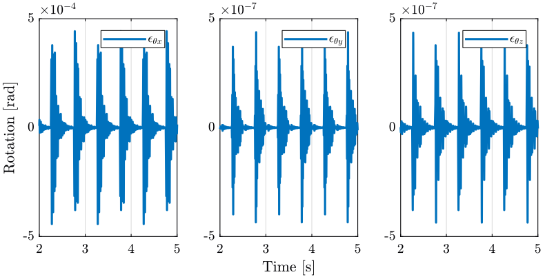
5 Raster Scans with the translation stage
5.1 Simulation Setup
We set the reference path.
initializeReferences('Dy_type', 'triangular', 'Dy_amplitude', 10e-3, 'Dy_period', 1);
We initialize the stages.
initializeGround();
initializeGranite();
initializeTy();
initializeRy();
initializeRz();
initializeMicroHexapod();
initializeAxisc();
initializeMirror();
initializeNanoHexapod('actuator', 'piezo');
initializeSample('mass', 1);
And we initialize the disturbances to zero.
initializeDisturbances(...
    'Dwx', false, ... % Ground Motion - X direction
    'Dwy', false, ... % Ground Motion - Y direction
    'Dwz', false, ... % Ground Motion - Z direction
    'Fty_x', false, ... % Translation Stage - X direction
    'Fty_z', false, ... % Translation Stage - Z direction
    'Frz_z', false  ... % Spindle - Z direction
    );
We simulate the model.
sim('nass_model');
And we save the obtained data.
ty_scan = struct('t', t, 'MTr', MTr);
save('./mat/experiment_tomography.mat', 'ty_scan', '-append');
5.2 Analysis
load('./mat/experiment_tomography.mat', 'ty_scan');
t = ty_scan.t;
MTr = ty_scan.MTr;
Edx = squeeze(MTr(1, 4, :));
Edy = squeeze(MTr(2, 4, :));
Edz = squeeze(MTr(3, 4, :));
% The angles obtained are u-v-w Euler angles (rotations in the moving frame)
Ery = atan2( squeeze(MTr(1, 3, :)),           squeeze(sqrt(MTr(1, 1, :).^2 + MTr(1, 2, :).^2)));
Erx = atan2(-squeeze(MTr(2, 3, :))./cos(Ery), squeeze(MTr(3, 3, :))./cos(Ery));
Erz = atan2(-squeeze(MTr(1, 2, :))./cos(Ery), squeeze(MTr(1, 1, :))./cos(Ery));
5.3 Conclusion
This is logic that the main error moving is translation along the Y axis and rotation along the X axis. In order to reduce the errors, we can make a smoother reference path for the translation stage.