Modal Analysis
Table of Contents
- 1. Setup
- 2. Mode extraction and importation
- 3. Positions of the sensors
- 4. Solids
- 5. From local coordinates to global coordinates
- 6. Modal Matrices
- 7. Modal Complexity
- 8. Some notes about constraining the number of degrees of freedom
- 9. TODO Normalization of mode shapes?
- 10. Compare Mode Shapes
- 11. TODO Synthesis of FRF curves
1 Setup

Figure 1: Position and orientation of the accelerometer used
2 Mode extraction and importation
First, we split the big modes.asc files into sub text files using bash.
sed '/^\s*[0-9]*[XYZ][+-]:/!d' modal_analysis_updated/modes.asc > mat/mode_shapes.txt
sed '/freq/!d' modal_analysis_updated/modes.asc | sed 's/.* = \(.*\)Hz/\1/' > mat/mode_freqs.txt
sed '/damp/!d' modal_analysis_updated/modes.asc | sed 's/.* = \(.*\)\%/\1/' > mat/mode_damps.txt
sed '/modal A/!d' modal_analysis_updated/modes.asc | sed 's/.* =\s\+\([-0-9.e]\++[0-9]\+\)\([-+0-9.e]\+\)i/\1 \2/' > mat/mode_modal_a.txt
sed '/modal B/!d' modal_analysis_updated/modes.asc | sed 's/.* =\s\+\([-0-9.e]\++[0-9]\+\)\([-+0-9.e]\+\)i/\1 \2/' > mat/mode_modal_b.txt
Then we import them on Matlab.
shapes = readtable('mat/mode_shapes.txt', 'ReadVariableNames', false); % [Sign / Real / Imag]
freqs = table2array(readtable('mat/mode_freqs.txt', 'ReadVariableNames', false)); % in [Hz]
damps = table2array(readtable('mat/mode_damps.txt', 'ReadVariableNames', false)); % in [%]
modal_a = table2array(readtable('mat/mode_modal_a.txt', 'ReadVariableNames', false)); % [Real / Imag]
modal_a = complex(modal_a(:, 1), modal_a(:, 2));
modal_b = table2array(readtable('mat/mode_modal_b.txt', 'ReadVariableNames', false)); % [Real / Imag]
modal_b = complex(modal_b(:, 1), modal_b(:, 2));
We guess the number of modes identified from the length of the imported data.
acc_n = 23; % Number of accelerometers
dir_n = 3; % Number of directions
dirs = 'XYZ';

mod_n = size(shapes,1)/acc_n/dir_n; % Number of modes
As the mode shapes are split into 3 parts (direction plus sign, real part and imaginary part), we aggregate them into one array of complex numbers.
T_sign = table2array(shapes(:, 1));
T_real = table2array(shapes(:, 2));
T_imag = table2array(shapes(:, 3));

modes = zeros(mod_n, acc_n, dir_n);

for mod_i = 1:mod_n
  for acc_i = 1:acc_n
    % Get the correct section of the signs
    T = T_sign(acc_n*dir_n*(mod_i-1)+1:acc_n*dir_n*mod_i);
    for dir_i = 1:dir_n
      % Get the line corresponding to the sensor
      i = find(contains(T, sprintf('%i%s',acc_i, dirs(dir_i))), 1, 'first')+acc_n*dir_n*(mod_i-1);
      modes(mod_i, acc_i, dir_i) = str2num([T_sign{i}(end-1), '1'])*complex(T_real(i),T_imag(i));
    end
  end
end
The obtained mode frequencies and damping are shown below.
data2orgtable([freqs, damps], {}, {'Frequency [Hz]', 'Damping [%]'}, ' %.1f ');
| Frequency [Hz] | Damping [%] |
|---|---|
| 11.4 | 8.7 |
| 18.5 | 11.8 |
| 37.6 | 6.4 |
| 39.4 | 3.6 |
| 54.0 | 0.2 |
| 56.1 | 2.8 |
| 69.7 | 4.6 |
| 71.6 | 0.6 |
| 72.4 | 1.6 |
| 84.9 | 3.6 |
| 90.6 | 0.3 |
| 91.0 | 2.9 |
| 95.8 | 3.3 |
| 105.4 | 3.3 |
| 106.8 | 1.9 |
| 112.6 | 3.0 |
| 116.8 | 2.7 |
| 124.1 | 0.6 |
| 145.4 | 1.6 |
| 150.1 | 2.2 |
| 164.7 | 1.4 |
3 Positions of the sensors
We process the file exported from the modal software containing the positions of the sensors using bash.
cat modal_analysis_updated/id31_nanostation_modified.cfg | grep NODES -A 23 | sed '/\s\+[0-9]\+/!d' | sed 's/\(.*\)\s\+0\s\+.\+/\1/' > mat/acc_pos.txt
We then import that on matlab, and sort them.
acc_pos = readtable('mat/acc_pos.txt', 'ReadVariableNames', false);
acc_pos = table2array(acc_pos(:, 1:4));
[~, i] = sort(acc_pos(:, 1));
acc_pos = acc_pos(i, 2:4);
The positions of the sensors relative to the point of interest are shown below.
data2orgtable(1000*acc_pos, {}, {'x [mm]', 'y [mm]', 'z [mm]'}, ' %.0f ');
| x [mm] | y [mm] | z [mm] |
|---|---|---|
| -64 | -64 | -296 |
| -64 | 64 | -296 |
| 64 | 64 | -296 |
| 64 | -64 | -296 |
| -385 | -300 | -417 |
| -420 | 280 | -417 |
| 420 | 280 | -417 |
| 380 | -300 | -417 |
| -475 | -414 | -427 |
| -465 | 407 | -427 |
| 475 | 424 | -427 |
| 475 | -419 | -427 |
| -320 | -446 | -786 |
| -480 | 534 | -786 |
| 450 | 534 | -786 |
| 295 | -481 | -786 |
| -730 | -526 | -951 |
| -735 | 814 | -951 |
| 875 | 799 | -951 |
| 865 | -506 | -951 |
| -155 | -90 | -594 |
| 0 | 180 | -594 |
| 155 | -90 | -594 |
4 Solids
We consider the following solid bodies:
- Bottom Granite
- Top Granite
- Translation Stage
- Tilt Stage
- Spindle
- Hexapod
We create a structure solids that contains the accelerometer number of each solid bodies (as shown on figure 1).
solids = {};
solids.granite_bot = [17, 18, 19, 20];
solids.granite_top = [13, 14, 15, 16];
solids.ty          = [9, 10, 11, 12];
solids.ry          = [5, 6, 7, 8];
solids.rz          = [21, 22, 23];
solids.hexa        = [1, 2, 3, 4];

solid_names = fields(solids);
5 From local coordinates to global coordinates

From the figure above, we can write:
\begin{align*} \vec{v}_1 &= \vec{v} + \Omega \vec{p}_1\\ \vec{v}_2 &= \vec{v} + \Omega \vec{p}_2\\ \vec{v}_3 &= \vec{v} + \Omega \vec{p}_3\\ \vec{v}_4 &= \vec{v} + \Omega \vec{p}_4 \end{align*}With
\begin{equation} \Omega = \begin{bmatrix} 0 & -\Omega_z & \Omega_y \\ \Omega_z & 0 & -\Omega_x \\ -\Omega_y & \Omega_x & 0 \end{bmatrix} \end{equation}\(\vec{v}\) and \(\Omega\) represent to velocity and rotation of the solid expressed in the frame \(\{O\}\).
We can rearrange the equations in a matrix form:
\begin{equation} \left[\begin{array}{ccc|ccc} 1 & 0 & 0 & 0 & p_{1z} & -p_{1y} \\ 0 & 1 & 0 & -p_{1z} & 0 & p_{1x} \\ 0 & 0 & 1 & p_{1y} & -p_{1x} & 0 \\ \hline & \vdots & & & \vdots & \\ \hline 1 & 0 & 0 & 0 & p_{4z} & -p_{4y} \\ 0 & 1 & 0 & -p_{4z} & 0 & p_{4x} \\ 0 & 0 & 1 & p_{4y} & -p_{4x} & 0 \end{array}\right] \begin{bmatrix} v_x \\ v_y \\ v_z \\ \hline \Omega_x \\ \Omega_y \\ \Omega_z \end{bmatrix} = \begin{bmatrix} v_{1x} \\ v_{1y} \\ v_{1z} \\\hline \vdots \\\hline v_{4x} \\ v_{4y} \\ v_{4z} \end{bmatrix} \end{equation}and then we obtain the velocity and rotation of the solid in the wanted frame \(\{O\}\):
\begin{equation} \begin{bmatrix} v_x \\ v_y \\ v_z \\ \hline \Omega_x \\ \Omega_y \\ \Omega_z \end{bmatrix} = \left[\begin{array}{ccc|ccc} 1 & 0 & 0 & 0 & p_{1z} & -p_{1y} \\ 0 & 1 & 0 & -p_{1z} & 0 & p_{1x} \\ 0 & 0 & 1 & p_{1y} & -p_{1x} & 0 \\ \hline & \vdots & & & \vdots & \\ \hline 1 & 0 & 0 & 0 & p_{4z} & -p_{4y} \\ 0 & 1 & 0 & -p_{4z} & 0 & p_{4x} \\ 0 & 0 & 1 & p_{4y} & -p_{4x} & 0 \end{array}\right]^{-1} \begin{bmatrix} v_{1x} \\ v_{1y} \\ v_{1z} \\\hline \vdots \\\hline v_{4x} \\ v_{4y} \\ v_{4z} \end{bmatrix} \end{equation}This inversion is equivalent to a mean square problem.
mode_shapes_O = zeros(mod_n, length(solid_names), 6);

for mod_i = 1:mod_n
  for solid_i = 1:length(solid_names)
    solids_i = solids.(solid_names{solid_i});

    Y = reshape(squeeze(modes(mod_i, solids_i, :))', [], 1);

    A = zeros(3*length(solids_i), 6);
    for i = 1:length(solids_i)
      A(3*(i-1)+1:3*i, 1:3) = eye(3);

      A(3*(i-1)+1:3*i, 4:6) = [0 acc_pos(i, 3) -acc_pos(i, 2) ; -acc_pos(i, 3) 0 acc_pos(i, 1) ; acc_pos(i, 2) -acc_pos(i, 1) 0];
    end

    mode_shapes_O(mod_i, solid_i, :) = A\Y;
  end
end
6 Modal Matrices
We want to obtain the two following matrices: \[ \Omega = \begin{bmatrix} \omega_1^2 & & 0 \\ & \ddots & \\ 0 & & \omega_n^2 \end{bmatrix}; \quad \Psi = \begin{bmatrix} & & \\ \{\psi_1\} & \dots & \{\psi_n\} \\ & & \end{bmatrix} \]
[ ]How to add damping to the eigen value matrix?
eigen_value_M = diag(freqs*2*pi);
eigen_vector_M = reshape(mode_shapes_O, [mod_n, 6*length(solid_names)])';
\[ \{\psi_1\} = \begin{Bmatrix} \psi_{1_x} & \psi_{2_x} & \dots & \psi_{6_x} & \psi_{1_x} & \dots & \psi_{1\Omega_x} & \dots & \psi_{6\Omega_z} \end{Bmatrix}^T \]
7 Modal Complexity
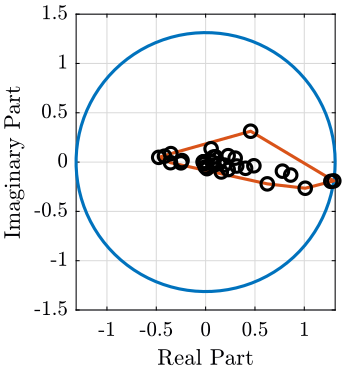
Complexity of one mode
mod_i = 1;
i_max = convhull(real(eigen_vector_M(:, mod_i)), imag(eigen_vector_M(:, mod_i)));
radius = max(abs(eigen_vector_M(:, mod_i)));
theta = linspace(0, 2*pi, 100);

figure;
hold on;
plot(radius*cos(theta), radius*sin(theta), '-');
plot(real(eigen_vector_M(i_max, mod_i)), imag(eigen_vector_M(i_max, mod_i)), '-');
plot(real(eigen_vector_M(:, mod_i)), imag(eigen_vector_M(:, mod_i)), 'ko');
hold off;
xlabel('Real Part'); ylabel('Imaginary Part');
axis manual equal

Figure 3: Modal Complexity of one mode
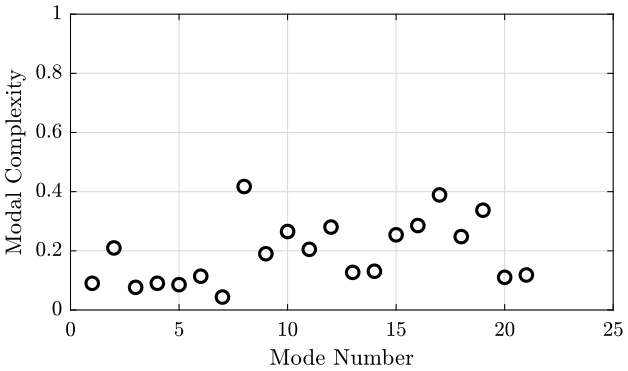
Complexity function of the mode order.
modes_complexity = zeros(mod_n, 1);
for mod_i = 1:mod_n
  i = convhull(real(eigen_vector_M(:, mod_i)), imag(eigen_vector_M(:, mod_i)));
  area_complex = polyarea(real(eigen_vector_M(i, mod_i)), imag(eigen_vector_M(i, mod_i)));
  area_circle = pi*max(abs(eigen_vector_M(:, mod_i)))^2;
  modes_complexity(mod_i) = area_complex/area_circle;
end

figure;
plot(1:mod_n, modes_complexity, 'ok');
ylim([0, 1]);
xlabel('Mode Number'); ylabel('Modal Complexity');

Figure 4: Modal complexity for each mode
8 Some notes about constraining the number of degrees of freedom
We want to have the two eigen matrices.
They should have the same size \(n \times n\) where \(n\) is the number of modes as well as the number of degrees of freedom. Thus, if we consider 21 modes, we should restrict our system to have only 21 DOFs.
Actually, we are measured 6 DOFs of 6 solids, thus we have 36 DOFs.
From the mode shapes animations, it seems that in the frequency range of interest, the two marbles can be considered as one solid. We thus have 5 solids and 30 DOFs.
In order to determine which DOF can be neglected, two solutions seems possible:
- compare the mode shapes
- compare the FRFs
The question is: in which base (frame) should be express the modes shapes and FRFs? Is it meaningful to compare mode shapes as they give no information about the amplitudes of vibration?
| Stage | Motion DOFs | Parasitic DOF | Total DOF | Description of DOF |
|---|---|---|---|---|
| Granite | 0 | 3 | 3 | |
| Ty | 1 | 2 | 3 | Ty, Rz |
| Ry | 1 | 2 | 3 | Ry, |
| Rz | 1 | 2 | 3 | Rz, Rx, Ry |
| Hexapod | 6 | 0 | 6 | Txyz, Rxyz |
| 9 | 9 | 18 |
9 TODO Normalization of mode shapes?
We normalize each column of the eigen vector matrix. Then, each eigenvector as a norm of 1.
eigen_vector_M = eigen_vector_M./vecnorm(eigen_vector_M);
10 Compare Mode Shapes
Let's say we want to see for the first mode which DOFs can be neglected. In order to do so, we should estimate the motion of each stage in particular directions. If we look at the z motion for instance, we will find that we cannot neglect that motion (because of the tilt causing z motion).
mode_i = 3;
dof_i = 6;

mode = eigen_vector_M(dof_i:6:end, mode_i);

figure;
hold on;
for i=1:length(mode)
  plot([0, real(mode(i))], [0, imag(mode(i))], '-', 'DisplayName', solid_names{i});
end
hold off;
legend();
figure;
subplot(2, 1, 1);
hold on;
for i=1:length(mode)
  plot(1, norm(mode(i)), 'o');
end
hold off;
ylabel('Amplitude');

subplot(2, 1, 2);
hold on;
for i=1:length(mode)
  plot(1, 180/pi*angle(mode(i)), 'o', 'DisplayName', solid_names{i});
end
hold off;
ylim([-180, 180]); yticks([-180:90:180]);
ylabel('Phase [deg]');
legend();
test = mode_shapes_O(10, 1, :)/norm(squeeze(mode_shapes_O(10, 1, :)));
test = mode_shapes_O(10, 2, :)/norm(squeeze(mode_shapes_O(10, 2, :)));