Effect of the rotation of the Slip-Ring
Table of Contents
1 Measurement Description
Random Signal is generated by one DAC of the SpeedGoat.
The signal going out of the DAC is split into two:
- one BNC cable is directly connected to one ADC of the SpeedGoat
- one BNC cable goes two times in the Slip-Ring (from bottom to top and then from top to bottom) and then is connected to one ADC of the SpeedGoat
Two measurements are done.
| Data File | Description |
|---|---|
mat/data_001.mat |
Slip-ring not turning |
mat/data_002.mat |
Slip-ring turning |
For each measurement, the measured signals are:
| Data File | Description |
|---|---|
t |
Time vector |
x1 |
Direct signal |
x2 |
Signal going through the Slip-Ring |
The goal is to determine is the signal is altered when the spindle is rotating.
Here, the rotation speed of the Slip-Ring is set to 1rpm.
2 Load data
We load the data of the z axis of two geophones.
sr_off = load('mat/data_001.mat', 't', 'x1', 'x2');
sr_on  = load('mat/data_002.mat', 't', 'x1', 'x2');
3 Analysis
Let's first look at the signal produced by the DAC (figure 1).
figure;
hold on;
plot(sr_on.t,  sr_on.x1);
hold off;
xlabel('Time [s]'); ylabel('Voltage [V]');
xlim([0 10]);
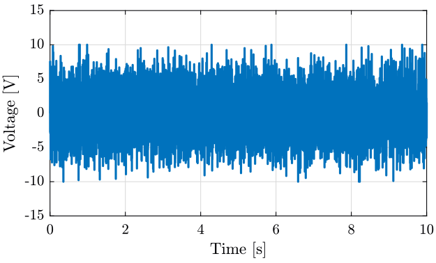
Figure 1: Random signal produced by the DAC
We now look at the difference between the signal directly measured by the ADC and the signal that goes through the slip-ring (figure 2).
figure;
hold on;
plot(sr_on.t,  sr_on.x1 - sr_on.x2,  'DisplayName', 'Slip-Ring - $\omega = 1rpm$');
plot(sr_off.t, sr_off.x1 - sr_off.x2,'DisplayName', 'Slip-Ring off');
hold off;
xlabel('Time [s]'); ylabel('Voltage [V]');
xlim([0 10]);
legend('Location', 'northeast');
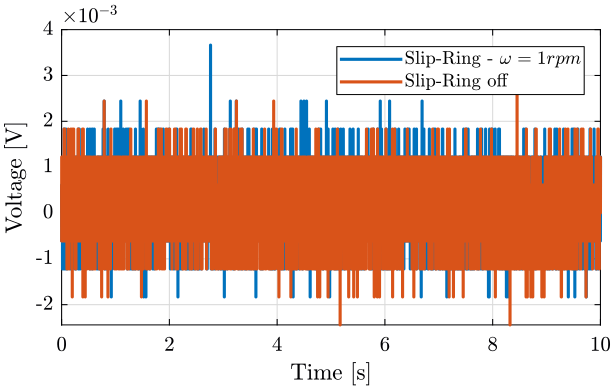
Figure 2: Alteration of the signal when the slip-ring is turning
4 Conclusion
Remaining questions:
- Should the measurement be redone using voltage amplifiers?
- Use higher rotation speed and measure for longer periods (to have multiple revolutions) ?