Modal Analysis - Derivation of Mathematical Models
Table of Contents
1 Type of Model
The model that we want to obtain is a multi-body model. It is composed of several solid bodies connected with springs and dampers. The solid bodies are represented with different colors on figure 1.
In the simscape model, the solid bodies are:
- the granite (1 or 2 solids)
- the translation stage
- the tilt stage
- the spindle and slip-ring
- the hexapod
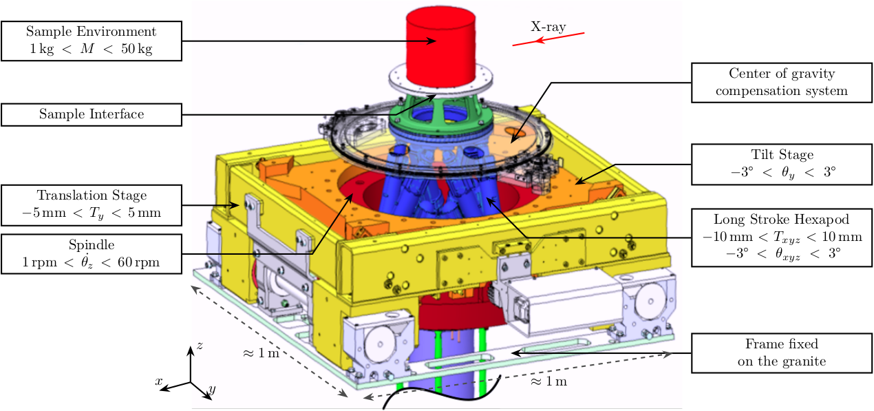
Figure 1: CAD view of the ID31 Micro-Station
However, each of the DOF of the system may not be relevant for the modes present in the frequency band of interest. For instance, the translation stage may not vibrate in the Z direction for all the modes identified. Then, we can block this DOF and this simplifies the model.
The modal identification done here will thus permit us to determine which DOF can be neglected.
2 Extract Physical Matrices
Let’s recall that: \[ \Lambda = \begin{bmatrix} s_1 & & 0 \\ & \ddots & \\ 0 & & s_N \end{bmatrix}_{N \times N}; \quad \Psi = \begin{bmatrix} & & \\ \{\psi_1\} & \dots & \{\psi_N\} \\ & & \end{bmatrix}_{M \times N} ; \quad A = \begin{bmatrix} a_1 & & 0 \\ & \ddots & \\ 0 & & a_N \end{bmatrix}_{N \times N}; \]
\begin{align} M &= \frac{1}{2} \left[ \text{Re}(\Psi A^{-1} \Lambda \Psi^T ) \right]^{-1} \\ C &= -2 M \text{Re}(\Psi A^{-1} \Lambda^2 A^{-1} \Psi^T ) M \\ K &= -\frac{1}{2} \left[ \text{Re}(\Psi \Lambda^{-1} A^{-1} \Psi^T) \right]^{-1} \end{align}psi = eigen_vec_CoM; a = modal_a_M; lambda = eigen_val_M; M = 0.5*inv(real(psi*inv(a)*lambda*psi')); C = -2*M*real(psi*inv(a)*lambda^2*inv(a)*psi')*M; K = -0.5*inv(real(psi*inv(lambda)*inv(a)*psi'));
From (Ewins 2000)
\begin{align} [M] &= [\Phi]^{-T} [I] [\Phi]^{-1} \\ [K] &= [\Phi]^{-T} [\lambda_r^2] [\Phi]^{-1} \end{align}3 Some notes about constraining the number of degrees of freedom
We want to have the two eigen matrices.
They should have the same size \(n \times n\) where \(n\) is the number of modes as well as the number of degrees of freedom. Thus, if we consider 21 modes, we should restrict our system to have only 21 DOFs.
Actually, we are measured 6 DOFs of 6 solids, thus we have 36 DOFs.
From the mode shapes animations, it seems that in the frequency range of interest, the two marbles can be considered as one solid. We thus have 5 solids and 30 DOFs.
In order to determine which DOF can be neglected, two solutions seems possible:
- compare the mode shapes
- compare the FRFs
The question is: in which base (frame) should be express the modes shapes and FRFs? Is it meaningful to compare mode shapes as they give no information about the amplitudes of vibration?
| Stage | Motion DOFs | Parasitic DOF | Total DOF | Description of DOF |
|---|---|---|---|---|
| Granite | 0 | 3 | 3 | |
| Ty | 1 | 2 | 3 | Ty, Rz |
| Ry | 1 | 2 | 3 | Ry, |
| Rz | 1 | 2 | 3 | Rz, Rx, Ry |
| Hexapod | 6 | 0 | 6 | Txyz, Rxyz |
| 9 | 9 | 18 |